Fabrication of high temperature grating on thermal barrier coatings based on solute-solvent separation soft lithography
2018-04-10 08:14:23BozhaoFanHuiminXie
Bozhao Fan, Huimin Xie*
AML, School of Aerospace Engineering, Tsinghua University, Beijing 100084, China
Thermal barrier coatings (TBCs), which are extensively applied for protecting the underneath metallic parts of gas turbine from high temperature oxidation, play an essential role in the field of aircraft industry. Meanwhile, the mechanical behavior of TBCs, which significantly influences the performance of high temperature component, has been drawing an increasing attention in recent years [1-3]. Beghini et al. [4, 5] utilized a four-point bending rig to measure the elastic properties of ceramic coating and bonding coating in TBCs at the temperature ranging from 20°C to 900°C with strain gauges and a linear variable differential transformer transducer. Liu et al. [6] employed an interfacial indentation technique to investigate the interfacial toughness of TBCs at different oxidation time and temperatures. Qu et al. [7]designed an elevated-temperature depth-sensing instrumented indentation apparatus to analyze the thermo-mechanical response of TBCs by measuring the load-depth curves at the temperature from 600°C to 1500°C.
Nevertheless, a series of more complex thermo-mechanical problems such as crack initiation and fracture failure in TBCs will occur, when TBCs have been in service for a long time. In order to understand its mechanical behavior and analyze the relat-ive mechanism of failure, full-field deformation measurement techniques based on high frequency grating were developed.Jiang et al. [8] utilized 1200 lines/mm grating to measure the distribution of residual stresses of the Ni–Cr–B–Si coatings alongside the specimen thickness direction. Zhu et al. [9] analyzed the cross-sectional residual stress in TBCs with moiré interferometry and nanoindentation technique. Tang et al. [10] investigated the interfacial failure process and mechanical properties of TBCs by measuring macro-scale and micro-scale deformation fields of the specimens subjected to three-point bending load.Wu et al. [11] applied modified element birth-death technology and moiré interferometry combined with hole-drilling method to analyze the evolution of residual stress in TBCs during air plasma spraying (APS) process.
However, in the practical application of TBCs, the environment temperature is usually above 800°C. The available grating fabrication techniques [8-11] cannot be utilized to fabricate high temperature grating on TBCs. Consequently, it is crucial to develop a novel grating fabrication technique to satisfy the requirement for accurately measuring high temperature deformation.
Compared to common substrate materials such as metal,glass, silicon wafer and polymethyl methacrylate (PMMA) plate in the process of fabricating grating, the structure of TBCs produced by APS process is more complex, which is exhibited in Fig. 1.TBCs consist of a ceramic coating, a bonding coating and substrate. The substrate material is GH4169 Nickel-based alloy and the size is 50×10×6 mm (thickness of 6 mm). During the specimen preparation process, substrate is exposed to a grit-blasting treatment to roughen the surface for a better adhesion property.And then 0.08 mm bonding coating and 1 mm ZrO2-8 wt%Y2O3(YSZ) ceramic coating are deposited successively on the top of substrate in an air atmosphere with plasma spraying technology.
After the thermal spraying process, the surface of ceramic coating in TBCs is coarse and the microscopic morphology is showed in Fig. 2(a). The size is about 397.46 × 302.38 μm. Meanwhile, a digital microscope (VHX-500F produced by KEYENCE)is employed to reconstruct three-dimensional morphology of ceramic coating, and the result is exhibited in Fig. 2(b). The field of view is about 610 × 457 μm at 2000× magnification. The maximum height is 41.6 μm, and a defect exists around the center.The reconstructed result further reveals that the surface of ceramic coating is uneven and it needs to be polished before grating fabrication process.
In the experiment, a two-step operation is adopted to polish the top surface of TBCs. In the first step, diamond powder as abrasive is utilized to polish the surface of ceramic coating on a thick iron plate. And then, in the second step, the ceramic surface is further polished with fine SiO2powder to attain the mirror plane. Its roughness should be less than 0.04 μm and flatness is less than 9 μm. The surface morphology of ceramic coating after polishing is showed in Fig. 3(a), which is flatter and smoother when being compared to the original surface in Fig.2(a). However, some inclusions are found on the ceramic surface in Fig. 3(a), which are usually at the locations of hole or defect before polishing. In order to investigate the source of these inclusions, the chemistry compositions of ceramic and inclusion material are analyzed with 10 keV energy dispersive X-ray spectroscope (EDS). The experiment results in Fig. 3(b) illustrate that inclusion material consist of oxygen and silicon, and the atom ratio is about 2:1. This result reveals that the inclusions are made of SiO2and they may inlays ceramic surface in the second step during polishing. Since these inclusions may have an influence on the contact stability, additional treatment is needed to improve the surface performance of the polished ceramic coating.
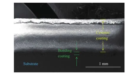
Fig. 1. Crossing-sectional structure of TBCs in scanning electron microscope (SEM).
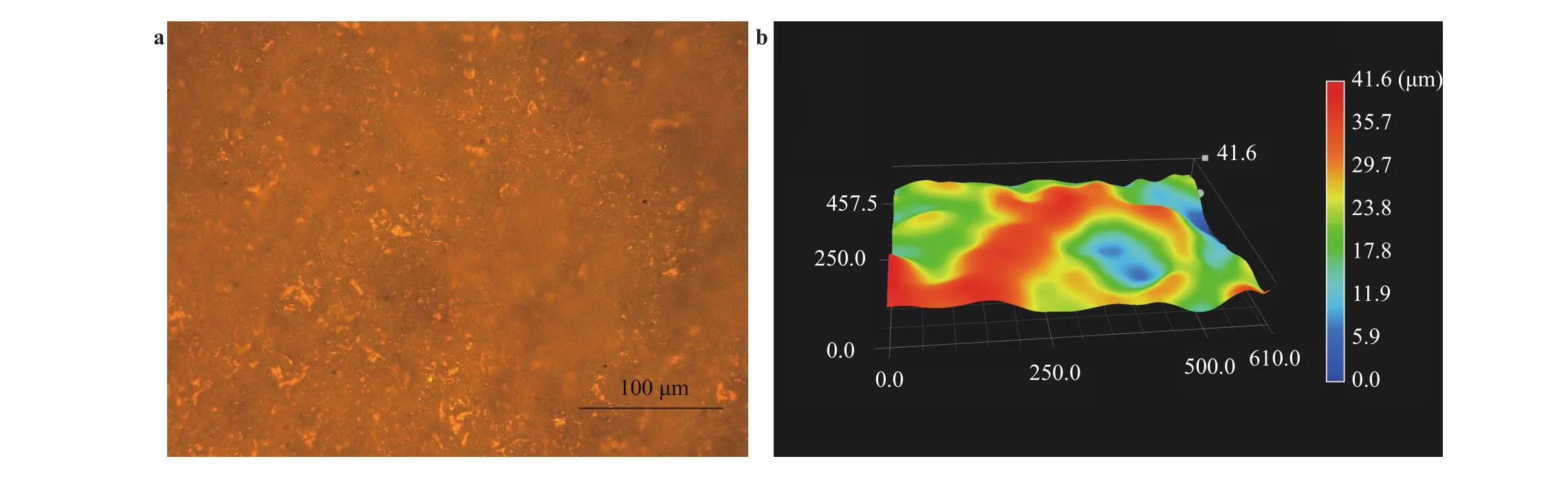
Fig. 2. (a) Surface morphology of ceramic coating in digital microscope, (b) reconstructed three-dimensional morphology of ceramic coating(unit: μm).
In this study, an etched-SiO-film grating fabrication technique, which is suitable for porous material, is developed based on solute-solvent separation soft lithography at our laboratory in Ref. [12]. The detailed fabrication process is illustrated in Fig. 4 and the experimental parameters are listed in Table. 1.
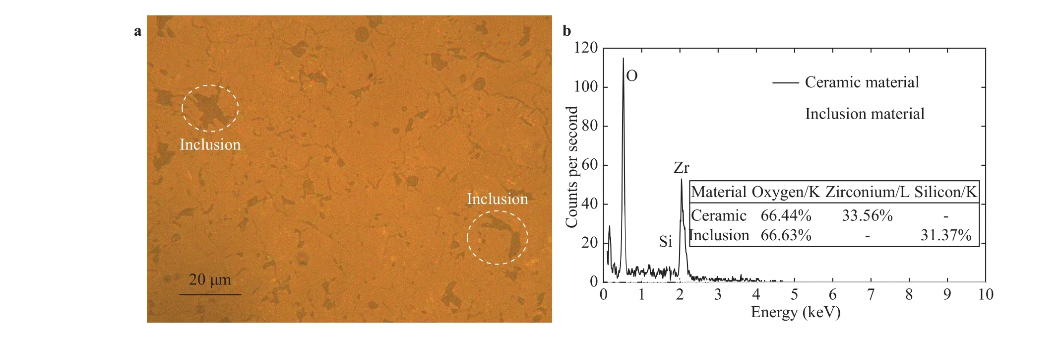
Fig. 3. (a) Surface morphology of ceramic coating after polishing, (b) chemistry compositions of ceramic coating analyzed with EDS in SEM (K and L represent the order of electron shell).
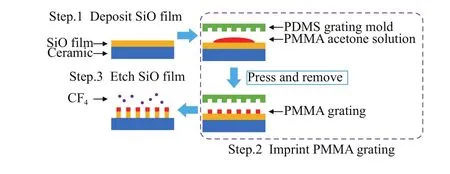
Fig. 4. Fabrication process of high temperature grating.
During the grating fabrication process, a thin SiO film is deposited on the polished surface of ceramic coating using physical vapor deposition (PVD) technology. The inclusions can be filled up to prevent the PMMA acetone solution from leaking and to improve the contact performance of ceramic coating.Then, PMMA acetone solution is dropped onto the SiO film surface and a polydimethylsiloxane (PDMS) soft mold with a 600 lines/mm crossing-type grating pattern is employed for imprinting. After solidification, the soft mold is removed and a residuallayer-free 600 lines/mm PMMA grating is fabricated on the ceramic surface. Finally, reactive ion etching (RIE) technology is employed to replicate the microstructure of grating to the SiO film with the PMMA grating as the mask.
The TBCs at different grating fabrication steps are exhibited in Fig. 5. Before polishing, the surface of ceramic coating is rough, while the surface becomes flatter and smoother with a better reflectivity after polishing. This reveals that the two-step polishing operation can significantly improve the surface property of ceramic coating. Then, the surface of TBCs reflects the green light due to the emission spectrum of SiO material after PVD process. Finally, a large-scale grating is successfully fabricated on the ceramic coating, and surface reflects pink light due to the existing PMMA film on the top surface.
After the SiO film is etched, the TBCs with grating need be heated to remove the residual PMMA material on the ceramicsurface. Besides, heat treatment process can also further improve the high temperature resistance of TBCs. In this process,SiO material is oxidized to SiO2, which has a better thermal endurance. Therefore, the TBCs with grating is heated at the temperature ranging from 25°C to 300°C with the increasing time of 60 min. Then, the ambient temperature is maintained at 300°C for 30 min. The curve of this heat treatment process is illustrated in Fig. 6. Besides, after heat treatment, the distinct microstructure of grating is observed by digital microscope in Fig. 6.
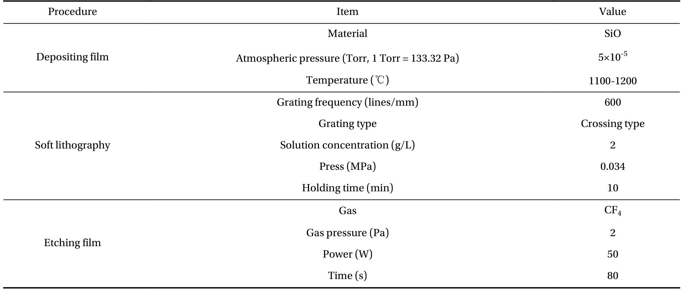
Table 1 Experimental parameters of high temperature grating fabrication process.
In order to examine the operational performance of this fabricated grating, the TBCs with grating are further heated at higher temperatures and the experiment results are exhibited in Fig.6. The maximum temperature at each experiment is 600°C,800°C, and 1000°C, while the corresponding increasing time is 90 min, 120 min, and 150 min, respectively. The increasing rate of temperature in all the experiments is about 6.5°C/min, which can avoid the effect of thermal shock on TBCs. Afterwards, 30 min holding time is taken to examine the resistibility of grating to oxidation at different temperatures. Meanwhile, the planar structure of grating after heated is observed in digital microscope, and the respective results are shown in Fig. 6. The experimental results show that the grating structure is stable at different temperatures and it has a good resistance to oxidation at high temperature up to 1000°C.
In the practical application, an indentation apparatus with a Vickers hardness indenter is utilized to induce a small indentation mark on the TBCs after heated at 800°C and surface morphology is detected by SEM in Fig. 7(a). A series of small cracks appear around the edge of indentation. The results reveal that SiO grating has a good adhesive strength with the ceramic coating even if the local ceramic coating is destroyed by the indenter.Besides, the planar structure of grating around the indentation are observed by SEM in Fig. 7(b). In this study, geometry phase analysis (GPA) is employed to investigate the displacement and strain field in the region of interest (ROI). The basic principle of GPA is introduced in the following sections [13-15].
A grating image can be regarded as a series of fringes and the intensity can be expressed in:

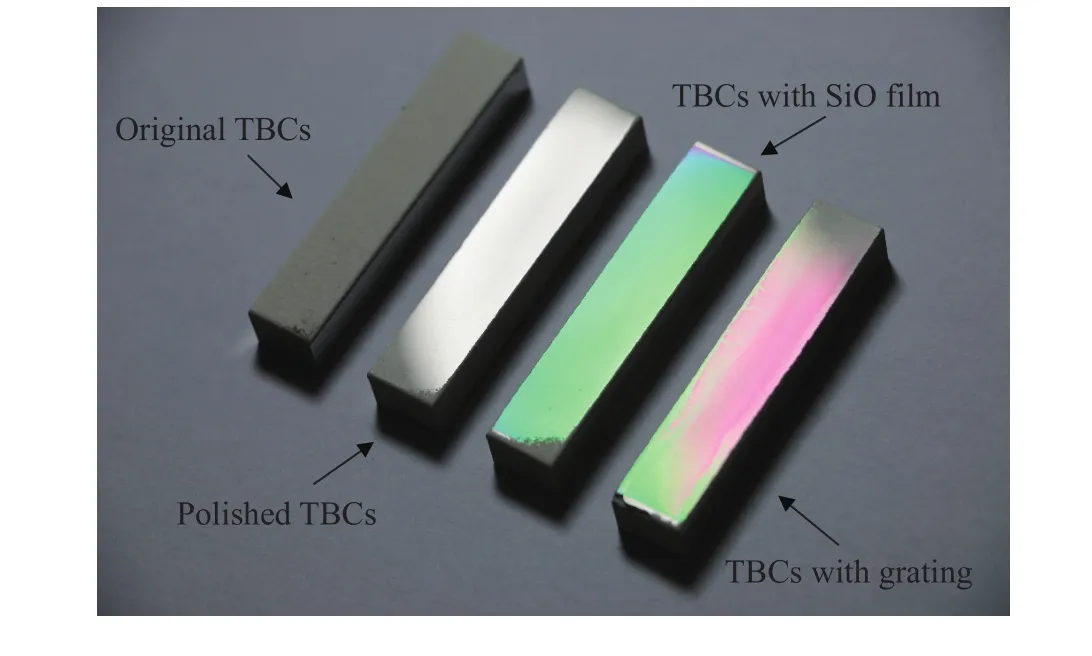
Fig. 5. TBCs at different fabrication steps.
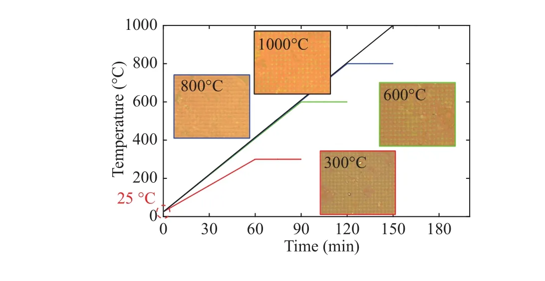
Fig. 6. Curves of experimental temperature and planar grating structure after heated at different temperatures (300°C, 600°C, 800°C,1000°C).
wheregrepresents the grating vectors andris the corresponding coordinate. After Fourier transforming and filtering intensity image of grating, the Fourier components can be determined by:

whereAg(r) describes the local contrast of fringes and phases.Meanwhile, the phasePg(r), which is related to the displacement fieldu(r), can be given by:

Compared with two phase image,Pg1(r) before the deformation andPg2(r) after the deformation, the displacement field can be further calculated with:

Here,a1anda2are the basis vectors for the grating in real space corresponding to the grating frequencyg1andg2. Therefore, the strain field based on Eq. (4) can be obtained with:

Based on Eq. (1)-(5), the displacement and normal strain field in ROI are obtained in Fig. 7(c) and (d). During the calculation process, the reference image is created in the digital form with the same frequency as the grating image before indentation. The displacement field illustrates that two intense discontinuity appear in the center position where two cracks exist. In addition, the scale in Fig. 7(c) is that one pixels represents about 0.05 μm displacement. Therefore, the maximum crack opening displacement in Fig. 7(c) is about 1 μm, which is in accord with the observation result in Fig. 7(b). Furthermore, the normal strain field in Fig. 7(d) reveals that the intense strain concentration is located at the crack and the shape of strain concentration region is similar to the shape of crack. In general, these experiment results confirm that the SiO grating is capable of accurately responding the displacement and strain field around the crack on TBCs.
In conclusion, an etched-SiO-film grating fabrication technique is developed to fabricate a 600 lines/mm high temperature SiO grating on the porous surface of ceramic coating in TBCs based on solute-solvent separation soft lithography. The experiment results verify the grating fabrication technique has a good oxidation resistibility against 1000°C. In addition, the SiO grating has a good adhesion strength with the porous ceramic coat-ing and is suitable to be used for inhomogeneous deformation measurement, especially for crack failure. In brief, the etched-SiO-film grating fabrication technique in this paper has an enormous potential for determining the high temperature mechanical behavior of TBCs or other porous materials and structures.
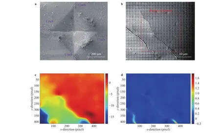
Fig. 7. (a) Surface morphology of ceramic coating after indentation in SEM, (b) surface crack around indentation, (c) displacement field in ROI,(d) normal strain field in ROI.
Acknowledges
This research was financially supported by the National Natural Science Foundation of China (11672153, 11232008).
[1]C. Li, X. Zhang, Y. Chen, et al., Understanding the residual stress distribution through the thickness of atmosphere plasma sprayed (APS) thermal barrier coatings (TBCs) by high energy synchrotron XRD; digital image correlation (DIC) and image based modelling, Acta Materialia 132 (2017) 1–12.
[2]C. Bumgardner, B. Croom, X.D. Li, High-temperature delamination mechanisms of thermal barrier coatings: In-situ digital image correlation and finite element analyses, Acta Materialia 128 (2017) 54–63.
[3]L. Yang, J. Yang, J. Xia, et al., Characterization of the strain in the thermal barrier coatings caused by molten CaO-MgOAl2O3-SiO2using a digital image correlation technique, Surface& Coatings Technology 322 (2017) 1–9.
[4]M. Beghini, L. Bertini, F. Frendo, Measurement of coatings'elastic properties by mechanical methods: Part 1. Consideration on experimental errors, Experimental Mechanics 41 (2001)293–304.
[5]M. Beghini, G. Benamati, L. Bertini, Measurement of coatings'elastic properties by mechanical methods: Part 2. Application to thermal barrier coatings, Experimental Mechanics 41 (2001)305–311.
[6]Y.K. Liu, Y.H. Liu, P. Lours, et al., Influence of isothermal aging conditions on APS TBC's interfacial fracture toughness, Surface& Coatings Technology 313 (2017) 417–424.
[7]Z.L. Qu, M.A. Yu, Y.C. Liu, et al., An elevated-temperature depth-sensing instrumented indentation apparatus for investigating thermo-mechanical behaviour of thermal barrier coatings, Review of Scientific Instruments 88 (2017) 045102.
[8]Y. Jiang, B.S. Xu, H.D. Wang, et al., Determination of residual stresses within plasma spray coating using Moiré interferometry method, Applied Surface Science 257 (2011) 2332–2336.
[9]J.G. Zhu, H.M. Xie, Z.X. Hu, et al., Cross-sectional residual stresses in thermal spray coatings measured by Moiré interferometry and nanoindentation technique, Journal of Thermal Spray Technology 21 (2012) 810–817.
[10]M.J. Tang, H.M. Xie, J.G. Zhu, The failure mechanisms of TBC structure by moiré interferometry, Materials Science and Engineering: A 565 (2013) 142–147.
[11]L.F. Wu, J.G. Zhu, H.M. Xie, Numerical and experimental investigation of residual stress in thermal barrier coatings during APS process, Journal of Thermal Spray Technology 23 (2014)653–665.
[12]X.L. Dai, H.M. Xie, A simple and residual-layer-free solutesolvent separation soft lithography method, Journal of Micromechanics and Microengineering 25 (2015) 095013.
[13]M.J. H?ch, J.L. Putaux, J.M. Pénisson, Measurement of the displacement field of dislocations to 0.03 ? by electron microscopy, Nature 423 (2003) 270–274.
[14]M.J. H?ch, E. Snoeck, R. Kilaas, et al., Quantitative measurement of displacement and strain fields from HREM micrographs, Ultramicroscopy 74 (1998) 131–146.
[15]J.J. Li, C.W. Zhao, Y.M. Xing, et al., In-situ SEM investigation of sub-microscale deformation fields around a crack-tip in silicon,Optics and Lasers in Engineering 50 (2012) 1694–1698.
 Theoretical & Applied Mechanics Letters2018年1期
- Theoretical & Applied Mechanics Letters的其它文章
- A first order friction model for lubricated sheet metal forming
- On the generation of drift flows in wall-bounded flows transiting to turbulence Paul Manneville*
- The effect of fiber orientation on fracture response of metallic fiber-reinforced adhesive thin films
- Thermoelastic vibrations in a thin elliptic annulus plate with elastic supports
- Threshold characteristics of short-pulsed loads combined with the ultrasound field causing dynamic delamination of adhesive joints
- The interface of SiO2/ZnS films studied by high resolution X-ray photoluminescence