Interfacial toughness evaluation of thermal barrier coatings by bending test
2018-04-10 08:14:21QiZhuWeiHeLeiChenJinguoZhuWenfengHo
Qi Zhu, Wei He, Lei Chen, Jinguo Zhu,*, Wenfeng Ho,*
aDepartment of Mechanics and Science Engineering, Jiangsu University, Zhenjiang 212013, China
bAML, Department of Engineering Mechanics, Tsinghua University, Beijing 100084, China
Thermal barrier coatings (TBCs) made of low-thermal conductivity ceramics are used to insulate metallic turbine and combustor engine components from the hot gas stream [1], and to improve their durability and energy efficiency. TBCs can protect a variety of structural engineering materials from corrosion,wear and erosion, and provide lubrication and thermal insulation in aviation, shipping, nuclear, etc. Generally, TBC system is comprised of a superalloy substrate, a bondcoat (BC), and a ceramic topcoat (TC) [2]. During service, the demanding operating conditions could lead to an interfacial delamination of TBC[2]. The spallation of the topcoat is one of the most serious issues among the premature failure modes, which can expose the bare metal to harsh environment [3]. Moreover, the residual stresses arising during thermal spraying process could also result in a premature damage or failure, which is due to the remarkably different properties of each layer, such as the thermal expansion coefficient. Many experiments have revealed that the TBCs often fail from interfaces between TC and BC layers with the damage initiation and progression in the form of microcracks [4]. Consequently, as an important property to analyze the as-deposited TBC failure, the interfacial fracture toughness of TC/BC is highly concerned recently, and various experimental methods have been proposed including tensile [5], shearing[6, 7], buckling [8], and indentation tests [9, 10].
Bending test is widely applied to measure the interfacial fracture energy, which is similar to the tensile test with tensile loadings on the substrate [11]. Previously, bending test was used for fracture characterization of composite multi-layer structures with crack starter [12]. While for TBCs, starter cracks are difficult to form on the TC/BC interface, therefore, Charalambides et al.[13] determined the critical energy release rate at the metal–ceramic interface by four-point bending. Zhou et al. [14]used the method to evaluate the fracture characteristics of TBCs composed offunctionally graded materials. However, the fourpoint bending method is constrained by material composites, in which the fracture toughness of the debonding layer material is relatively high to prevent the layer from vertical cracking. Vertical cracking, followed by segmentation, decreases the stored elastic energy in the layer and makes the evaluation of interfacial fracture energy more difficult. Moreover, there exists a critical thickness to store the energy by the applied load necessary for crack propagation at the interface [15]. As a result, Hofinger et al.[16] proposed a modification by bonding a stiffener on top of the thin, brittle coating to evaluate the interfacial fracture toughness.Yamazaki et al. [17] and Théry et al. [18] investigated the delamination resistance of TBC systems by means of the Hofinger four-point bending test method. In order to prevent practical difficulties in controlling equally propagating growth of cracks, Zhao et al. [19] conducted a modified four-point bending test with asymmetric structure that generates a single interfacial crack. Also, Xu et al. [20] used a three-point bending test to measure the complex stress intensity factor of bi-material interfacial cracks. This work aims to develop a three-point bending test and to investigate the interfacial stress distribution and fracture toughness of TBC specimens.
TBCs were prepared with the atmospheric plasma spraying(3710, Praxair Surface Technologies, Inc., USA). Modified threepoint bending specimens were fabricated as shown in Fig. 1. The substrate was SUS304 stainless steel with a dimension of 50 × 5 ×2 mm3. The bondcoat material was NiCoCrAl with thickness of about 100 μm and the topcoat was yttrium oxide stabilized zirconia with thickness of about 200 μm. A monotonic load was applied to the specimen by a micro-mechanical testing machine.The tests were carried out under a constant displacement rate 0.05 mm/min at the loading point. The resolution of force and displacement was 1 N and 3 μm, respectively.
Delamination of specimen was monitored in real-time during bending tests with an optical microscope (KEYENCE VHX-500F) focusing on the cross-section around pointDin Fig. 1, as shown in Fig. 2. Images were captured simultaneously using a CCD camera with a resolution of 1600 × 1200 pixels. After testing,the microstructure of the debonded surfaces was observed using the optical microscope.
The fracture surfaces of the fully debonded specimen, i.e.,bottom of the topcoat and the top of the bondcoat, were observed using optical microscope. Figure 3 shows their morphology at different scales. Figure 3 (a) shows that the fracture surface of topcoat is bright with some dark dots. The bright area is ceramic (topcoat) while the dark dots correspond to metals(bondcoat). Figure 3 (b) shows that dark surface (bondcoat) has some bright laminal structures (ceramics coating). The above phenomena indicate that the crack plane was merely on the TC/BC interface. As a common feature of atmospheric plasmasprayed TBCs, the interface between bondcoat and topcoat has a coarse roughness. Therefore, the fractured surface is irregular and parts of topcoat or bondcoat may be embedded in each other.
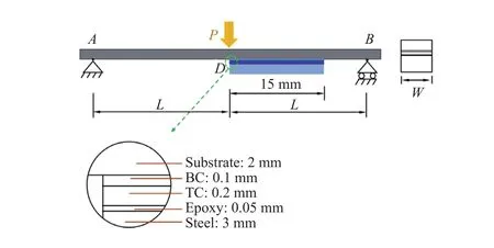
Fig. 1. Specimen shape and size for three-point bending tests. Point D is supposed to be the crack initiation position.
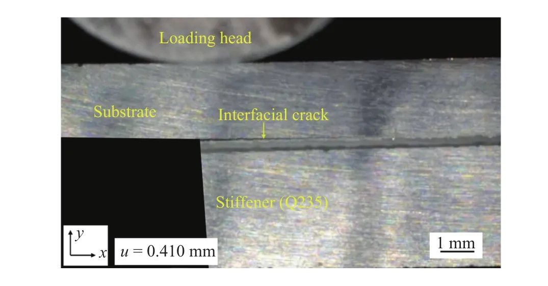
Fig. 2. Cross-sectional image of specimen with displacement of 0.410 mm, magnification is 30 times.
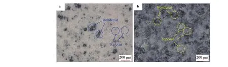
Fig. 3. Fractured surfaces of TBC specimen using optical microscope: (a) topcoat and (b) bondcoat.
The load–displacement relationship of TBC specimens under mechanical tests is shown in Fig. 4. Each data point was obtained from the average of five specimens. The curve of load–displacement can be divided into three stages. The first stage (OA)shows that the TBC specimens deform linearly with the applied load to accumulate strain energy for subsequent crack initiation.The load reaches a critical value with the magnitude of 152 N at point A, where the displacement of loading point is about 0.22 mm. Subsequently, the second stage (AB) starts with a sharp decrease load with the increase of displacement, and ends with the load of 133 N. Experimental observations indicate that intersplat delamination suddenly occurs at the TC/BC interface and the interface crack develops rapidly because of the instantaneous accumulating strain energy release. Finally, the loadPcontinues to get larger with the increase of the displacement of loading pointu, as shown in the third stage (BC). The interfacial crack propagated slowly and steadily during this stage, and cross-sectional images including the interfacial crack were obtained with the optical system, as shown in Fig. 2. Image processing software was using to identify the crack lengthl. Multiple tests were repeated and experimental data were averaged to estimate the uncertainties.
The fracture toughness is an important parameter to evaluate crack initiation and propagation. The energy provided by the system is equal to the energy dissipation in the form of crack propagation:

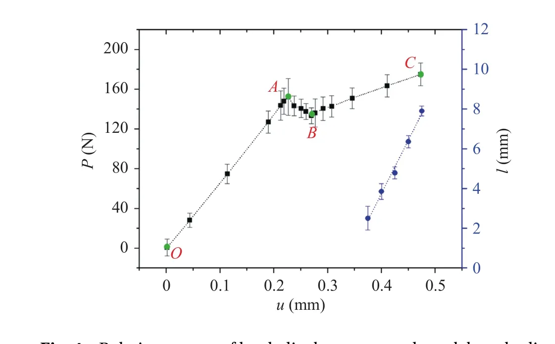
Fig. 4. Relation curves of load–displacement and crack length–displacement.
whereGis the strain energy release rate,Ris the energy dissipation,ΔAis the area of crack propagation. With the crack propagating, the potential energy of the system is reducing:

whereU1andU2are the energy of the system before and after crack propagation. Therefore, the strain energy release rate is
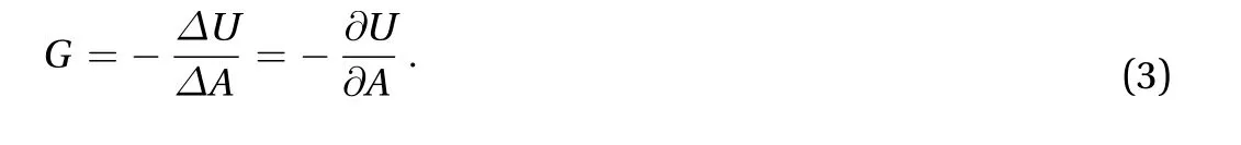
In the linear elastic case, the energy release rate is related to the compliance of a body or its overall stiffness, respectively. The fracture toughness takes the form [21]
whereWandlare the specimen width and crack length,respectively. The compliance of specimen,C, is expressed as

The compliance of each specimen can be obtained experimentally according to the relation betweenuandP. Values of fracture toughness of all the specimens were calculated. The compliance was obtained by the ratio ofuandP, and the relationship betweenCandlis shown in Fig. 5. The value ofcan be obtained by calculating the slope at different magnitude ofl. Theoretically, the adhesion energies of the TC/BC interface can be determined according to Eq. (4). According to the experiment, the measurement of crack length l was more reliable when the interfacial crack propagated slowly and steadily. Thus, the value ofis calculated based on the curve when crack length is larger than 6 mm, and the average value is 0.027 μm/(N·mm). Finally, the fracture toughnessGis obtained being of 77.1 J/m2. In the literature, the magnitude of energy release rate varies in the range of 17–260 J/m2[7, 10, 11, 19], and the present measured value for the ceramic 8YSZ coatings can be considered reasonable.
In summary, the adhesion of thermal spraying coatings deposited on a stainless substrate by the APS process was investigated experimentally. A modified three-point bending test was adopted to initiate and propagate the TC/BC interfacial crack.The adhesion energies of the TC/BC interface were determined based on the compliance of the structure, and the average value is 77.1 J/m2.
Compared with four-point bending test method, the proposed three-point bending method only generates a single interface crack and prevents practical difficulties in controlling equally propagating growth of cracks in four-point bending test.Furthermore, the specimen preparation is relatively simple and the test can be easily implemented with a good repeatability.
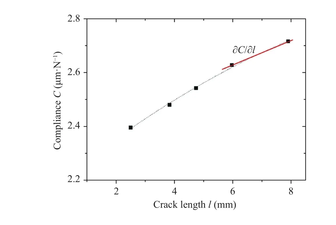
Fig. 5. Compliance versus crack length of TBC.
Acknowledgment
The authors are grateful for financial support from the National Natural Science Foundation of China (11232008,11372118, and 11672345), the Natural Science Foundation of Jiangsu Province (BK20161341), and the Six Talent Peaks Project in Jiangsu Province (2016-HKHT-004).
[1]N.P. Padture, M. Gell, E.H. Jordan, Thermal barrier coatings for gas-turbine engine applications, Science 296 (2002) 280–284.
[2]A.G. Evans, D.R. Mumm, J.W. Hutchinson, et al., Mechanisms controlling the durability of thermal barrier coatings, Prog. Mater. Sci. 46 (2001) 505–553.
[3]D. Zhu, K. Plucknett, Advances in Ceramic Coatings and Ceramic–Metal Systems: Ceramic Engineering and Science Proceedings, Vol. 26, Wiley-American Ceramic Society, 2008.
[4]J.G. Zhu, C. Wei, H.M. Xie, Simulation of residual stresses and their effects on thermal barrier coating systems using finite element method, Sci. China 58 (2015) 1–10.
[5]A. Kishi, S. Kuroda, T. Inoue, et al., Tensile test specimens with a circumferential precrack for evaluation of interfacial toughness of thermal-sprayed coatings, J. Therm. Spray Technol. 17(2008) 228–233.
[6]S.S. Kim, Y.F. Liu, Y. Kagawa, Evaluation of interfacial mechanical properties under shear loading in EB-PVD TBCs by the pushout method, Acta Mater. 55 (2007) 3771–3781.
[7]Z.H. Xu, Y. Yang, P. Huang, et al., Determination of interfacial properties of thermal barrier coatings by shear test and inverse finite element method, Acta Mater. 58 (2010) 5972–5979.
[8]M. Guerain, P. Goudeau, B. Panicaud, et al., Local stress determination in chromia-former thanks to micro-Raman spectroscopy: A way to investigate spontaneous delamination processes, J. Appl. Phys. 113 (2013) 142–150.
[9]Q. Chen, W.G. Mao, Y.C. Zhou, et al., Effect of Young’s modulus evolution on residual stress measurement of thermal barrier coatings by X-ray diffraction, Appl. Surf. Sci. 256 (2010)7311–7315.
[10]W. Zhu, L. Yang, J.W. Guo, et al., Determination of interfacial adhesion energies of thermal barrier coatings by compression test combined with a cohesive zone finite element model, Int. J.Plast. 64 (2015) 76–87.
[11]W.G. Mao, C.Y. Dai, L. Yang, et al., Interfacial fracture characteristic and crack propagation of thermal barrier coatings under tensile conditions at elevated temperatures, Int. J. Fract. 151(2008) 107–120.
[12]M.L. Benzeggagh, M. Kenane, Measurement of mixed-mode delamination fracture toughness of unidirectional glass/epoxy composites with mixed-mode bending apparatus, Compos. Sci.Technol. 56 (1996) 439–449.
[13]P. Charalambides, J. Lund, A. Evans, et al., A test specimen for determining the fracture resistance of bimaterial interfaces, J.Appl. Mech. 56 (1989) 77–82.
[14]Y.C. Zhou, T. Tonomori, A. Yoshida, et al., Fracture characteristics of thermal barrier coatings after tensile and bending tests,Surf. Coat. Technol. 157 (2002) 118–127.
[15]X.N. Li, L.H. Liang, J.J. Xie, et al., Thickness-dependent fracture characteristics of ceramic coatings bonded on the alloy substrates, Surf. Coat. Technol. 258 (2014) 1039–1047.
[16]I., Modified four-point bending specimen for determining the interface fracture energy for thin. brittle layers, Int. J. Fract. 92(1998) 213–220.
[17]Y. Yamazaki, A. Schmidt, A. Scholz, The determination of the delamination resistance in thermal barrier coating system by four-point bending tests, Surf. Coat. Technol. 201 (2006)744–754.
[18]P.Y. Théry, M. Poulain, M. Dupeux, et al., Adhesion energy of a YPSZ EB-PVD layer in two thermal barrier coating systems,Surf. Coat. Technol. 202 (2007) 648–652.
[19]P.F. Zhao, C.A. Sun, X.Y. Zhu, et al., Fracture toughness measurements of plasma-sprayed thermal barrier coatings using a modified four-point bending method, Surf. Coat. Technol. 204(2010) 4066–4074.
[20]L. Xu, H. Jing, L. Huo, Young’s modulus and stress intensity factor determination of high velocity electric arc sprayed metalbased ceramic coatings, Surf. Coat. Technol. 201 (2006)2399–2406.
[21]D. Gross, T. Seelig, Fracture Mechanics with an Introduction to Micromechanics, second ed., Springer, New York, 2011.
 Theoretical & Applied Mechanics Letters2018年1期
- Theoretical & Applied Mechanics Letters的其它文章
- A first order friction model for lubricated sheet metal forming
- On the generation of drift flows in wall-bounded flows transiting to turbulence Paul Manneville*
- The effect of fiber orientation on fracture response of metallic fiber-reinforced adhesive thin films
- Thermoelastic vibrations in a thin elliptic annulus plate with elastic supports
- Threshold characteristics of short-pulsed loads combined with the ultrasound field causing dynamic delamination of adhesive joints
- The interface of SiO2/ZnS films studied by high resolution X-ray photoluminescence