Optimization of Composites Shell Subjected to Hydrostatic Pressure to Maximize Design Pressure Factor
2018-01-04 08:25:03SHENKechunPANGuangSHIYao
船舶力學 2017年12期
SHEN Ke-chun,PAN Guang,SHI Yao
(a.School of Marine Science and Technology;b.Key Laboratory for Unmanned Underwater Vehicle,Northwestern Polytechnical University,Xi’an 710072,China)
Optimization of Composites Shell Subjected to Hydrostatic Pressure to Maximize Design Pressure Factor
SHEN Ke-chuna,b,PAN Guanga,b,SHI Yaoa,b
(a.School of Marine Science and Technology;b.Key Laboratory for Unmanned Underwater Vehicle,Northwestern Polytechnical University,Xi’an 710072,China)
This paper presented an optimization design of composites pressure hull subjected to hydrostatic pressure.An Optimization Platform was set up by interworking genetic algorithm and numerical analysis.The design pressure factor was considered as the objective function.Buckling and material failure were constraint conditions.Types of layup,fiber angle and ply number are optimized for Carbon/epoxy,Boron/epoxy and Glass/epoxy composites.The results revealed that the buckling pressure or the material failure pressure would restrict the design pressure for different kind of composites.Different types of layup impacted the design pressure factor significantly.Application of composite materials for deep-water pressure shell had more reserve buoyancy.Results of this study could provide a valuable reference for designers of underwater vehicles.And this paper suggests that new way of enhancement,such as variable thickness,composites ribs would be used to solve the conflict of buckling pressure and material failure pressure,and increase the smaller one to improve the design pressure.
hydrostatic pressure;composites pressure shell;optimization;buckling;failure
0 Introduction
Some three-quarters of the Earth’s surface are covered by water and only little of the ocean bottom has been explored.The greatest ocean depth of the oceans is 11.52 km.Most underwater vehicles can only dive to a depth of about 1 500 m which is much less than the average depth of the oceans that is between 4 000 and 5 000 m.
For an underwater vehicle in deep sea,reserve buoyancy is required for integral structure,and weight reduction is expected for more efficient performance.This can be easily met by applying composite materials.Composite materials have an excellent specific stiffness and strength to withstand very high external pressure,in addition,sound absorption and corrosion resistance are crucially important for underwater vehicles[1].When designing composites pressure vessel subjected to hydrostatic pressure,load carrying capacity is priority.Buckling andstatic material failure may be caused by insufficient rigidity and lack of strength.There has been considerable amount of work carried out on buckling analysis of composites material structures subjected to hydrostatic pressure.Moon[2]investigated the buckling behavior of filament-wound carbon/epoxy composite cylinders under external hydrostatic pressure through finite element analysis and testing.Maalawi[3]presented a mathematical model to enhance the buckling stability of composite cylinders under external pressure.Nguyan[4]studied the stability of the perfect cylindrical shell variable thickness by introducing the coupled linearized governing stability equation for cylindrical shell under the external pressure.Messager[5]maximized the stability limits of thin-walled laminated composite vessels for underwater vehicles.Lopatin[6]studied the buckling of the clamped-clamped sandwich cylindrical shell under uniform external pressure.As for the failure behavior of composites material pressure hulls,a number of papers are available.Tafreshi[7-8]studied the effect of delamination of composite cylindrical shells under external pressure employing the combined double-layer and single-layer of shell elements.Blachut[9]analyzed the first ply failure of composite toroidal pressure hull based on a single,symmetric lamination.Lee[10]optimized the design load of composite sandwich cylinder under external hydrostatic pressure considering the buckling and static material failure.
From reviewing on the previous studies,the literatures on analyzing the design pressure factor of filament-wound composite material pressure hulls subjected to hydrostatic pressure both considering the structural stability and material failure are rarely reported.Accordingly,an optimization of composite pressure hull for underwater vehicle was conducted for Carbon/epoxy,Boron/epoxy and Glass/epoxy composite.First,an optimization platform was set up to maximize the design pressure factor.Afterwards,the effects of design variables on buckling pressure,material failure pressure,and design pressure were analyzed.Next,the design pressure factors were achieved for three candidates composite material.Finally,according to the current results,new directions were pointed for the future research.
1 Analytical fundamentals
The structure model used to represent the composite laminated shell-structure is shown in Fig.1.The 1,2 and 3 are the principal directions of an orthotropic lamina,described as follows:
Direction 1 is principal fiber direction which is also called fiber longitudinal direction.Direction 2 is transversal direction which is in-plane direction perpendicular to fiber direction.Direction 3 is normal direction which is out-of-plane direction perpendicular to fiber direction.For any point P in the surface,the Radius vector is ρ.Parameters α and β are Gauss coordinate.where ρi(i=1, )
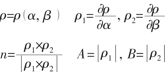
2 and n are base vector and normal vector;A and B are the Lamé parameters.
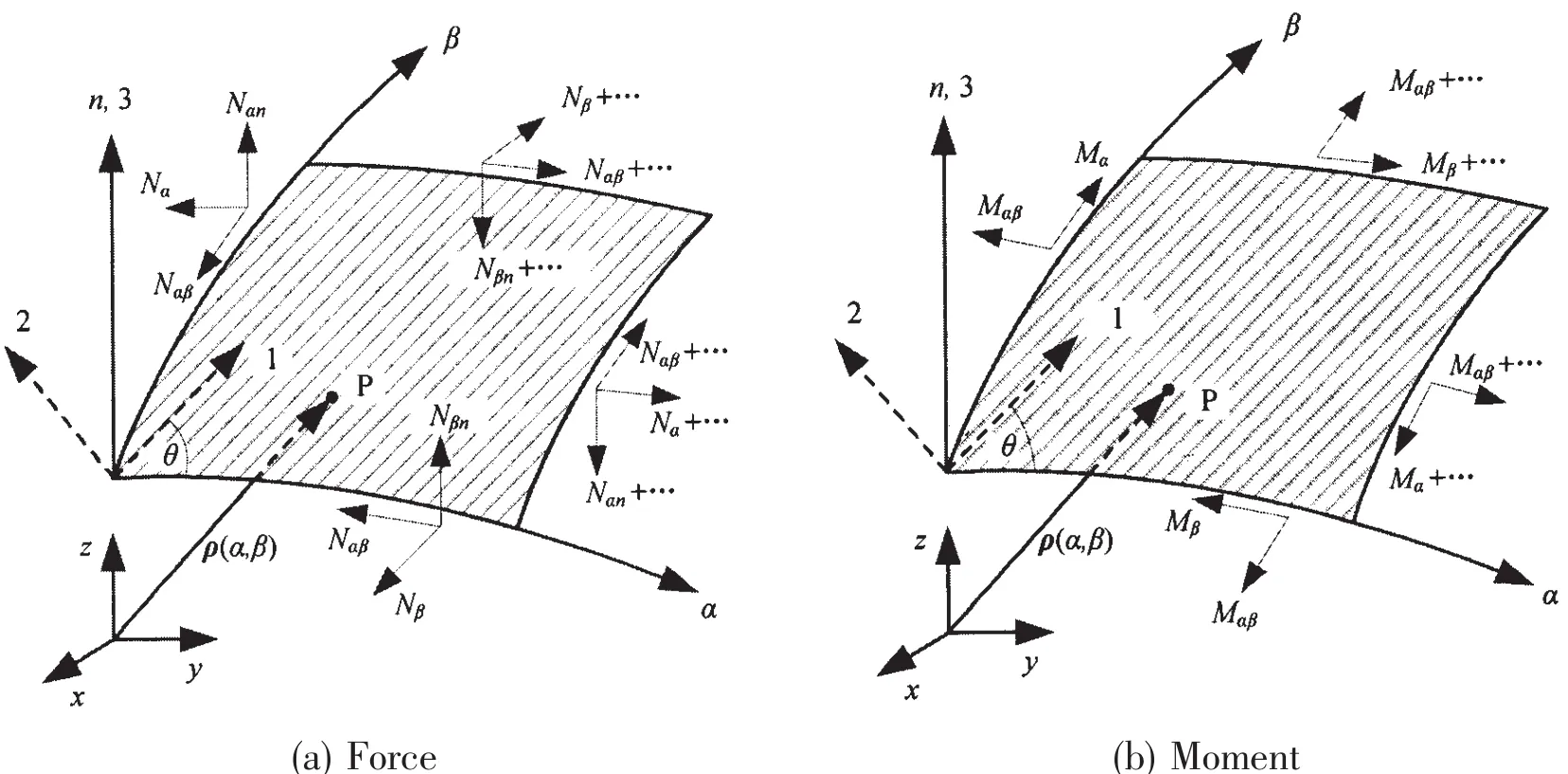
Fig.1 Gauss coordinate and components of force and moment
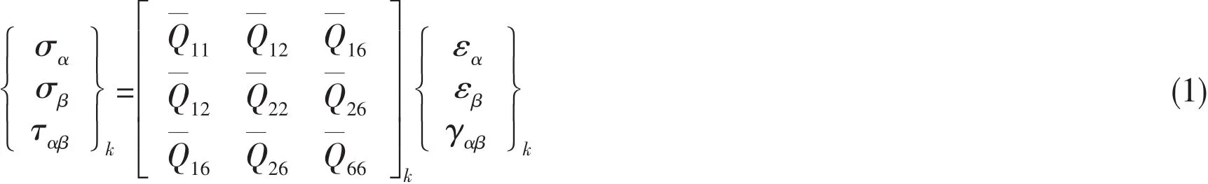
1.1 Constitutive equations
The classical lamination theory is applied to analyze the mechanical behavior of the composite laminate.As shown in Fig.1,the in-plane stress components are given by:
The elements of the kthtransformed reduced stiffness matrixis referred to the reference of the surface coordinates(α,β, )n and given in the following:
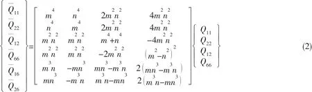
where m=cosθ,n=sinθ and θ is the fiber orientation angle of the laminate;Qijare related to the commonly known engineering constants(E11,E22,G12,ν12)and are described as follows:

Using Kirchhoff plate theory[11],the displacements of a material point at distance z from the middle surface are:
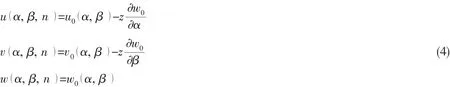
where u0,v0and w0are the displacements of a generic point(α, β )on the shell middle surface(z=0 )in α, β and n directions,respectively.The strain-displacement relations in terms of the middle surface strains and shell curvatures are stated as follows:
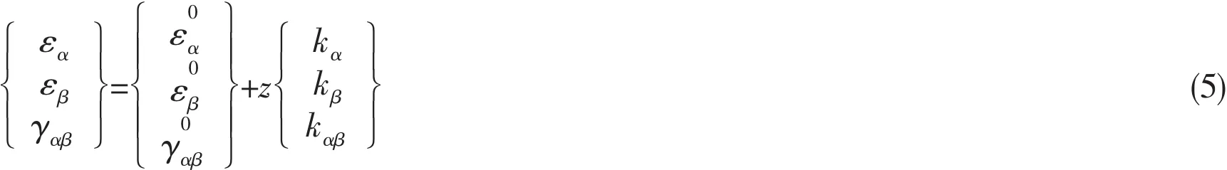
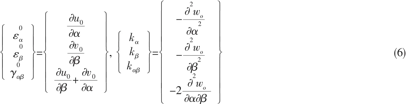
where the middle surface strains and curvatures are given as follows[12]:
The resultant forces and moments per unit length applied at the middle surface are obtained by the integrals:
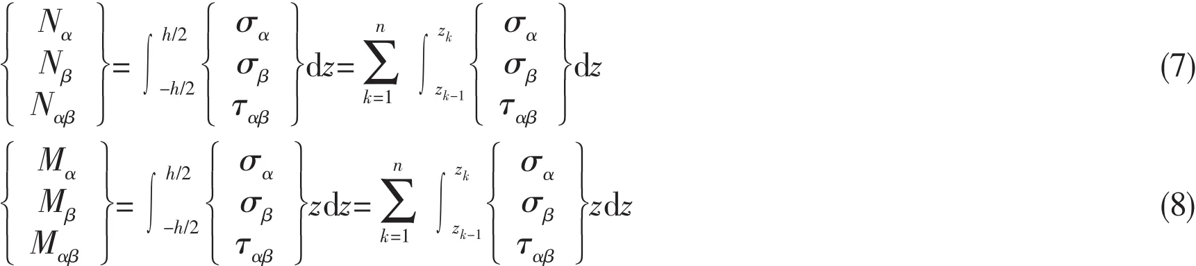
where h is the total shell thickness,n is the number of different layers in the stacking sequence,and zk(k=1,2,…,n )is the through thickness position of kthlayer from the middle surface.Substituting the stresses in terms of strains given by Eqs.(1)and(6)into Eqs.(7)and(8),we get:
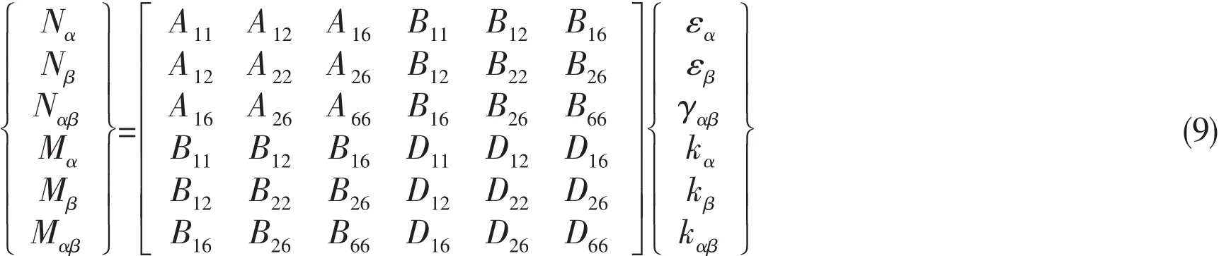
where Aij,Bijand Dijare called the extensional stiffness,coupling stiffness and bending stiffness,respectively and given as follows:

where tkis the thickness of the kthlayer.
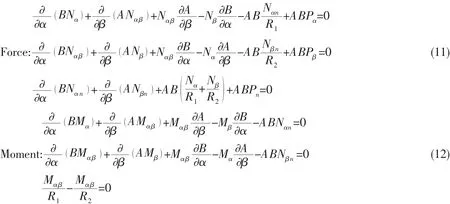
1.2 Equilibrium equations
Under the environment of hydrostatic pressure,P represents the hydrostatic pressure.Pi(i= α,β,n )are the components of hydrostatic pressure P in ρ1,ρ2(base vector)and n(normal vector)direction,respectively.The equilibrium equations of the shell under the hydrostatic pressure are stated as follows:
2 Optimum design of filament-wound composites pressure hull
2.1 Model description
As shown in Fig.2,the filament-wound composite shell model is generally composed of number of layers(2N)for both type A and type B stacking sequence.In this study,the design variables were the fiber angles(θi)and the corresponding number of layer.The given total number of layer was 2N(N=20,25,30,35),corresponding to the shell thickness t=8,10,12,14 mm.The objective of the optimization was to maximize the design pressure factor KP,which can be taken in the form of the following ratio KP=Pde/m.Pdeis design pressure,m is the mass of the pressure hull.In order to obtain the maximum design pressure factor KP,the maximum design pressure Pdemust be derived.For each given design variable θiand t,material failure pressure Pfand buckling pressure Pcrcomposed two feasible regions.The lower value between the two feasible regions composed the optimal feasible region,and the greatest pressure of the optimal feasible region became the optimum,i.e.the maximum design pressure.The maximum design pressure factor was stated as follows:
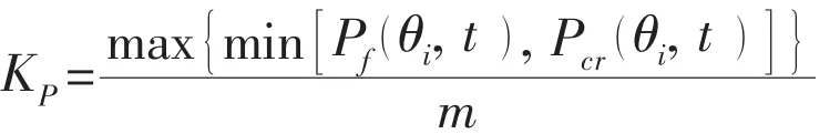

Fig.2 Design variables of the filament-wound composite pressure hull
The composites pressure vessel was constituted of cylindrical shell and hemispherical heads.The dimensions were as follows:an internal diameter of 300 mm and a length of 750 mm.ANSYS,a commercial program for finite element analysis,was used to for static analysis and buckling analysis.The Tsai-Wu failure criterion was used to assess the ability of composite cylindrical hull to withstand overstressing failure[13].SHELL281 element defined by eight nodes with six degrees of freedom at each node was used to mesh the pressure hull model.The nodes at each end of the finite element model were constrained translations in the y and z axes,and rotations in the axial direction i.e.the x axe.All nodes in the symmetry plane in the axial direction were restricted rotations about the x,y,z axes,and Ux=0.Carbon/epoxy,Boron/epoxy and Glass/epoxy composite materials were selected to analyze.The properties of the unidirectional composite prepreg were given in Tab.1.
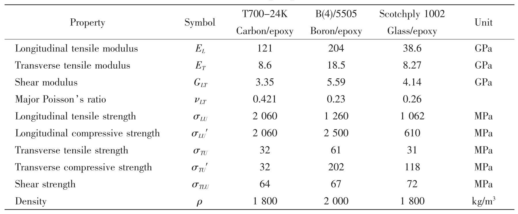
Tab.1 Material properties[2,14]
2.2 Optimization platform
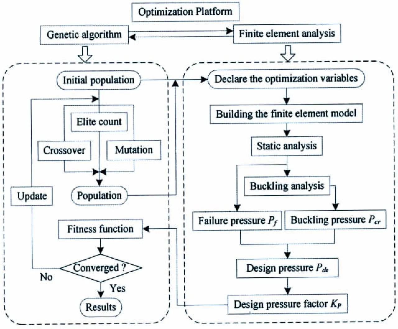
The optimization platform was set up by interworking genetic algorithm and finite element analysis shown in Fig.3.Firstly,an initial population was created,which was declared to the design variable for parametric modeling.Then,static analysis was conducted for material failure pressure,and then buckling pressure was achieved by stability analysis.The minor one was treated as design pressure.The design pressure factor was calculated as fitness function and returned to genetic algorithm.Repeat the above process until each individual in the initial population was analyzed.Crossover and mutation were conducted in the genetic operators,and Elite were chosen based on their fitness to obtain a new generation.Update population and conduct analysis like above cycle for ten generations and the design optimization was completed until the fitness function was converged.
3 Numerical results and discussion
For Carbon/epoxy composite-Type A(t=8 mm),the maximum design pressure was 13.5 MPa at[(±60°)8/(±45°)12]shown in Fig.6,which was determined by the failure pressure,because the buckling pressure was 15.32 MPa at that point.The buckling pressure and failure pressure are shown in Fig.4 and Fig.5,respectively.The maximum buckling pressure was 15.96 MPa at[(±60°)8/(±40°)12]whose failure pressure was 11.25 MPa,and the maximum failure pressure was 14.63 MPa at[(±35°)8/(±55°)12]and[(±40°)8/(±55°)12]whose buckling pressure was 11.13 MPa and 11.65 MPa,respectively;therefore,neither the maximum buckling pressure nor the maximum failure pressure was the maximum design pressure.
As for Boron/epoxy composite-Type A(t=8 mm),the buckling pressure,failure pressure and design pressure surfaces are shown in Figs.7-9,respectively.Overall,the failure pressure was higher than the buckling pressure except for some design variables in some corner areas.Although the maximum failure pressure of 70 MPa was found at[(±70°)8/(±40°)12],the corresponding buckling pressure was 23.01 MPa only.The maximum design pressure was determined by the maximum buckling pressure.The optimum pressure was 26.31 MPa at[(±60°)8/(±40°)12].
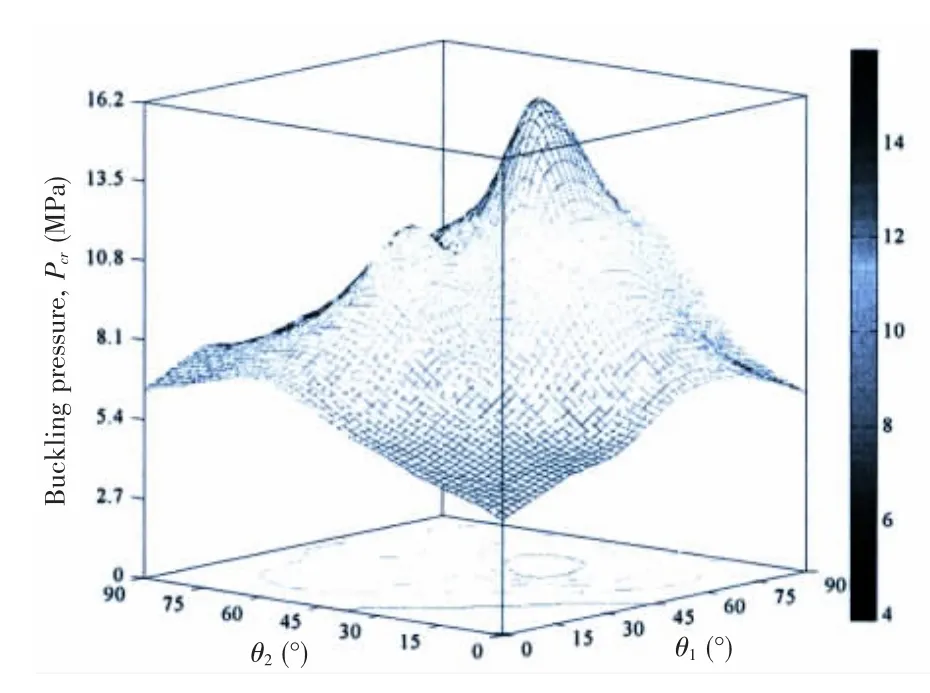
Fig.4 Buckling pressure of Carbon/epoxy composite-Type A(t=8 mm)
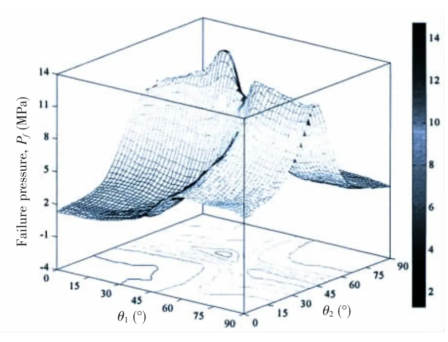
Fig.5 Failure pressure of Carbon/epoxy composite-Type A(t=8 mm)
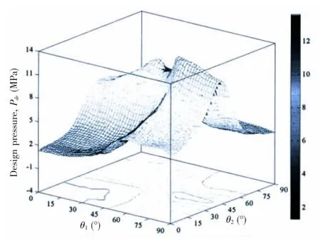
Fig.6 Design pressure of Carbon/epoxy composite-Type A(t=8 mm)
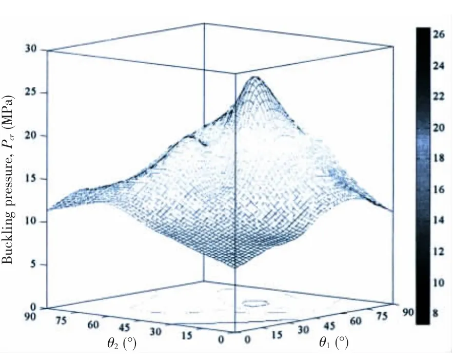
Fig.7 Buckling pressure of Boron/epoxy composite-Type A(t=8 mm)
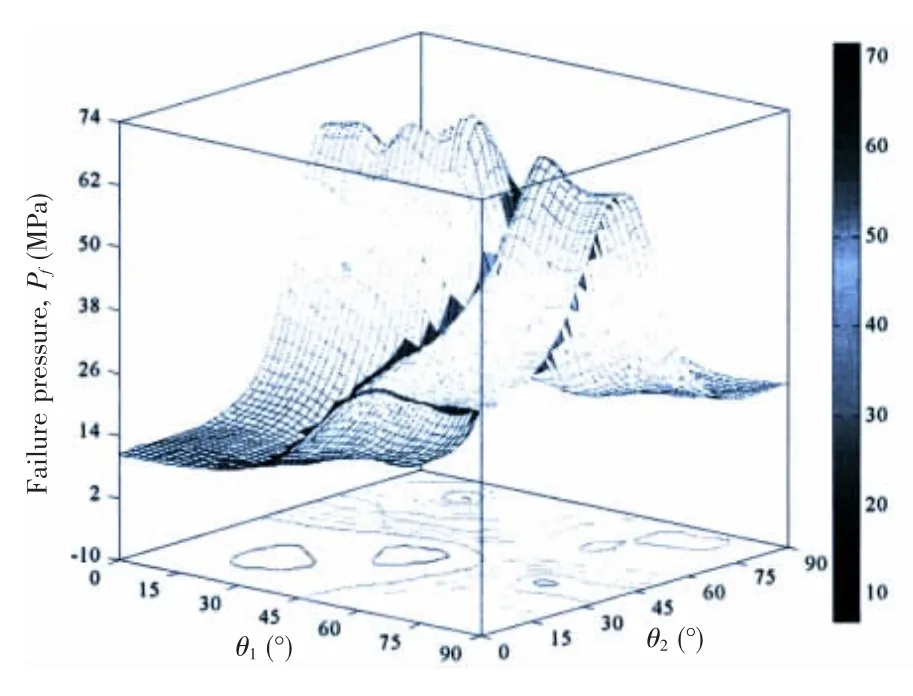
Fig.8 Failure pressure of Boron/epoxy composite-Type A(t=8 mm)
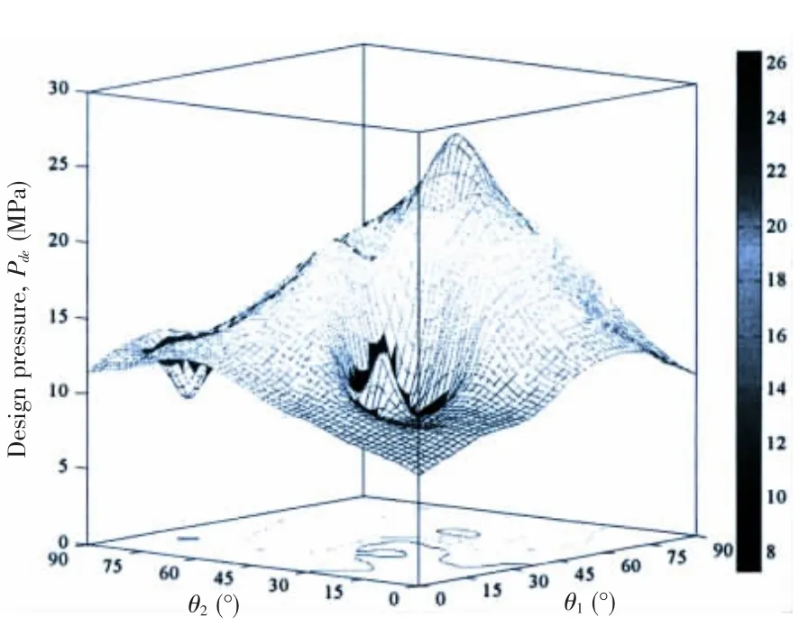
Fig.9 Design pressure of Boron/epoxy composite-Type A(t=8 mm)
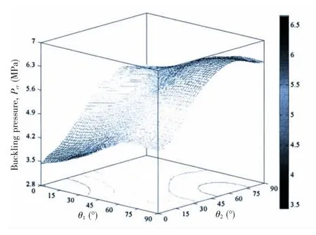
Fig.10 Buckling pressure of Glass/epoxy composite-Type A(t=8 mm)
Fig.11 Failure pressure of Glass/epoxy composite-Type A(t=8 mm)
Fig.12 Design pressure of Glass/epoxy composite-Type A(t=8 mm)
Fig.13 Buoyancy factor of metal alloys and composite material
For Glass/epoxy composite-Type A(t=8 mm),as shown in Figs.10-12,the material failure pressure was much higher than the buckling pressure all over the design variable.Therefore the design pressure surface was determined by buckling pressure,and the optimum pressure was 6.65 MPa at[(90°)3/(±65°)17].
The buoyancy factor KF=FB/m,reflecting the ratio of buoyancy and mass,was also considered.FBis the mass of fluid displaced by the body volume.As shown in Fig.13,the buoyancy factors were given,which had a downtrend for composite materials and metal alloys.Compared with metal alloy material,composite materials showed more ability to provide adequate buoyancy.This is very important for underwater vehicle.
The buckling,failure and design pressure for Carbon,Boron and Glass/epoxy composite for Type A and Type B(t=8,10,12,14 mm)were presented and summarized in Figs.14-19.After reviewing the optimum solution,it was concluded as follows:
For the three candidate’s composite materials,both the buckling pressure and material failure pressure increased significantly as the thickness of the pressure hull increased for both Type A and Type B.The growth rate of Type-B is higher than that of Type-A in varying degree.
Fig.14 Carbon/epoxy composite-Type A
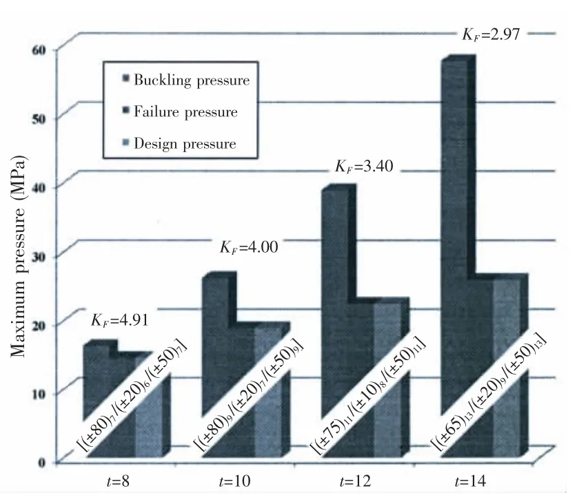
Fig.15 Carbon/epoxy composite-Type B

Fig.16 Boron/epoxy composite-Type A
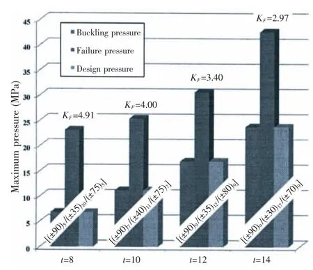
Fig.18 Glass/epoxy composite-Type A
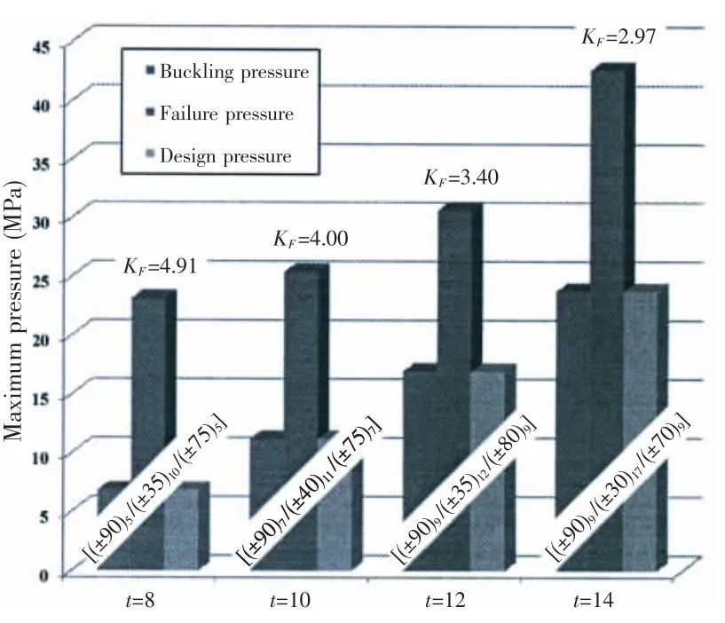
Fig.19 Glass/epoxy composite-Type B
For Carbon/epoxy composite,the growth rate of buckling pressure is obviously higher than that of material failure pressure;therefore the material failure pressure determined the design pressure.For Boron/epoxy composite,the material failure pressure is larger than buckling pressure,so the bucking pressure determined the design pressure except the thickness of pressure hull equaling to 14 mm.For Glass/epoxy composite,the growth rate of material failure pressure is obviously higher than that of buckling pressure,so the bucking pressure determined the de-sign pressure.That is contrary to Carbon/epoxy composite.
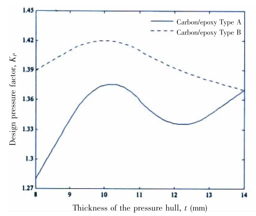
Fig.20 Design pressure factor of Carbon/epoxy composite
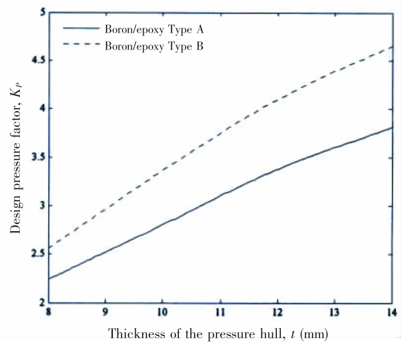
Fig.21 Design pressure factor of Boron/epoxy composite
The results of design pressure factor were shown in Figs.20-22.From the analysis of the data,Type B showed more obvious advantages than Type A in mass efficiency.To be more specific,for Carbon/epoxy composite,the optimum design pressure factor showed volatility,and got the maximum value at the t=10 mm.For Boron/epoxy composite,the optimum design pressure factor showed solid growth as the thickness of the pressure hull increased.For Glass/epoxy composite,the mass efficiency was the lowest in the three candidate’s composite material.
4 Conclusions
Two types of layup including[(±θ1)m/(±θ2)N-m]and[(±θ1)m/(±θ2)N-2m/(±θ3)m]were optimized for three candidate’s composite material.Applying the optimization platform,both buckling behavior and material failure were investigated to maximum the design pressure factor for composites pressure hull under external hydrostatic pressure.In the process of optimization,buckling pressure,material failure pressure and design pressure were analyzed for various values of design variables.The effects of thickness of pressure hull on buoyancy factor were also evaluated.Two kinds of metal alloys were analyzed to compare with the three candidate’s composite material.The following observations were made:
Either buckling pressure or material failure pressure may determine design pressure for the three candidate’s composite material.For Carbon/epoxy composite,material failure re-stricted design pressure seriously.But on the contrary for Boron/epoxy and Glass/epoxy composite,buckling pressure determined design pressure.
Types of layup had a significant impact on design pressure factor.Detailed speaking,type of layup[(±θ1)m/(±θ2)N-2m/(±θ3)m]increased the value of design pressure factor in varying degrees,compared with type of layup[(±θ1)m/(±θ2)N-m].As mentioned above,similar situation happened on the buckling pressure,material failure pressure and design pressure.
Through the analysis of the buoyancy factor,composite material provided sufficient reserve buoyancy.That makes the underwater vehicle have good carrying capacity.Compared with applying metal alloys,applying composite material may reduce the size of underwater vehicle because of no need to fill large amount of buoyancy material.
Because of the excellent performance,composite material has been widely applied in ocean structures.The results presented in the paper can serve as a valuable reference in design of underwater vehicle.However,to dive into deeper sea,the conflict of buckling pressure and material failure should be resolved.New way of enhancement,variable thickness,ribs or metal embedded would be effective methods,and the relevant research works would be conducted.Especially,the failure theory and criterion of composite pressure shell under the hydrostatic pressure would be the top priority.
Acknowledgement
This work was supported by the National Natural Science Foundation of China(Grant Nos.51479170 and 11502210)and National Key R&D Program(Grant No.2016YFC0301300).
[1]Ross C T F.A conceptual design of an underwater vehicle[J].Ocean Engineering,2006,33(16):2087-2104.
[2]Moon C J,Kim I H,Choi B H,et al.Buckling of filament-wound composite cylinders subjected to hydrostatic pressure for underwater vehicle applications[J].Composite Structures,2010,92(9):2241-2251.
[3]Maalawi K Y.Use of material grading for enhanced buckling design of thin-walled composite rings/long cylinders under external pressure[J].Composite Structures,2011,93(2):351-359.
[4]Nguyen H L T,Elishakoff I,Nguyen V T.Buckling under the external pressure of cylindrical shells with variable thickness[J].International Journal of Solids and Structures,2009,46(24):4163-4168.
[5]Messager T,Pyrz M,Gineste B,et al.Optimal laminations of thin underwater composite cylindrical vessels[J].Composite Structures,2002,58(4):529-537.
[6]Lopatin A V,Morozov E V.Buckling of the composite sandwich cylindrical shell with clamped ends under uniform external pressure[J].Composite Structures,2015,122(122):209-216.
[7]Tafreshi A.Delamination buckling and postbuckling in composite cylindrical shells under external pressure[J].Composite Structures,2004,42(10):1379-1404.
[8]Tafreshi A.Delamination buckling and postbuckling in composite cylindrical shells under combined axial compression and external pressure[J].Compos Struct,2006,72:401-418.
[9]Blachut J.Buckling and first ply failure of composite toroidal pressure hull[J].Computers&Structures,2004,82(23):1981-1992.
[10]Lee G C,Kweon J H,Choi J H.Optimization of composite sandwich cylinders for underwater vehicle application[J].Composite Structures,2013,96(4):691-697.
[11]Simitses G J,Hutchinson J W.An Introduction to the elastic stability of structures[M].Prentice-Hall,1976.
[12]Brush D O,Almroth B O.Buckling of bars,plates,and shells[M].US:McGraw-Hill Inc.,1975.
[13]Tsai S W,Hahn T H.Introduction to composite materials[J].West Port:Technomic Publishing Company,1980,68(3):331-332.
[14]Liang C C,Chen H W,Jen C Y.Optimum design of filament-wound multilayer-sandwich submersible pressure hulls[J].Ocean Engineering,2003,30(15):1941-1967.
靜水壓力下纖維纏繞復合材料殼體耐壓因子的優化設計
沈克純a,b, 潘 光a,b, 施 瑤a,b
(西北工業大學a.航海學院;b.無人水下運載技術重點實驗室,西安 710072)
基于遺傳算法和數值分析一體式優化平臺,以設計壓力因子為目標函數,結構失穩和材料靜強度破壞為約束條件,纖維纏繞策略和鋪層方式為變量,對靜水壓力作用下碳/環氧、硼/環氧和玻璃/環氧等三種復合材料殼體的耐壓因子進行優化設計。結果表明,復合材料耐壓殼體在深海環境下能夠提供充足的正浮力;對于不同的復合材料,最大設計壓力受限的因素有所不同,主要受限于結構失穩或材料強度破壞;纖維纏繞策略和鋪層方式對設計壓力因子具有顯著影響。文中最后提出變厚度設計、復合材料肋骨等增強方式,旨在解決結構失穩或材料強度破壞對最大設計壓力的限制,研究成果可為復合材料耐壓殼體結構設計提供參考。
靜水壓力;復合材料殼體;優化設計;失穩;破壞
U663.1
A
國家自然科學基金資助項目(51479170,11502210);國家重點研發計劃(2016YFC0301300)
沈克純(1987-),男,西北工業大學博士研究生;
潘 光(1969-),男,西北工業大學教授,博士生導師;
施 瑤(1988-),男,西北工業大學講師。
U663.1 Document code:A
10.3969/j.issn.1007-7294.2017.12.010
date:2017-09-01
Supported by the National Natural Science Foundation of China(Grant Nos.51479170 and 11502210);by the National Key Research and Development Program(Grant No.2016YFC0301300)
Biography:SHEN Ke-chun(1987-),male,Ph.D.student of Northwestern Polytechnical University,E-mail:shenkechun@126.com;PAN Guang(1969-),male,professor/tutor,correponding author;E-mail:panguang601@163.com;SHI Yao(1988-),male,lecturer,E-mail:nh880408@gmail.com.
1007-7294(2017)12-1551-13
猜你喜歡
房地產導刊(2022年5期)2022-06-01 06:20:14
建材發展導向(2021年12期)2021-07-22 08:06:48
建材發展導向(2021年7期)2021-07-16 07:07:52
中學生數理化(高中版.高二數學)(2021年12期)2021-04-26 07:43:48
藝術啟蒙(2018年7期)2018-08-23 09:14:18
纖維復合材料(2018年3期)2018-04-25 07:22:58
電子測試(2017年11期)2017-12-15 08:57:13
海峽姐妹(2017年7期)2017-07-31 19:08:17
Coco薇(2017年5期)2017-06-05 08:53:16
應用化工(2014年10期)2014-08-16 13:11:29

- 船舶力學的其它文章
- A New Method for Fast Estimation of Collision Dissipated Energy and Its Application in Ship-Platform Collision Accident
- Experimental Study on Strength and Fatigue of Sandwich Composite L-joint under Bending
- Fatigue Analysis for Welded Joints of Offshore Wind Turbine under Three Wind Loads
- Algorithm Simulation of Ship Dynamic Positioning Using Adaptive Fading Memory Filter
- Enhanced Extinction Curve Method for Roll Damping Estimation
- Numerical Predictions of the PPTC Propeller Tip Vortex Cavitation in Uniform Flow