Experimental Study on Strength and Fatigue of Sandwich Composite L-joint under Bending
2018-01-04 08:25:02ZENGHaiyanYANRenjunLinGUISiyuan
船舶力學 2017年12期
關鍵詞:復合材料
ZENG Hai-yan,YAN Ren-jun,Xü Lin,GUI Si-yuan
(a.Key Laboratory of High Performance Ship Technology,Ministry of Education;b.School of Transportation,Wuhan University of Technology,Wuhan 430063,China)
Experimental Study on Strength and Fatigue of Sandwich Composite L-joint under Bending
ZENG Hai-yana,b,YAN Ren-juna,b,Xü Linb,GUI Si-yuanb
(a.Key Laboratory of High Performance Ship Technology,Ministry of Education;b.School of Transportation,Wuhan University of Technology,Wuhan 430063,China)
Sandwich composite L-joints,comprising E-glass plain woven skins and PVC foam core,are designed and tested under both static and cyclic loading.Three specimens were tested statically to failure to obtain the maximum load-carrying capacity of the L-joint.Nine specimens were tested under cyclic load at three load levels.Load-life(S-N)curves are established by sigmoid and linear fitting,respectively.The study shows that the sigmoid function has higher accuracy and is recommended for life prediction.The maximum service load based on the sigmoid function is determined to be 9.30 kN.Failure mode analysis of the L-joint failed in fatigue test is made,including debonding between skins and foam core,delamination and fiber breakage.Propagation process of crack is divided into three stages:small crack initiates where ‘stress whitening’exists;crack propagates along the thickness direction of the arc bracket;crack covers the section of arc bracket indicating the failure of the joint.Degradation of the stiffness in fatigue is represented by a power function.The rate of stiffness degradation grows with the load level.
sandwich composites;fatigue life;L-joints;stiffness degradation;S-N
0 Introduction
Sandwich composites have been extensively used in aerospace,automotive and marine engineering for their unique advantages.For the configuration of sandwich composites,the composite skins with higher modulus and thinner thickness,are designed to bear tensile and compression loads.While the role of the soft and thick core is to separate skins and transfer shear loads.A large number of studies have been published focusing on the static strength of sandwich structures[1-5].It can be noted that the theoretic analysis,numerical simulation and experimental investigation are all used to predict the load-carrying capacity and failure behavior of sandwich beams,panels and joints.For actual engineering structures,basic strength requirements are first concerns of designers and easy to be satisfied.It is noteworthy that structural safety must be ensured under both static and cyclic loads.Consequently,structural behavior under cyclic loading is of great significance to ensure safety during the service life.
Studies[6-8]have shown that the fatigue behavior of composite laminates is quite different from that of metal materials,including failure modes and damage growth.Fiber fracture,matrix damage,delamination and fiber-matrix interface damage are the main failure modes for fiber reinforced fabrics.Besides,instead of the single crack for metal structure,microcracks spread all over the composites.Therefore,there is no clear law which can be used to explain the crack growth.Considering the fact that laminates only act as skins,extra complexity for fatigue analysis of sandwich composites is attributed to core material and the interaction between the two parts.
Fatigue behaviors of sandwich beams under flexural loading have attracted much attention.It has been shown that core shear failure is the typical failure mode under such conditions[9-13].Researches for factors that affect fatigue performance have been carried out as well,including load amplitude[14],core density and loading frequencies[15]and stress ratio[16-17].Theories used to predict fatigue life are similar to those for laminates,namely S-N curve and cumulative damage method.S-N curves for sandwich beams under bending have been presented in Refs.[18-19]based on test results.And studies by Bahram et al[20]and Manujesh and Rao[21]have shown the expressions for stiffness degradation during loading process.
It can be seen that most researches are carried out for sandwich beams based on experimental studies,owing to the lack of thorough understanding for sandwich structures.Whereas during structure design process,great attention should be paid to the performance of joints,where usually high level stress exists.Under such circumstance,joints are vulnerable to fatigue failure when subjected to cyclic load.For ship structures,load transfer between side plate and deck is achieved by means of L-joint configuration.For this purpose,this paper investigates the static and fatigue performance of sandwich L-joints with PVC foam core and glass fiber composite skins.Static experiment is conducted to obtain the failure load which is used to decide fatigue load amplitude later in the fatigue experiment.Given the fact that sandwich joints perform differently from sandwich beams,the failure mode is expected to be discussed in details.The aim of this paper is to deal with fatigue life of the sandwich L-joint,as well as the stiffness degradation during loading process.
1 Experimental study
1.1 Specimens
Two 1 000×500×33 mm plates were joined together at 105 angles with stiffeners on bottom skins,as can be seen in Fig.1.270 mm-long solid laminates were designed out of the consideration of constraint and load applying.And for sandwich plates,the thickness of composite skins and core was 4 mm and 25 mm respectively.The area with the length of 50 mm between solid laminate and sandwich plate acted as the transition zone.Two transversal stiffeners covered all the width of plates and longitudinal stiffeners were connected by the arc bracket and extended to the constrained area.Total thickness of stiffeners was 40 mm,with 34 mm-thick core sandwiched between two 3 mm-thick skins.The 5 mm-thick laminate was attached on the side of stiffeners and bracket.
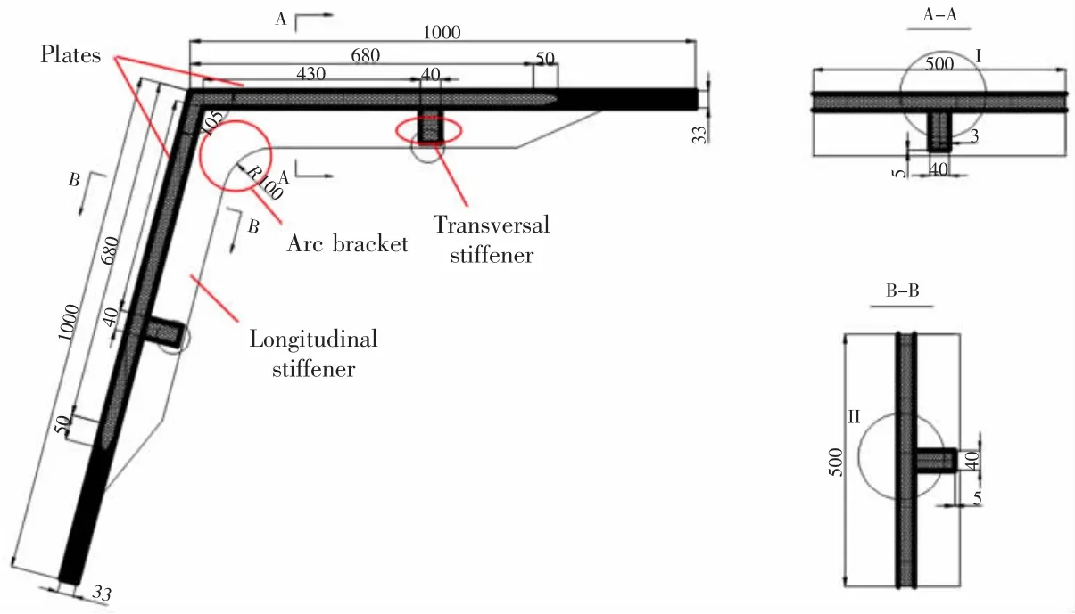
Fig.1 Illustration of L-joint
1.2 Materials
The studied sandwich structure consisted of PVC foam core and glass fiber reinforced plastic(GFRP)skins.The core used in this study was the cross-linked cellular foam Strucell P100,with the density of 100 kg/m3.The core was bonded to the laminates by EL-4300LV resin.The laminates were bidirectional woven E-glass fabrics with approximately equal amount of fibers in two main directions.
1.3 Test procedure
All specimens were loaded by a±250 kN servo hydraulic testing machine(MTS 322).As shown in Fig.2,load was exerted on the top plate of the steel fixture,to which samples were bolted.The whole structure was supported and fixed on the test platform by 4 bolts.Fig.3(a)-(c)shows the figure taken during test preparation from different views.
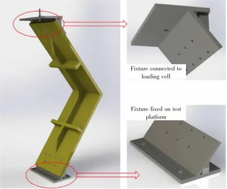
Fig.2 Test setup schematic
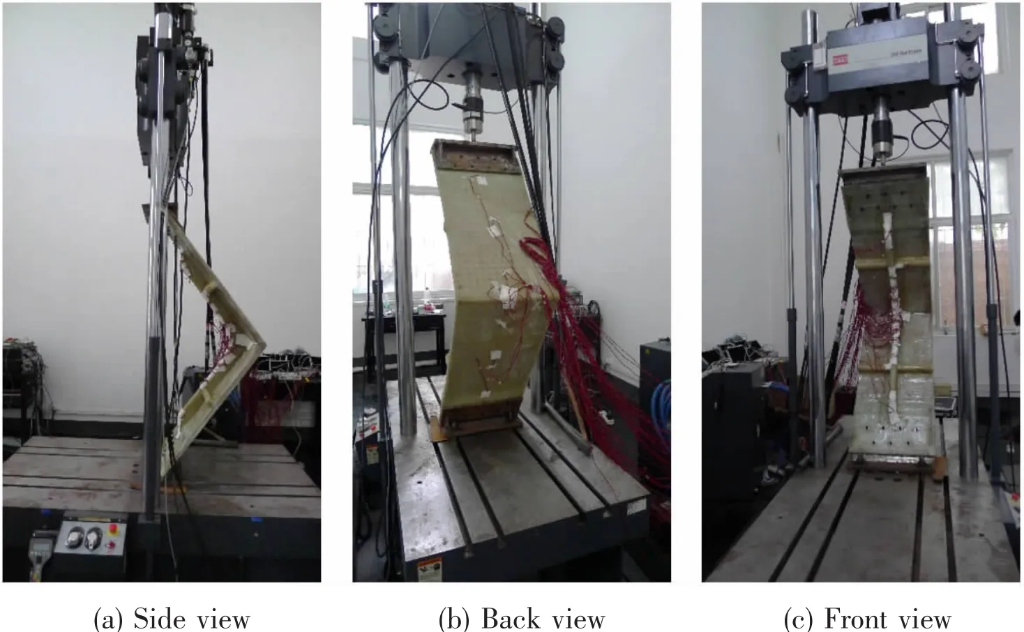
Fig.3 Figures from test
Three specimens(S1-S3)were first tested statically to failure.And the ultimate static capacity of the sandwich L-joints,P0,was estimated by the mean value of the loads obtained for specimens S1-S3.The maximum loads used in the fatigue test for specimens F1-F9 were listed in Tab.1,which were the load levels that joints might encounter during serving life.The stress ratio was set to 0.1 and sinusoidal load was conducted at a rate of 1.5 Hz.For all the tested specimens,the load and displacement of the cross-head were recorded to determine initial and subsequent stiffness.
2 Results and discussion
A summary of experimental results for ultimate loads of specimens S1-S3 and load cycle numbers of specimens F1-F9 is listed in Tab.1.
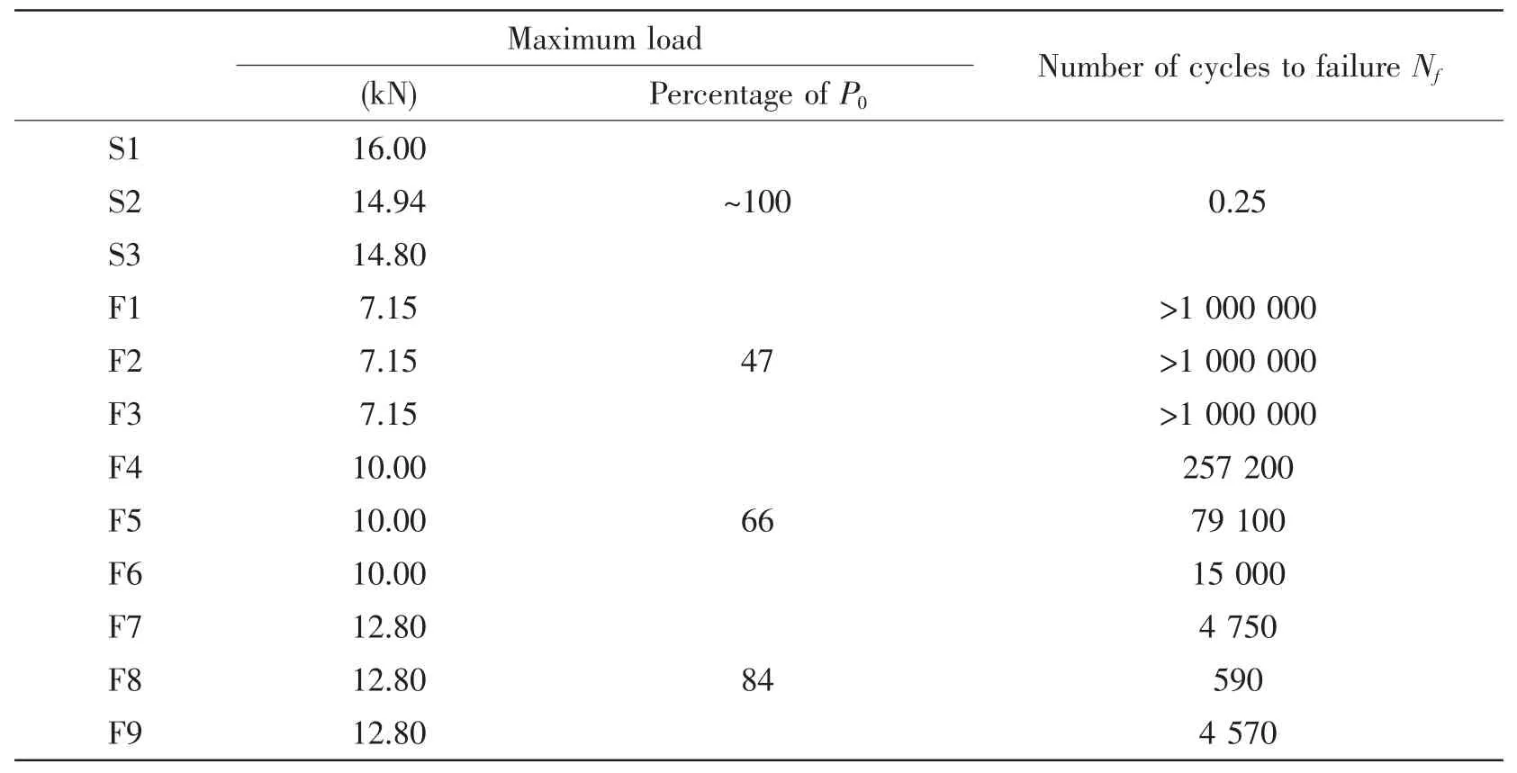
Tab.1 Summary of experimental results
2.1 Static test(S1-S3)
Load-deflection curves for static test specimens S1-S3 are shown in Fig.4.The average ultimate load was 15.25 kN,which was considered as upper loading level of fatigue tests.It was observed that for all specimens,load increased linearly with displacement until a sudden drop showed up.There was a sudden noise at the time of complete failure.All specimens experienced similar failure based on observation,as shown in Fig.5(a)-(c).Failure occurred within the arc bracket area and was characterized by a main crack running through the section.Localized‘stress whitening’ existed near the crack.
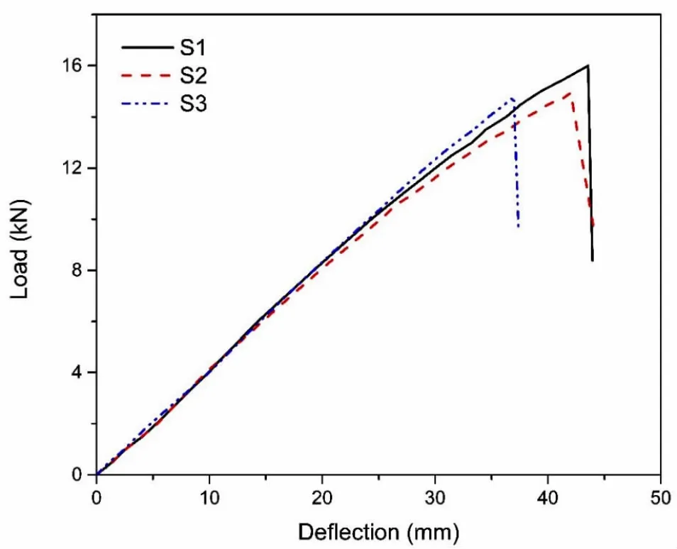
Fig.4 Load-deflection curves for specimens S1-S3
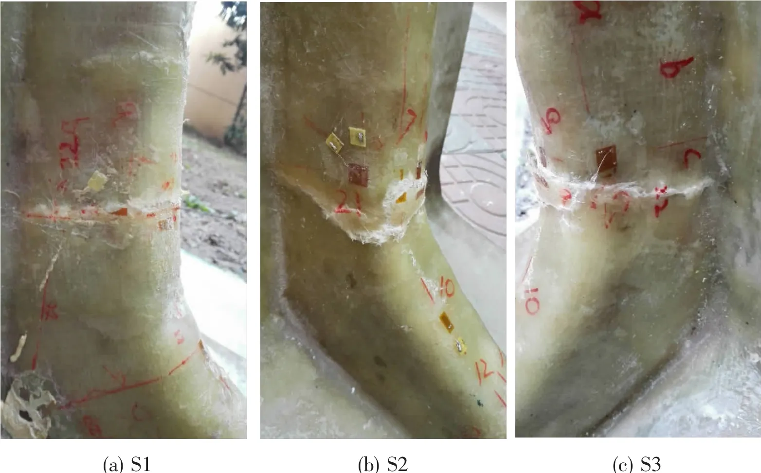
Fig.5 Specimens S1-S3 after failure
2.2 Flexural fatigue test(F1-F9)
2.2.1 Experimental phenomena and failure mode
Fatigue tests were performed on the specimens F1-F9 at different load levels,as listed in Tab.1.For specimens F1-F3,steady loading process was soon achieved after first several cycles,which was different from observations for other specimens subjected to higher load level.For specimens F4-F9,slight sound existed in the initial stages of cyclic loading and the sound disappeared after several cycles.No visible cracks were observed on specimens for most of its fatigue life,although localized ‘stress whitening’appeared within the arc bracket area.Shortly before failure,cracks formed at the positon where exactly the ‘stress whitening’ existed before.And the small crack propagated along the thickness direction of the arc bracket.Then the crack expanded along the height direction and eventually grew into a larger dominant crack running through the section during the final stages.At this time,a rapid decrease in the load carrying capacity occurred,which was defined as fatigue failure.Corresponding number of cycles to failure was recorded as the fatigue life Nf.Propagation process of crack is presented in Fig.6(a)-(c).
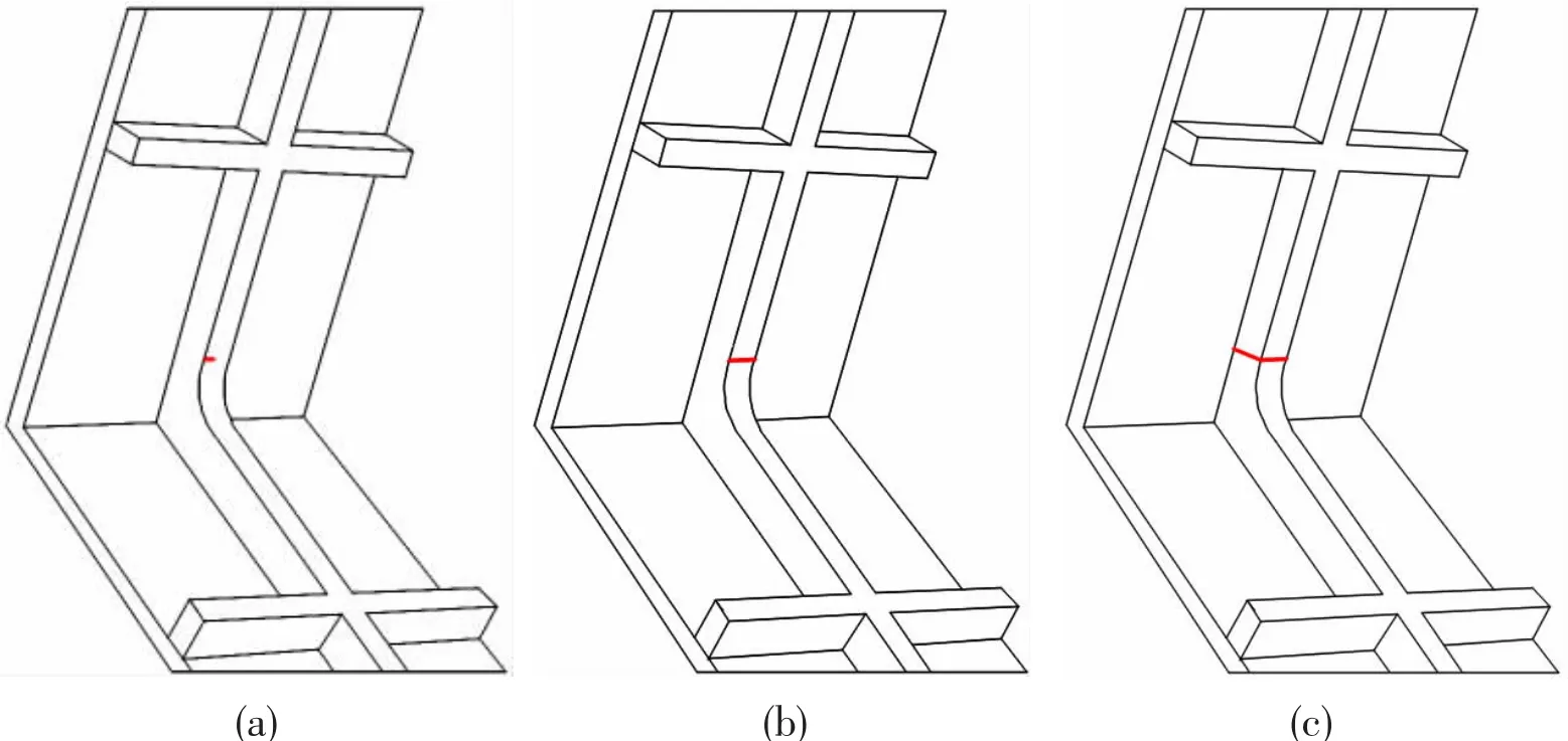
Fig.6 Propagation process of crack:(a)Small crack initiated;(b)Crack propagated along the thickness direction of the arc bracket;(c)Crack covered the section of arc bracket
Fig.7(a)-(c)shows specimens after fatigue tests.For specimens F1-F3,there were no cracks after 1000 000 load cycles.In this case,it was considered that fatigue failure did not not occur under this load level during the whole service life.For specimens that failed under fatigue tests,the location of cracks was similar to that of specimens under static tests.
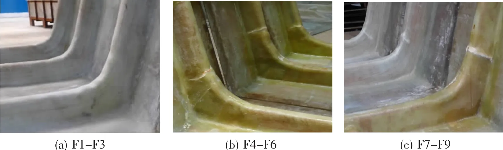
Fig.7 Specimens after fatigue tests
Internal damages can not be observed by external inspection,therefore small blocks with crack were cut from the joints to reveal the internal damage state.Debonding between skins and foam core,delamination and fiber breakage can be seen in Fig.8(a)-(c).Based on the observation on crack growth during fatigue test and internal situation of cutting blocks,failure mode analysis of the L-joint is made as follows:
(1)Debonding failure between the skin and foam core occurred within the arc bracket area;
(2)Delamination failure occurred in the skins which were completely separated from the foam core;
(3)‘Stress whitening’appeared on the outside surface of the arc bracket.After a certain number of cycles,crack resulted from fiber breakage initiated and propagated to failure in the way presented in Fig.6(a)-(c).
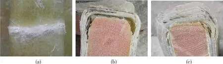
Fig.8 Failure modes:(a)Fiber breakage;(b)Debonding between skin and foam core;(c)Delamination
2.2.2 S-N curve for sandwich L-joints
One of the most straightforward ways to predict the fatigue life is the S-N diagram[22]and at present there is no standard form for composites,making it not easy to select the curve type.It is generally assumed that the ideal S-N curve is the one that most fits the experimental data.For fatigue tests done in this study,stress ratio and loading frequency were fixed.Therefore,models selected to fit the experimental data were expressed by maximum load and the number of cycles after which the L-joints failed.Results used for curve fitting were from specimens S1-S3 and F4-F9.The static experiment process was considered as 0.25 cycle of the loading.Specimens F1-F3 were used to validate the fitting curves as they did not fail after 1000 000 cycles.Fig.9(a)gives the results.
The solid line in Fig.9(a)represents the load-life relation expressed reported by Hale Mathieson and Amir Fam[16-17]for sandwich panels:

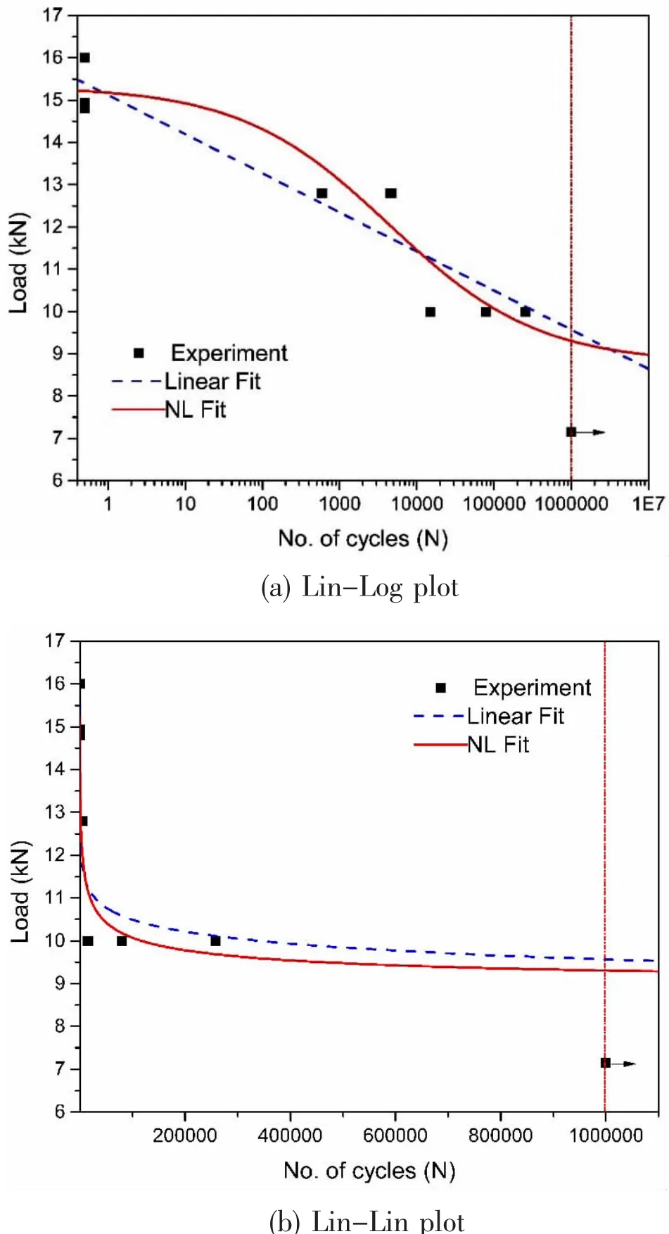
Fig.9 Fatigue data
where Pmaxis the maximum load and Nfis the number of cycles.a1,a2,a3and a4are constants.
The equation obtained from data points is:
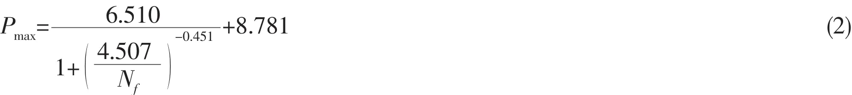
And the coefficient of determination(COD)R2is 0.905.Due to the scattered properties of composite materials,it can be assumed that fitting curve with determination coefficient R2≥0.85 is acceptable for fatigue life prediction.Based on Eq.(2),the load threshold for fatigue life exceeding 1 000 000 is 9.30 kN.The ultimate load with Nf=0.25 predicted by Eq.(2)is 15.21 kN,which is consistent with the average ultimate load 15.25 kN.
The dashed line shows the liner relation in a semi-logarithmic plot,which can be written as

where F is the maximum load and Nfis the number of cycles.C and D are constants.
Based on the fitting results from experimental data,Eq.(3)can be written as:

The coefficient of determination R2is 0.870.Based on Eq.(4),the load threshold for fatigue life exceeding 1 000 000 is 9.67 kN.The ultimate load with Nf=0.25predicted by Eq.(4)is 15.40 kN,which is slightly higher than the average ultimate load 15.25 kN.
Both load-life curves in Fig.9(a)are typical for structural material and show the characteristic that fatigue life decreases with increased load.These two curves are plotted in Lin-Log coordinate system.When curves are plotted in a Lin-Lin coordinate systemas shown in Fig.9(b),the fatigue life sharply increases with the decreased maximum load at first for both curves.And curves become flatter during 300 000 cycles to 1 000 000 cycles.When the number of cycles exceeds 1 000 000,curves remain constant approximatively.Combined with the actual service conditions of the L-joint,1 000 000 is set as the fatigue life requirement.For specimens F1-F3,the applied maximum load 7.15 kN is lower than the threshold load predicted by the curves,which are 9.30 kN and 9.67 kN for Eq.(2)and Eq.(4),respectively.Therefore,under this load level,there is no fatigue failure.
Results given by the two fitting curves are close.The curve represented by Eq.(2)has higher determination coefficient than that represented by Eq.(4).And the load threshold for cycles of 1 000 000 and ultimate load predicted by Eq.(2)are both lower than values predicted by Eq.(4).For the ultimate load,Eq.(2)has higher accuracy when compared with the average value by static tests.And in order to ensure the safety during service,it is reasonable to take the more conservative load(9.30 kN)as the upper limit of load to meet the fatigue life requirement.Based on these considerations,Eq.(2)is recommended for L-joints in this study.
2.2.3 Degradation of stiffness
Stiffness loss existed during the loading cycles,which manifested as the increase of deflection as the cycling continues.During fatigue tests,the stiffness was periodically monitored.Specimens were loaded monotonically to the maximum load of the cyclic loading process every certain number of cycles so that degradation in stiffness could be established.The stiffness at a specified cycle Niwas recorded as Kiand the initial stiffness was K0.The plot of normalized stiffness(Ki/K0)vs.number of cycles(N)is shown in Fig.10.Only specimens with the number of cycles more than 10 000 were recorded.Similar to Ref.[11],the theoretical relation is modified to be expressed as:
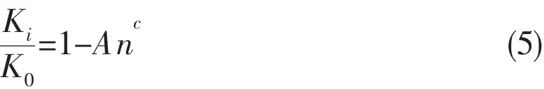
where A and C are constants.
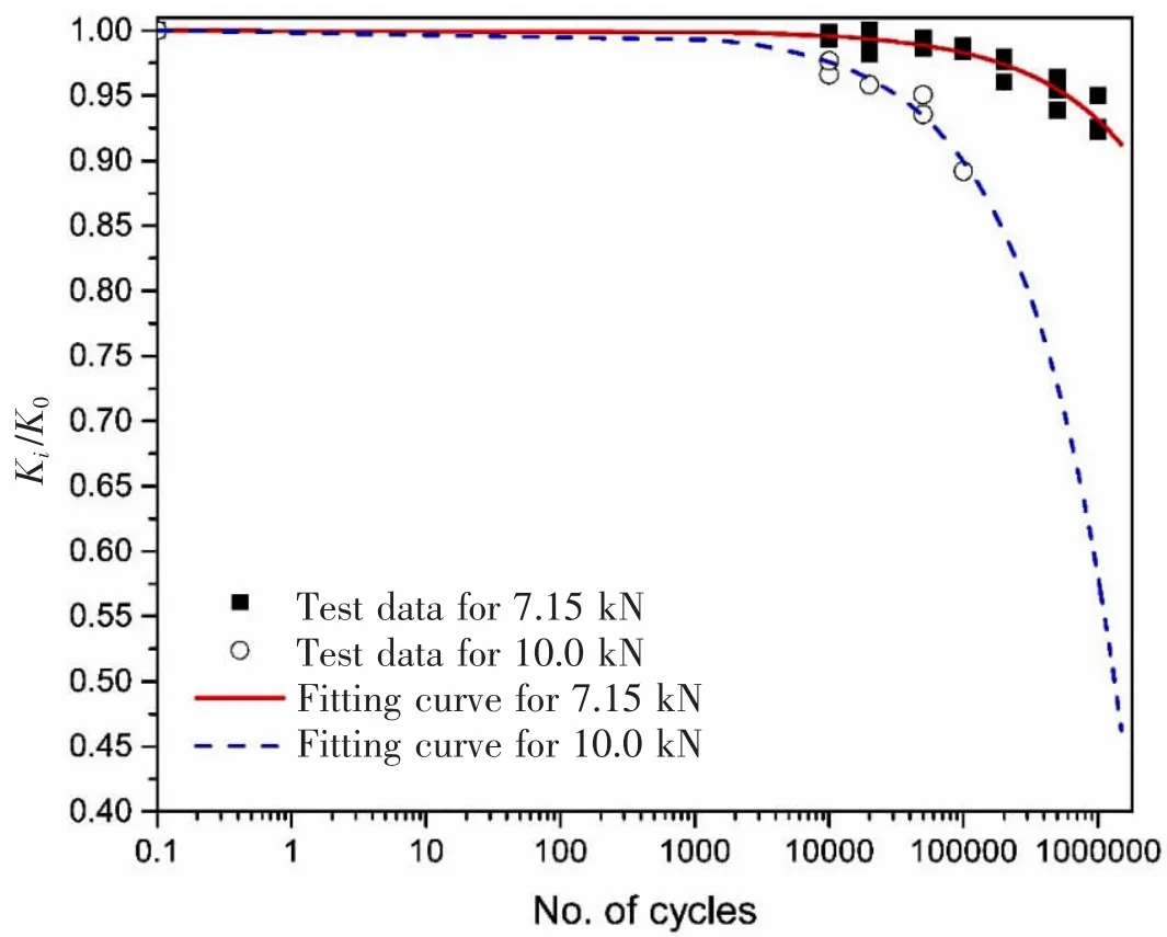
Fig.10 Stiffness degradation
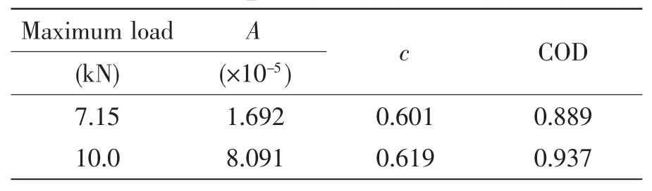
Tab.2 Fitting constants for specimens F1-F6
For specimens F1-F3 under 7.15 kN and specimens F4-F6 under 10.0 kN,fitting parameters of the function are shown in Tab.2.As can be seen from Tab.2,fitting parameters A and c of specimens F4-F6 are greater than those of specimens F1-F3,which dedicates that the rate of stiffness degradation grows with the load level.
3 Conclusions
The static and fatigue performances of sandwich L-joints under bending have been studied by experimental investigation.And the following conclusion have been drawn from this study:
(1)The load-life(S-N)curves were established for the sandwich L-joint by a sigmoid function and linear fitting.The sigmoid function is recommended for the case studied here.In order to achieve at least 1 000 000 cycles,which is the acceptable fatigue life for naval vessels,the maximum service load suggested by the sigmoid function should be limited to 9.30 kN.
(2)Stiffness degradation during fatigue life follows a power function and the rate of stiffness degradation grows with the load level.
(3)Cracks existed within the arc bracket area in both static and fatigue tests while the way crack propagated was totally different.Cracks occurred suddenly at the time of complete structural failure for specimens loaded statically.While in fatigue tests,after a certain number of cycles,crack initiated and then propagated to failure.Propagation process of crack is divided into three stages:small crack initiates where ‘stress whitening’ exists;crack propagates along the thickness direction of the arc bracket;crack covers the section of arc bracket and the whole L-joint fails.Based on observation on small blocks cut from the joints suffering fatigue failure,debonding between skins and foam core,delamination and fiber breakage are the main failure modes.
[1]Mostafa A,Shankar K,Morozov E V.Experimental,theoretical and numerical investigation of the flexural behaviour of the composite sandwich panels with PVC foam core[J].Appl Compos Mater,2014,21(4):661-675.
[2]Di Bella G,Calabrese L,Borsellino C.Mechanical characterisation of a glass/polyester sandwich structure for marine applications[J].Mater Design,2012,42:486-494.
[3]Iva?ez I,Santiuste C,Sanchez-Saez S.FEM analysis of dynamic flexural behaviour of composite sandwich beams with foam core[J].Compos Struct,2010,92(9):2285-2291.
[4]Toftegaard H,Lystrup A.Design and test of lightweight sandwich T-joint for naval ships[J].Composites Part A:Applied Science&Manufacturing,2005,36(8):1055-1065.
[5]Khalili S M R,Ghaznavi A.Numerical analysis of adhesively bonded T-joints with structural sandwiches and study of design parameters[J].Int J Adhes,2011,31(5):347-356.
[6]Han K S,Hwang W.Fatigue life prediction and failure mechanisms of composite materials[J].Adv Compos Mater,1992,2(1):29-50.
[7]Lin Y.On fatigue damage accumulation and material degradation in composite materials[J].Composites Science&Technology,1989,36(4):339-350.
[8]Kilic H,Haj-Ali R.Progressive damage and nonlinear analysis of pultruded composite structures[J].Composites Part B Engineering,2003,34(3):235-250.
[9]Kulkarni N,Mahfuz H,Jeelani S,Carlsson L A.Fatigue crack growth and life prediction of foam core sandwich composites under flexural loading[J].Compos Struct,2003,59(4):499-505.
[10]Gonabadi H I,Oila A,Bull S.Fatigue of sandwich composites in air and seawater[J].Journal of Bio-and Tribo-Corrosion,2016,2(2):1-7.
[11]Bey K,Tadjine K,Khelif R,Chemami A,Benamira M,Azari Z.Mechanical behavior of sandwich composites under three-point bending fatigue[J].Mech Compos Mater,2015,50(6):747-756.
[12]Shafiq B,Quispitupa A.Fatigue characteristics of foam core sandwich composites[J].Int.J Fatigue,2006,28(2):96-102.
[13]Abbadi A,Tixier C,Gilgert J,Azari Z.Experimental study on the fatigue behaviour of honeycomb sandwich panels with artificial defects[J].Compos Struct,2015,120:394-405.
[14]Dan Z,Burman M.Failure mode shifts during constant amplitude fatigue loading of GFRP/foam core sandwich beams[J].Int.J Fatigue,2011,33(2):217-222.
[15]Kanny K,Mahfuz H.Flexural fatigue characteristics of sandwich structures at different loading frequencies[J].Compos Struct,2005,67(4):403-410.
[16]Mathieson H,Fam A.Static and fatigue behavior of sandwich panels with GFRP skins and governed by soft-core shear failure[J].J Compos Struct,2014,18(2):785-793.
[17]Mathieson H,Fam A.High cycle fatigue under reversed bending of sandwich panels with GFRP skins and polyurethane foam core[J].Compos Struct,2014,113(16):31-39.
[18]Kulkarni N,Mahfuz H,Jeelani S,Carlsson L A.Fatigue failure mechanism and crack growth in foam core sandwich composites under flexural loading[J].Journal of Reinforced Plastics&Composites,2004,23(1):83-94.
[19]Dimitrov N,Berggreen C.Probabilistic fatigue life of balsa cored sandwich composites subjected to transverse shear[J].J Sandw Struct Mater,2015,17(5):562-577.
[20]Bahram A,Majid A,Hossien H S,Abbas J A.Experimental analysis of behavior and damage of sandwich composite materials in three-point bending.Part 2.Fatigue test results and damage mechanisms[J].Strength Mater+,2009,41(3):257-267.
[21]Manujesh B J,Rao V.Fatigue behavior and failure mechanism of PU foam core E-glass reinforced vinyl ester sandwich composites[J].International Journal of Materials Engineering,2013,3(4):66-81.
[22]Vassilopoulos A P,Georgopoulos E F,Keller T.Comparison of genetic programming with conventional methods for fatigue life modeling of FRP composite materials[J].Int.J Fatigue,2008,30(9):1634-1645.
彎曲載荷下復合材料夾芯“L”型接頭強度和疲勞試驗研究
曾海艷a,b, 嚴仁軍a,b, 徐 琳b, 桂思源b
(武漢理工大學 a.高性能船舶技術教育部重點實驗室;b.交通學院,武漢 430063)
文章研究了復合材料夾芯“L”型接頭在彎曲載荷下的靜強度和疲勞問題。通過靜加載試驗,得到該接頭的極限承載能力和破壞模式。在此基礎上,對不同載荷水平下的試件進行疲勞試驗。基于試驗數據建立S-N曲線,比較了半對數線性擬合和“S”型函數擬合結果。結果表明,“S”型曲線的預測結果好于半對數線性擬合。同時,分析了疲勞載荷下的接頭破壞模式,包括夾芯和面板之間脫粘、面板分層和纖維斷裂。根據試驗現象劃分了表明裂紋擴展的3個階段。建立了剛度退化模型表現不同載荷水平下剛度退化規(guī)律。
復合材料夾芯結構;疲勞壽命;“L”型節(jié)點;剛度退化;S-N
O342
A
曾海艷(1990-),女,武漢理工大學交通學院博士研究生;
嚴仁軍(1962-),男,武漢理工大學交通學院教授,博士生導師;
徐 琳(1979-),女,武漢理工大學交通學院講師;
桂思源(1993-),男,武漢理工大學交通學院碩士研究生。
O342 Document code:A
10.3969/j.issn.1007-7294.2017.12.009
date:2017-07-23
Supported by the National Natural Science Foundation of China(Grant No.51609185);the State Key Laboratory of Ocean Engineering in Shanghai Jiao Tong University(No.1613)
Biography:ZENG Hai-yan(1990-),female,Ph.D.student of Wuhan University of Technology,E-mail:zenghaiyan916@163.com;YAN Ren-jun(1962-),male,professor/tutor.
1007-7294(2017)12-1540-11
猜你喜歡
建材發(fā)展導向(2022年2期)2022-03-08 01:44:04
建材發(fā)展導向(2021年14期)2021-08-23 00:56:16
中國材料進展(2019年10期)2019-12-07 05:32:14
纖維復合材料(2018年3期)2018-04-25 07:22:58
電子測試(2017年11期)2017-12-15 08:57:13
山東工業(yè)技術(2016年15期)2016-12-01 05:31:34
中國塑料(2015年6期)2015-11-13 03:02:54
中國塑料(2015年11期)2015-10-14 01:14:14
中國塑料(2015年8期)2015-10-14 01:10:41
應用化工(2014年10期)2014-08-16 13:11:29

- 船舶力學的其它文章
- A New Method for Fast Estimation of Collision Dissipated Energy and Its Application in Ship-Platform Collision Accident
- Optimization of Composites Shell Subjected to Hydrostatic Pressure to Maximize Design Pressure Factor
- Fatigue Analysis for Welded Joints of Offshore Wind Turbine under Three Wind Loads
- Algorithm Simulation of Ship Dynamic Positioning Using Adaptive Fading Memory Filter
- Enhanced Extinction Curve Method for Roll Damping Estimation
- Numerical Predictions of the PPTC Propeller Tip Vortex Cavitation in Uniform Flow