鈣鋁鎂合金陰極對WOLED器件性能的影響
2015-07-04 09:27:12王璐薇張方輝
發(fā)光學(xué)報 2015年12期
王璐薇,張方輝
(陜西科技大學(xué) 電氣與信息工程學(xué)院,陜西西安 710021)
1 Introduction
Currently,the majority of materials used for the organic light emitting device belong to hole transport type,injection and transport of the holes are relatively easy by ITO and the hole transport layer[1-2].Alq3is the most commonly used electron-transporting material at present,its electron mobility is two
In order to overcome the shortcomings of the single metal cathode,the low work function metal with very active chemical character is combined with high work function metal whose chemical character is relatively stable to form the alloy cathode[5].The alloy cathode can not only improve the stability of the material in the air,but also reduce the electron injection barrier,which greatly improves the device performance.As early as 1987,Kodak first proposed a double-layer structure of OLED which significantly reduced the driving voltage by using Mg∶Ag alloy cathode,and it also reported for the first time that the alloy cathode was applied to OLED.In addition,the alloy is widely used as cathode material in the transparent and top-emitting devices,such as Yb∶Ag,Yb∶Au,Sm∶Ag alloy and so on,and results in the devices having a high transmittance[6].
In this paper,Ca∶Al∶Mg alloy was used as the cathode of the device.Through the production of different cathode structure devices and the measurement of the devices performance,Ca∶Al∶Mg alloys as cathode for optimal proportion can be derived.
2 Experiments
First,the cleanliness of the ITO glass is sent into the preparation chamber through plasma bombardment.After 10 minutes,the ITO substrate is transported to the evaporation chamber.When the evaporation chamber pressure reaches 7×10⁻⁴Pa,the organic and metal layers are evaporated onto the ITO substrate in turn.The device structures are as follows:ITO/MoO3(30 nm)/NPB(40 nm)/mCP∶Firpic(8%,40 nm)/CBP∶R-4B(2%)∶Ir(ppy)3(14%,5 nm)/TPBi(10 nm)/Alq3(40 nm)/Ca∶Al∶Mg(x%,100 nm)(x=0,5,10,15,20,25),respectively,represent the devices of A,B,C,D,E,and F.x%is the mass fraction of Mg.A is the contrast device.The mass fraction of Ca is 15%.In this structure,ITO and Ca∶Al∶Mg are used as the anode and the cathode,respectively.NPB is the hole transporting layer.Firpic is used as a dopant of blue light-emitting layer.R-4B is used as a dopant of red light-emitting layer.Ir(ppy)3is used as a dopant of green light-emitting layer.TPBi is the hole blocking layer.In addition,in order to verify the effect of Mg on the electronic injection capability of the device,two sets of electronic injection devices are made.The device structures are as follows:ITO/Alq3(40 nm)/Ca∶Al∶Mg(5%,100 nm)(Device G)and ITO/Alq3(40 nm)/Ca∶Al(100 nm)(Device H).
The materials used in the experiment are purchased from several companies except the alloy material which is formed in the laboratory.The synthesized procedure of Ca∶Al∶Mg alloy includes fusion in the quartz glass tube under vacuum and natural cooling.
The characteristics of devices are measured using a Photo Research PR-670 spectroradiometer and a Keithley source 2400.
3 Results and Discussion
Fig.1 shows the brightness-voltage characteristics of the devices.It can be seen that the brightness of the devices increases firstly and then decreases with the increasing of Mg content.The increasing brightness of device A,B,C,and D is mainly due to the lower work function of the metal cathode and the better electron injection with the increasing ofMg content,which results in the bigger recombination probability of electrons and holes.The brightness of device E and F tends to decrease.The reason is the carriers distribute unreasonable causing the light-emitting concentration quenching. The maximum brightness is 1 504 cd/m2at 12 V.
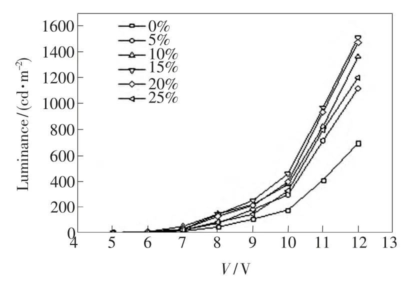
Fig.1 Luminance-voltage characteristics of device A,B,C,D,E,and F,respectively.
Fig.2 shows the current efficiency-current density characteristics of the devices.It can be seen from the figure,the trends of the six devices are identical and efficiency roll-off is relatively flat.This explains using Ca∶Al∶Mg alloy as cathode can improve the stability of the device.The current efficiency of device A,B,C,and D tends to increase and device E and F tends to decrease.Device D has the maximum current efficiency of 14.3 cd/A at 6.9 mA/cm2.The main reason of the high efficiency is that the lower work function of the metal and the stronger electron injection capacity result in the electron and hole injection into balance for this device.For device E,the work function of the cathode is the lowest,but the efficiency is falling.This is because the electrons inject too much,and a part of the electrons and holes can not recombine and release out in other forms[7].
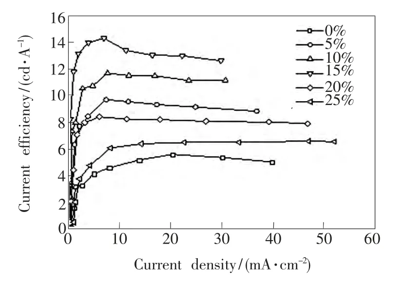
Fig.2 Current efficiency-current density characteristics of device A,B,C,D,E,and F,respectively.
Fig.3 shows the current density-voltage characteristics of the devices.It can be seen from the figure,the trends of the six devices are similar,that is,the current density of the devices increases along with the voltage.The current density of the devices increases slowly along with the voltage at low voltage,while current density increases rapidly beyond a certain voltage.For device A,B,C,and D,the curves change little,the current density is smaller.The current density of device D is the smallest.The reason is that the electron injection can completely meet the hole carriers in the light emitting layer and the electrons and holes form an effective recombination luminescence,which results in a decrease in current density and a significant increase in efficiency.For device E and F,the curves show a clear change and tend to increase.At the same voltage,the current density of device F is larger than other devices.
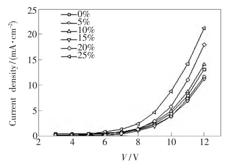
Fig.3 Current density-voltage characteristics of device A,B,C,D,E,and F,respectively.
Fig.4 shows the curve of current density-voltage of device G and H.It can be seen that the current density of device Gis higher than that of device H at the same voltage.The current density of device G is enhanced 6.1 times as compared to that of device H at 8 V driven voltage.This shows that the introduction of Mg can effectively improve the injection of electrons from the cathode to the organic layer.
Fig.5 shows EL spectra at 10 V driving voltage of the devices.It can be seen that EL spectra of the devices completely cover the total visible region ranging from 380 to 780 nm.The spectra insist of threeprimary peaks at 468,512,and 556 nm.The peak at 468 nm is the characteristic luminescence of Firpic.The luminous peak of Ir(ppy)3is located at 512 nm.The luminous peak of R-4B is located at 604 nm.The peak intensities of device B,C,D,and E differ bigger.The intensity of red emission is large,followed by the green emission,and the blue emission is weak.The intensity of red emission of device D is the largest.The RGB spectra of device A and F are relatively balanced.

Fig.4 Current density-voltage characteristics of device G and H
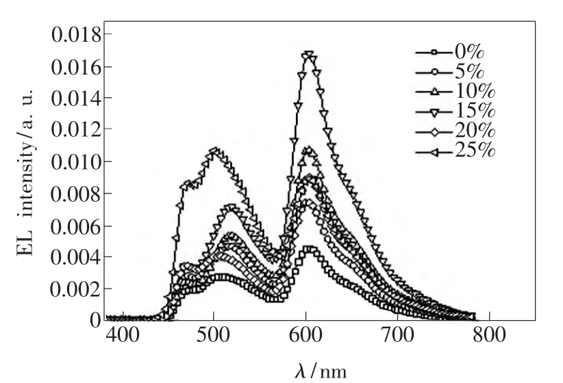
Fig.5 EL spectra of device A,B,C,D,E,and F at 10 V,respectively.
Fig.6 shows the normalized EL spectra of device D at different driving voltage.It can be seen that the luminous peak of red has no bias shift,but the luminous peak of blue and green gets a slight deviation at different driven voltage.The intensity of red emission is similar,but the intensities of blue and green emission tend to increase with the increasing of driving voltage.The reason is probably due to the R-4B doping concentration of 2%is small.With the increasing of voltage,the number of carriers reaches the peak and the light reaches saturation.The doping concentrations of Firpic and Ir(ppy)3are 8%and 14%respectively,and the proportions of the two dopants are respectively large.More highenergy excitons are formed on Firpic and Ir(ppy)3with the increasing of voltage,which results in the increasing of the recombination probability of electrons and holes.Therefore,the number of carriers has not reached its peak and has been increasing.
Table 1 shows the color coordinate of device D at different voltage.It can be seen that the color coordinates are almost no change with the increasing of the bias voltage.The stability of color coordinate is better.The chroma is largely insensitive to the driven voltage.When the voltage ranges from 6 to 9 V,the color coordinates are(0.460 6,0.427 9),(0.461 1,0.428 3),(0.462 0,0.428 8),and(0.462 8,0.429 1),respectively.At different voltage,device D can emit white light which belongs to warm yellow color[8].
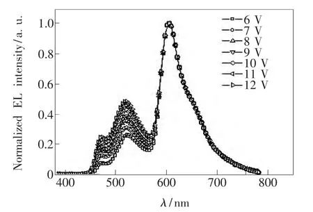
Fig.6 Normalized EL spectra of device Dat different driving voltage
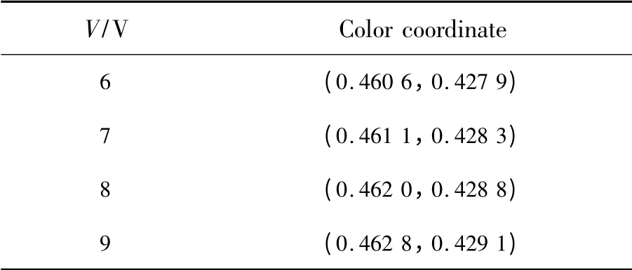
Table 1 Voltage-color coordinate of device D
4 Conclusion
Based on the red and green/blue light emitting layer,six white phosphorescent OLEDs are made by using Ca/Al/Mg alloy as cathode,and the effects of different proportion of Ca/Al/Mg alloy on OLEDs are researched by changing the doping ratio of Mg.Theexperiment results show that Ca/Al/Mg alloy cathode can not only improve the brightness and efficiency of the device,but also improve the stability.When the mass fraction of Mg is 15%,the device has the best performance:The maximum brightness is 1 504 cd/m2,the maximum current efficiency is 14.3 cd/A at 6.9 mA/cm2,and the emitting white light belongs to warm yellow color at different driving voltage.
[1]Ling D G.Effect of Coupled Structures Cathode and Thin Organic Layer on The Performance of OLED[D].Beijing:Beijing Jiaotong University,2009(in Chinese).
[2]Wu J.The Model of Carriers'Transport and Recombination in OLED and A Study on Phosphorescent Dye Doped OLED[D].Jinan:University of Jinan,2007(in Chinese).
[3]Zhao F C.Luminescence Characteristics of OLED with Phosphor-doped Host-quest Structure[D].Baoding:Hebei University,2009(in Chinese).
[4]Lai SL,Chan M Y,Lee CS,et al.Investigation of calcium as high performance cathode in small-molecule based organic light-emitting devices[J].Appl.Phys.,2003,94:7297-7299.
[5]Liu Q.Research on electron Injection Materials for Organic Light-emitting Diodes and The Related Mechanisms[D].Beijing:Tsinghua University,2009(in Chinese).
[6]Kim SH,Yoon JH,Jang J,et al.Effect of calcium interlayer thickness on electron injection of lithium quinolate/Ca/Al cathodes[J].Appl.Surf.Sci.,2008,254(21):7061-7063.
[7]Xie K.Research on Cathodes for Organic Light-emitting Diodes and The Related Mechanism[D].Beijing:Tsinghua University,2012(in Chinese).
[8]Chen J M,Chen J D,Wu Z F.White OLED Lighting[M].Shanghai:Shanghai Jiao Tong University Press,2011(in Chinese).