Generating multi-layer nested chaotic attractor and its FPGA implementation?
2021-06-26 03:03:34XuenanPeng彭雪楠YichengZeng曾以成MengjiaoWang王夢蛟andZhijunLi李志軍
Chinese Physics B 2021年6期
Xuenan Peng(彭雪楠) Yicheng Zeng(曾以成) Mengjiao Wang(王夢蛟) and Zhijun Li(李志軍)
1School of Physics and Optoelectronic Engineering,Xiangtan University,Xiangtan 411105,China
2School of Automation and Electronic Information,Xiangtan University,Xiangtan 411105,China
Keywords: multi-layer nested attractors,composited attractors,multi-scroll attractors,FPGA realization
1. Introduction
Chaos phenomenon is widespread existences in nature.On the one hand, chaos phenomenon is undesirable in some fields like construction engineering, because any tiny disturbance may result in fatal disaster. On the other hand,researchers need more complex chaotic consequences to achieve practical applications,such as chaos-based encryption schemes.[1,2]The multi-scroll chaotic attractor is considered as a manifestation of the system having complex dynamic behaviors. Obtaining multi-scroll chaotic systems can be summarized as the following two parts.
One is to design novel chaotic systems and modifying an existing chaotic system.[3–5]A four-dimensional(4D)smooth quadratic autonomous system, constructed by a linear controller to a three-dimensional (3D) pseudo four-wing system,was proposed.[6]A 4D cyclic symmetry chaotic system with multi-stability and coexisting attractors was designed.[7]The 4D systems have vast key spaces, but need more resources to implement them. Thus, lower dimensional chaotic systems with complex behaviors have been widely researching in recent years.[8,9]A 3D chaotic system with trigonometric function as a nonlinear controller for generating hidden and self-excited attractor was proposed.[10]Fractional-order chaotic systems are extremely useful to describe many realworld phenomena.[11]A 3D fractional-order chaotic system generating one to four wing controllable chaotic attractor was reported.[12]A fractional order dynamical system with a variable double-scroll attractor on a line, lattice, and 3D grid was introduced.[13]However, it is difficult to reconstruct a novel chaotic system with more complex dynamical behaviors. Moreover,these systems only generate chaotic attractors with a limited number of scrolls.
Another method is introducing nonlinear functions into chaotic models to obtain multi-scroll attractors.[14–17]The hyperbolic tangent function series was designed for generating multi-scroll attractor.[18]By using offset boosting technique and introducing absolute-value function, the number of coexisting attractors in the chaotic system can be doubled.[19]A Chua’s diode with multi-segment piecewise linearity was designed for generating multi-scroll Chua’s attractors.[20]Recently, a technique based on non-autonomous functions for generating multi-scroll attractors was proposed.[21]Multidouble-scroll attractors were generated by adding multi-levellogic pulse excitation in double-wing chaotic systems.[22]By using non-autonomous approaches,the modified Sprott C system creating multi-scroll hidden attractors was reported.[23]Sigmoid function was used to control system generating multiscroll hidden chaotic attractor.[24]Obtaining various types multi-scroll attractors was extensively researched, but the methods for increasing the number of nested chaotic attractors have not been reported.
In this paper, we introduce a non-autonomous approach to create multi-layer nested attractor in modified Chua’s system. The PW function plays a critical role in non-autonomous approaches. Most works only use one PW function to control chaotic system. But, due to modified Chua’s system having second power and third power nonlinear terms,we need to design ‘staircase function’ and ‘quadratic staircase function’ to control the system. Then, the steps for creating multi-layer nested attractor are elaborated. Great majority nested attractor merely has one layer, while our method can create threelayer even multi-layer nested attractor. Meanwhile, the novel chaotic oscillator is coded in FPGA chip by employing Verilog HDL.As compared with original system,we can obtain more complex chaotic sequences with little increased consumption of resources. The rest part of this paper are organized as follows:in Section 2,the quadratic staircase function is designed.A chaotic model is proposed and analyzed in Section 3. The FPGA realization of these chaotic models is displayed in Section 4. Finally,some conclusions are included in the last section.
2. Quadratic staircase function
The pulse signalfi(t)is expressed as follows:
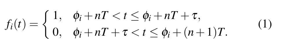
where,Tis period,τis pulse-width,andφiis start time. The duty ratio is defined as 0.5. And the quadratic staircase functionQ(t) is the summation of squares ofNpulse signalfi(t)and is written as follows:
According to the above equation, the level-logic ofQ(t) is(N+1)2,N2,(N ?1)2,...,22,1. The time series of the above functions are plotted in Fig.1.

Fig.1. Time series of nonlinear functions. (a)Pulse signal with different start time(T =40,φ1=0,φ2=τ/2). (b)Quadratic staircase function got by(f1(t)+f2(t))2.
3. Multi-layer nested chaotic attractor
3.1. Chaotic model
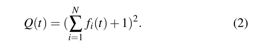
In this section, by introducing PW function to modified Chua’s system with nested attractor,multi-layer nested chaotic system is constructed. Firstly,the modified Chua’s system has eight terms including three nonlinear terms.[4]The equations are expressed as follows:
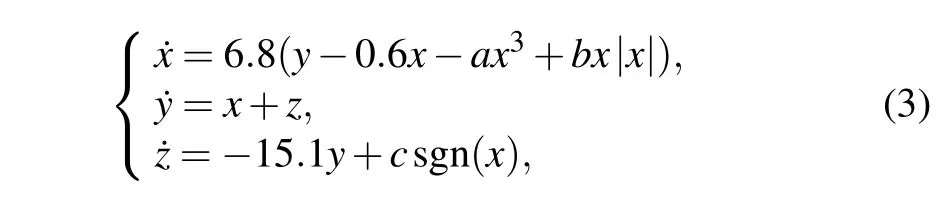
wherex,y,andzare state variables and parametersa,b,andcare constants. The parameters are set toa=0.45,b=1.1 andc=1 in Ref.[4]. Here,we concisely exhibit the dynamics of this system. The Lyapunov exponents’spectrums and bifurcation diagramsversusparametersaandbare shown in Fig.2.Dynamics of system(3)exhibited by spectrum are almost the same as bifurcation diagram displaying. Whena >0.5 orb <1.1, chaotic mapping area of system (3) decreases gradually.
Fig. 2. (a) Lyapunov exponents’ spectrum versus parameter a (b = 1.1,c=1). (b) Lyapunov exponents’ spectrum versus parameter b (a=1.1,c=1). (c) Bifurcation diagram varying with parameter a. (d) Bifurcation diagram varying with parameter b.
Then,considering following transformation:by substituting?zintoz,the correspond ˙zwill change to?˙z. Transforming different state variables will result in system generating attractor symmetric about different planes. For ease to observe the results,we merely choose state variablez.The transformed system(3)is written as follows:

The novel system (4) can create chaotic attractors which is mirror symmetric with original one. The mirror symmetric attractor generated by system (4) (colored in red) and original attractor created by system(3)(colored in blue)are shown in Fig.3(a). Through this converting,a pair of symmetric attractors, which are also called two-layer attractor with one-layer nested attractor, are created. For any systems with nested attractors, changing their state variables, can create one-layer nested attractors in phase portrait.
For generating multi-layer nested attractor, we consider the following transformation:x=eX,y=eY,z=eZ(eis a real constant). The system(3)will transform to
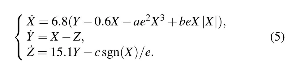
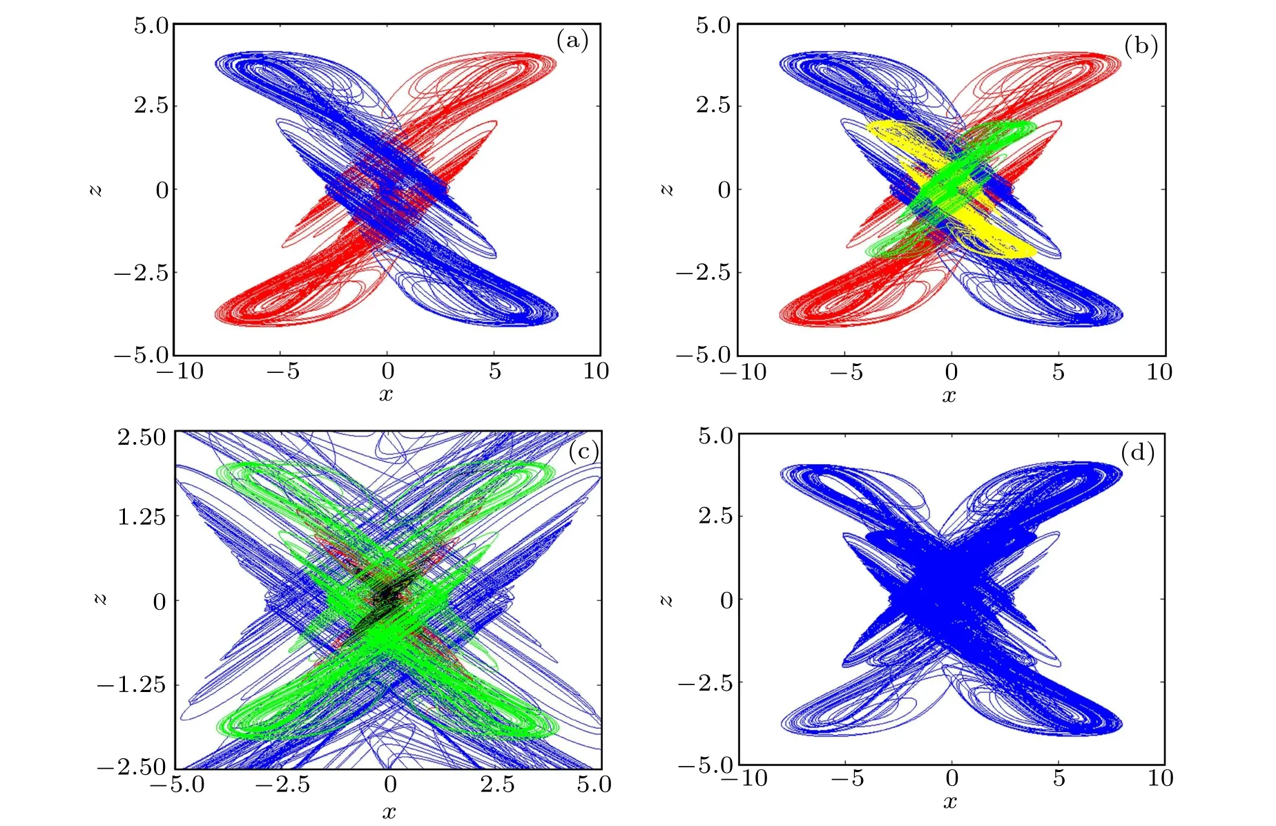
Fig. 3. (a) Mirror symmetry attractors (a=0.1125, b=0.55, c=2). (b) Mirror symmetry attractors and different amplitude attractors (compressed original attractor colored in yellow,compressed mirror image attractor colored in green). (c)Partial enlarged view of multi-layer nested attractor(first layer colored in blue,second layer colored in green,third layer colored in red,the last layer colored in black). (d)Multi-layer nested Chua’s attractor under initial condition(x0=0.1,y0=0.3,z0=0.2).
We note that the coefficient of cubic term ise2,while quadratic term iseand symbolic function term is 1/e.Through adjusting the value of parametere,the system(3)can generate different amplitude attractors as plotted in Fig. 3(b). There are fourlayer chaotic attractors generated by the above system with different parametere,which contain three-layer nested attractors. For different systems, the position and the number of parameteremay be different. In Fig.3(c),the order of attractors from outside to inside is: four normal size outside scrolls(e=1),four small size outside scrolls(e=2),four normal size inner scrolls(e=1),and four small size inner scrolls(e=2).
In the following work, we use non-autonomous method to combine these attractors for generating multi-layer nested attractors. Introducing three different types of PW function to system(3),we can get novel equations as expressed below:

where,P(t)is pulse function proposed by Honget al.[20]It is expressed as sgn(sin(0.005t)).P(t)is used to control system creating mirror symmetric attractors.Q(t) andf(t) control the amplitude of attractors generated by the system. Whena=0.1125,b=0.55,c=2,TQ=Tf=600, the multi-layer attractors generated by system(6)are shown in Fig.3(d).
The method to generate multi-layer nested attractors can be summarized as follows:(i)chaotic system having nested attractors;(ii)through changing sign of arbitrary state variables to create mirror symmetry attractors; (iii) shrinking the amplitude of attractors by compression state variables;(iv)using pulse signal to control chaotic system for combining the above attractors.
3.2. Dynamics analysis of system with multi-layer nested attractor
By setting the left-hand side of the chaotic system (6)to zero, twenty-five equilibrium points exist:S0(0, 0, 0),S1?4(?0.578e,?0.066e,±0.578e),S5?8(0.578e, 0.066e,±0.578e),S9?12(?1.718e,?0.066e,±1.718e),S13?16(1.718e,0.066e,±1.718e),S17?20(0.148e,0.066e,±0.148e),andS21?24(?0.148e,?0.066e,±0.148e),where the value of parametereis 1 or 2. The distribution of equilibrium point projection onx–zplane is shown in Fig. 4(a). The Jacobian matrix of the linearized system(6)is expressed as follows:
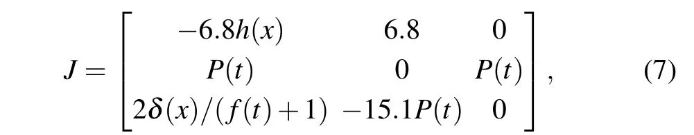
whereh(x)is written as 0.6?3aQ(t)x2+b(f(t)+1)β(x). By solving characteristic equation of the matrixJ,the eigenvalues of the equilibrium point are tabulated in Table 1.E0andE9?24are unstable index-2 saddle-focus points having one negative real root and two complex conjugate roots with positive real part;E1?8are unstable index-1 saddle points with two negative real root and a positive real root. The Lyapunov exponents’ spectrum is plotted in Fig. 4(b). Obviously, the Lyapunov exponents have hardly changed. This means that our method only changes the phase space orbits of the attractor,not the chaotic state.
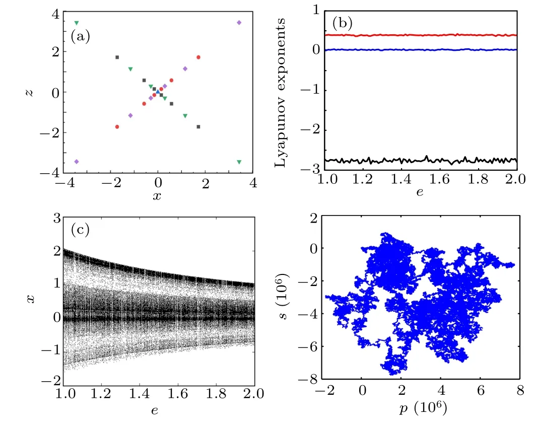
Fig.4.Distribution of equilibrium points(original attractor colored in green,mirror symmetry attractor colored in purple, compressed original attractor colored in black,compressed mirror symmetry attractor colored in red). (b)Lyapunov exponents’ spectrum varying with parameter e. (c) Bifurcation diagram varying with parameter e. (d)0–1 test of the system.
For further analyses of the chaoticity of the system (6),the bifurcation diagram and the 0–1 test are shown in Figs.4(c)and 4(d).Similar to the above conclusions,the bifurcation diagram exhibits the amplitude of the chaotic attractor decreasing.And the system(6)exhibits the irregular Brownian motion in thep–splane when(x0,y0,z0)=(0.1,0.3,0.2). Thus,the system is of the chaoticity in this condition. Moreover, the axis scales of the figure are bigger than other systems,it means the system has better randomness. According to the Table 1 and Fig.4,the sign transformation of the state variable and the proportional compression have not affected the chaoticity of the system.
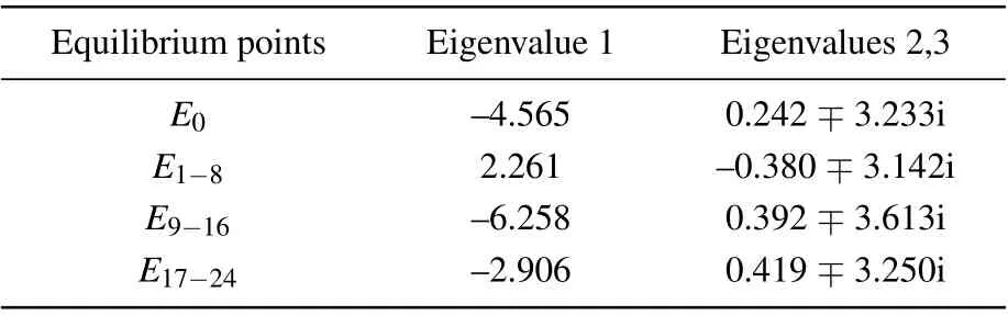
Table 1. Eigenvalues of equilibrium point.
4. FPGA realization
Digital circuits realization of the chaotic system has been researched in recent years. Recently, various 2D sine chaotic maps were realized by using microcontroller MSP430F249.[25,26]Similarly, chaos-based secure communication system employing microcontroller was designed.[27]However,as compared with microcontroller,FPGA has more benefit such as parallel calculation, easy to use numerous IP cores, and so on. Thus, FPGA-based chaotic oscillator attracted widely interest.[28–31]In this section, we employ Runge–Kutta(RK-4)numerical method and fixed-point number(1-bit signal part,7-bit integer part,24-bit decimal part)to implement system(6).
4.1. Verilog HDL encoding
State machine method is a common method to realize chaotic system in Verilog HDL programming.[32]The state machine to implement modified Chua’s system include eleven states:S0–S10. Where,S0–S6: calculate the iterate results;S7–S8: implementing RK-4 numerical method;S9: adding a positive offset into results generated byS8;S10: truncating 32-bit outputs to 14-bit for adapting DAC input. Implementation of the novel chaotic system needs extra two states:SE1,SE2.SE1:According to the logic level of PW functionP(t),selecting the chaotic model for iterating in system (3) or system (4) (logic’0’ denoting system (3), logic ’1’ denoting system (4)).SE2:according to the logic level of staircase functions to determine the value of parametere.There are two values of 1-bit register:0 and 1. Modified Chua’s oscillator module can perceive these values and make different operations. For example,when register outputting value 1, the equation 4ax3is calculated in the module, otherwise the expression isax3. Therefore, the quadratic staircase function is not directly implemented in this method. The state machine flowchart is shown in Fig.5(a).
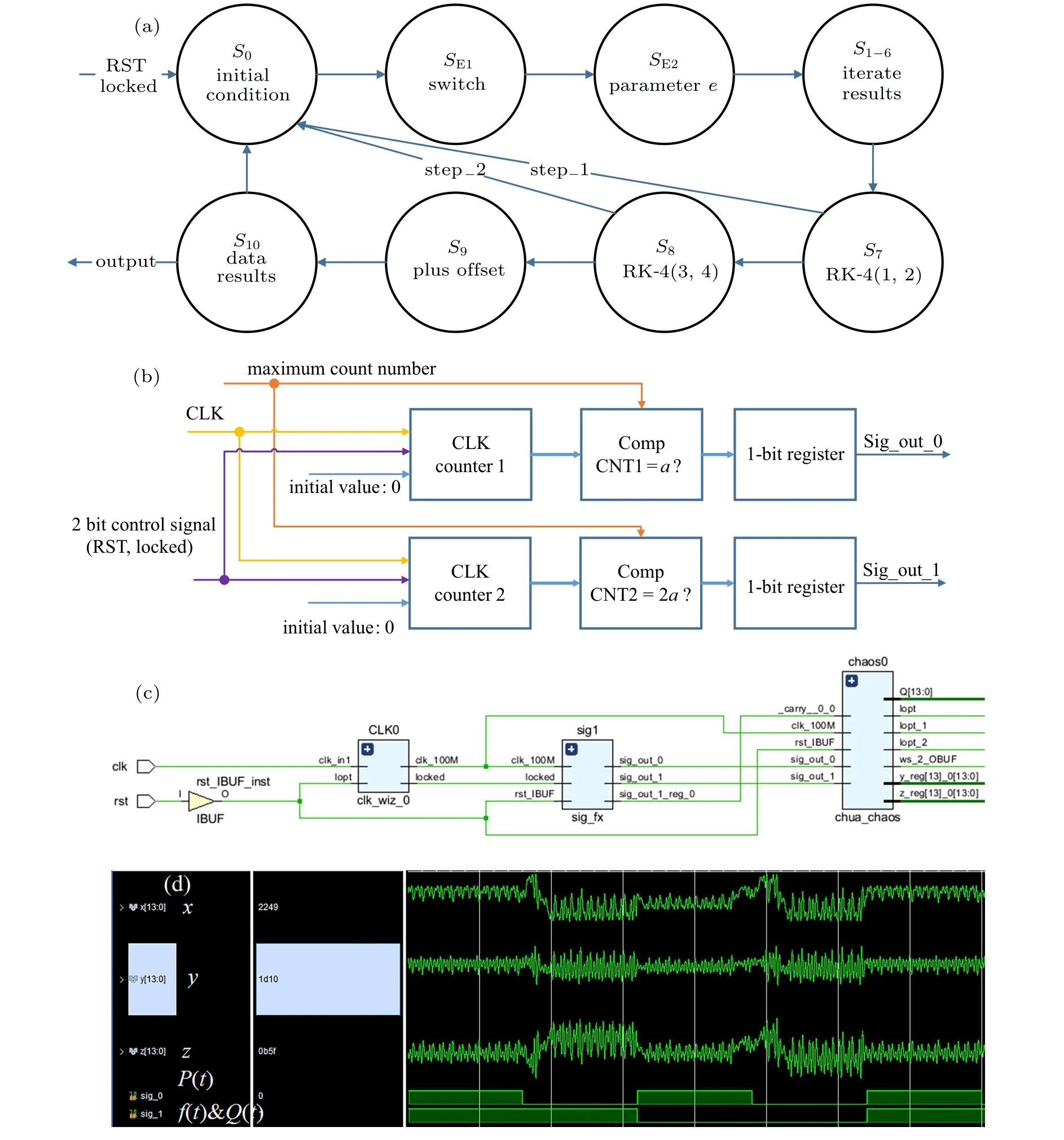
Fig.5. (a)State machine flowchart. (b)Diagram of the PW function generator,(c)RTL diagram of the top-level module. (d)Vivado timing simulation.
The digital realization of the PW functions is presented in Fig. 5(b). Where, the generator is controlled by 2-bit signal consisting of‘RST’signal and‘Locked’signal. Two clock counters are used to count high level logic of the ‘CLK’ signal. When the value of a counter is equal to maximum count value, the logic level of 1-bit register, which corresponds to this clock counter,will be inverted.
The RTL diagram of top-level module is displayed in Fig.5(c). Chaotic oscillator contains three submodules:Phase Locking Loop (PLL) module, PW function generator, and modified Chua’s oscillator. In staircase function generator,the output ’sig?out?0’ is used to transmission of theP(t) function, and another output namely’sig?out?1’is used to transmission off(t) andQ(t) functions. Modified Chua’s system contains seven output ports: three 14-bit chaotic sequences namely ‘x’, ‘y’, and ‘z’ and four 1-bit DAC driver signals namely ‘daclk?1’, ‘daclk?2’, ‘ws?1’, and ‘ws?2’. Timing analysis is shown in Fig.5(d).
4.2. Experimental results
Then, the Verilog HDL codes are synthesized and implemented by employing Xc7z020clg200 FPGA chip and AN9767 DAC chip. The resources utilization of FPGA chip is listed in Table 2(The original system in Ref.[4]is not used FPGA to realize.In order to facilitate comparison,the original system uses the same method to realize in this work).As compared to original system,realization multi-layer nested system merely increases litter resource utilization and power consuming. Digital outputs of FPGA chip are converted to analog signals by 14-bit DAC.And the experimental results are visualized by oscilloscope which are shown in Figs.6(a)and 6(b).
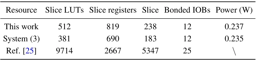
Table 2. Recourse realization.

Fig. 6. (a) Mirror symmetry Chua attractor. (b) Multi-layer nested Chua’s attractor.
5. Conclusion
A method to create multi-layer nested attractor is presented. Take modified Chua’s system as an example, the method can be summarized in three steps. First,transforming state variableszto?zfor generating mirror symmetric attractors. Second, compressing state variablesetimes for obtaining small-amplitude attractors. Finally,introducing PW functions into system for combining above phenomena. Through employing this non-autonomous method,the modified Chua’s system can create three-layer nested attractors,which have not been proposed in former works. And this method does not greatly affect the chaotic state of the system. Moreover, the approach can be applied in other chaotic systems with nested attractors. Then,the oscillator is implemented by using Xilinx Xc7z020clg200 FPGA chip. Resource consuming of novel oscillator is a little higher than the original modified Chua’s system. The experimental results got by oscilloscope are the same as MATLAB simulation results,which is helpful for further real-world applications.

- Chinese Physics B的其它文章
- Coarse-grained simulations on interactions between spectrins and phase-separated lipid bilayers?
- Constraints on the kinetic energy of type-Ic supernova explosion from young PSR J1906+0746 in a double neutron star candidate?
- Computational model investigating the effect of magnetic field on neural–astrocyte microcircuit?
- Gas sensor using gold doped copper oxide nanostructured thin films as modified cladding fiber
- Exact explicit solitary wave and periodic wave solutions and their dynamical behaviors for the Schamel–Korteweg–de Vries equation?
- Suppression of ferroresonance using passive memristor emulator