High precision attitude dynamic tracking control of a moving space target
2019-12-19 02:03:34YunhuWUMohongZHENGWeiHEFengWANGZhimingCHENBingHUA
CHINESE JOURNAL OF AERONAUTICS 2019年10期
Yunhu WU, Mohong ZHENG, Wei HE, Feng WANG, Zhiming CHEN,Bing HUA
a Micro-Satellite Research Center, Nanjing University of Aeronautics and Astronautics, Nanjing 210016, China
b Shanghai Electro-Mechanical Engineering Institute, Shanghai 201109, China
c Research Center of Satellite Technology, Harbin Institute of Technology, Harbin 150001, China
KEYWORDS
Space moving target;
Attitude dynamic tracking;
Backstepping controller;
Improved virtual control input;
Hybrid actuator
Abstract On-orbit spacecraft face many threats,such as collisions with debris or other spacecraft.Therefore,perception of the surrounding space environment is vitally important for on-orbit spacecraft. Spacecraft require a dynamic attitude tracking ability with high precision for such missions.This paper aims to address the above problem using an improved backstepping controller. The tracking mission is divided into two phases:coarse alignment and fine alignment.In the first phase,a traditional saturation controller is utilized to limit the maximum attitude angular velocity according to the actuator’s ability. For the second phase, the proposed backstepping controller with different virtual control inputs is applied to track the moving target. To fulfill the high precision attitude tracking requirements, a hybrid attitude control actuator consisting of a Control Moment Gyro(CMG)and Reaction Wheel(RW)is constructed,which can simultaneously avoid the CMG singularity and RW saturation through the use of an angular momentum optimal management strategy, such as null motion. Finally, five simulation scenarios were carried out to demonstrate the effectiveness of the proposed control strategy and hybrid actuator.
1. Introduction
The number of on-orbit spacecraft has increased rapidly with increasingly frequent human activity in space.1The demands for space debris and failed spacecraft surveillance are becoming increasingly urgent. According to a 2015 report from the US National Aeronautics and Space Administration (NASA),there are more than 13000 pieces of objects floating in earthsynchronous orbit, which has increased by 20% over the past five years2-3. That debris and a large number of spacecraft pose a great risk to other spacecraft, resulting in losses of millions of dollars.For example,the American Iridium 33 satellite collided with Russian Cosmos 2251 satellite on February, 10,2009, and generated more than 280 new pieces of debris.4
Traditional observation tasks are carried out by ground stations.5However, due to limitations of ground station distributions and ground telescope apertures, it is difficult to achieve ideal results from ground-based observations.Therefore, it is preferable to perform these tasks using a space-based system from a close distance to achieve higher resolutions.6For example, the American space-based infrared system and Soviet Union’s Oko emerged at a historic moment.7The attitude tracking control problem of spacebased observational tasks has become the key research area for the United States, the European Union, China and other space powers.
The missions mentioned above have placed higher requirements on attitude control subsystems. On one hand, rapid rotational maneuverability of approximately 5(°)/s or more is required,such as that for the Pleiades high-resolution imaging satellite.8On the other hand, it is necessary to track dynamic moving targets to obtain high-resolution images with high precision, such as for XSS-10.7Unlike for a rest-to-rest attitude maneuver, the spacecraft boresight is commanded to track the ground or space target incessantly.
Up to now,different models and control architectures have been discussed in references to resolve these problems, including Proportion Derivative (PD), Proportion Integral Derivative (PID), fuzzy control, sliding-mode control and backstepping control. Lu and Xia9studied the topic of finitetime attitude tracking for rigid spacecraft using a fast nonsingular terminal sliding mode controller.Wu et al.10presented a backstepping controller for a space moving target tracking.Kristiansen11studied another backstepping attitude tracking controller for high precision pointing for a ground target or other satellite tracking for transmitting data. However, how to choose the virtual control input and generate large and precise control torques were not covered.
There is no denying that a satellite’s attitude tracking mode can only be guaranteed by using particular actuators with large and high precision outputs. Therefore, hybrid actuators have been taken into consideration in many research studies. For example, the combination of a Reaction Wheel (RW) and thruster was studied by Ye et al.12but the thruster may pollute optical instruments.13In another example, a combination of a Control Moment Gyro(CMG) and RW was suggested.14-16In this paper, a hybrid actuator system consisting of 4 CMGs and 3 RWs will be adopted to afford the required large torque. The CMG singularity and RW saturation will be avoided simultaneously through the cooperation between the two actuators.
This paper aims to present an improved backstepping controller for a high precision attitude dynamic tracking mission of a space moving target with two virtual control inputs. The remainder of this work is outlined as follows.Section 2 briefly presents the attitude kinematics and dynamics. The space moving target tracking mission is then described in Section 3. The backstepping attitude tracking controller design follows in Section 4. The hybrid actuator configuration and null motion steering strategy are constructed in Section 5. Numerical simulations are reported in Section 6 to demonstrate the efficiency of the proposed control method as well as the strategy. Finally, Section 7 concludes the entire work of this research.
2. Attitude kinematics and dynamics
2.1. Coordinate frames
In this paper, three right-handed coordinate frames—an Inertial Frame, Orbit Reference Frame and Spacecraft Body Frame-are used and are now defined.
Inertial Frame OXIYIZI: Its origin is located at the center of mass of the Earth. The OXIaxis points to the equinox,and the OZIaxis is along the Earth’s rotation axis.
Orbit Reference Frame OXOYOZO: Its origin is located at the center of mass of the spacecraft. The OYOaxis is along the anti-symmetric direction of the orbit momentum, and the OZOaxis points to the Earth’s center.
Spacecraft Body Frame OXBYBZB: Its origin is located at the center of mass of the spacecraft, and the three axes of the frame coincide with the three major axes of the spacecraft.
2.2. Quaternion kinematic
The spacecraft attitude kinematic model is represented by the quaternion Q=[q0,qT]T, where q0is the scalar part, and q=[q1,q2,q3]Tis the vector part,

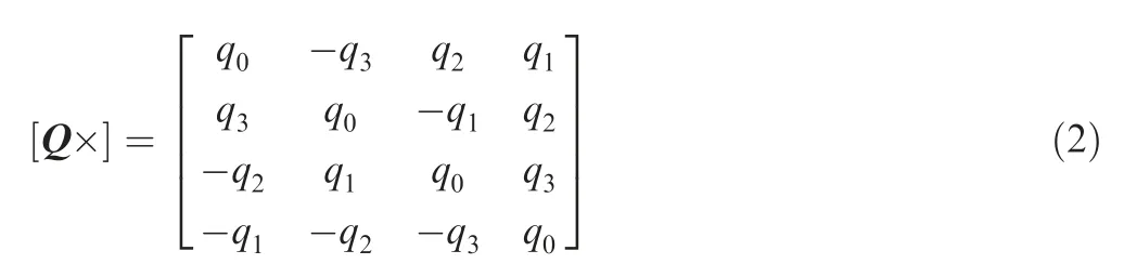
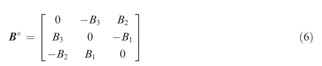
where ω=[ωx,ωy,ωz]Tis the attitude angular velocity, and the matrix [Q×] has the form,

Obviously, we have,
where E3∈R3×3denotes an identity matrix. For any vector,we have,
2.3. Attitude dynamic
The momentum of the whole spacecraft is taken as H=Jω+h, in which J is the moment of inertia of the spacecraft,and h is the momentum of the attitude control actuator.The dynamic model of the spacecraft can be written as,
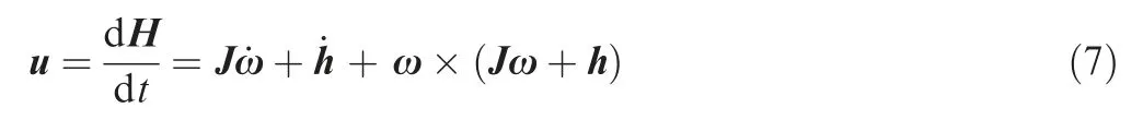
where u is the sum of total disturbance torque and control torque.
The time differential of Eq. (4) becomes,

3. Space moving target tracking mission description
The space moving target tracking task has two work modes,which are attitude adjustment and holding and target observation, as shown in Fig. 1. The attitude adjustment and holding phase from A to B is also known as the coarse alignment phase, during which the spacecraft is preparing for the target observation.Because it is the coarse alignment phase,the accuracy requirement is not very strict.In the fine alignment phase,the spacecraft is maneuvered to track the target for observations with high dynamic accuracy less than 0.1° from B to C.Node C is the end of the tracking mission, and the spacecraft returns to the original imaging mode,for example Earth imaging,which lasts from C to D.The two phases mentioned above require rapid rotational maneuverability. For example, the attitude angular velocity should approach a peak value of approximately 3-5(°)/s in the fine alignment phase. However,that value would reach more than 10(°)/s if the attitude controller is not designed properly for the coarse alignment phase,which exceeds the capability of the actuator. The attitude angular velocity and acceleration can be restricted according to the time of the attitude adjustment process.
4. Backstepping attitude tracking controller
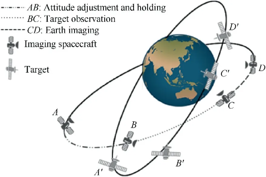
Fig. 1 Scenario for space moving target tracking.
The attitude tracking process can be divided into a coarse alignment phase and fine alignment phase. The spacecraft requires rapid rotational maneuverability in the coarse alignment phase. Due to the limitation of the actuator capability,the attitude angular velocity and acceleration should be restricted, and a traditional saturation control method17is introduced as a solution. For the fine alignment phase, however, the tracking spacecraft should keep its camera boresight pointed to the target with high precision.The target attitude is changing rapidly due to the nature of the orbital properties of the two spacecraft. Therefore, the tracking spacecraft should be capable of precise tracking and providing large and precise attitude control torque outputs. This section will focus on the controller and actuator design.
4.1. Controller design
According to the mission requirements during the fine alignment phase,the backstepping control technology is a recursive procedure,18which starts from the lowest order differential equation and selects the virtual control input step by step.Finally, the control torque u can be designed.
Step 1. Choose the backstepping states
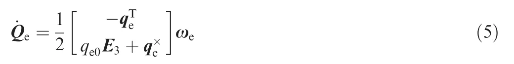
Like the rest-to-rest attitude control,the control target is to achieve Qe→[1, 0, 0, 0]Tand ωe→[0, 0, 0]T. Thereupon,we set,
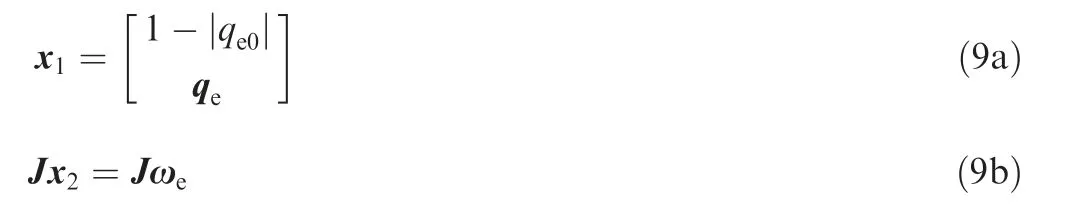
where x1and x2are the backstepping states. When Qe→[1, 0, 0, 0]Tand ωe→[0, 0, 0]T, we have x1→[0, 0, 0, 0]Tand x2→[0, 0, 0]T. The equilibrium point should be (x1, x2)=(0, 0).
The above state equations can then be written as,
Obviously, x1is not differentiable when qe0=0.To handle crossings of qe0=0, we define sgn qe0( )|qe0=0=1.
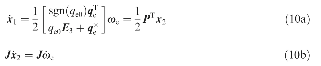
According to the nonlinear backstepping design method,to choose the equilibrium point as (x1, x2)=(0, 0), x2can be regarded as the input of x1, and the virtual control input is selected by f(x1), ensuring x2=f(x1). The extended state is x=[x1, x2, x3]T, in which x3=x2-f(x1), and Eqs. (10)therefore becomes,
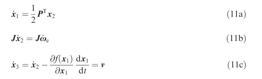
where v can be regarded as the input of x3.
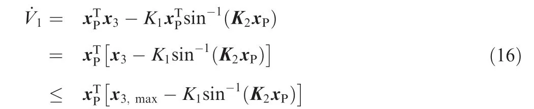
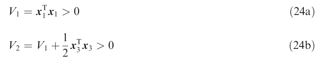
Step 2. The first candidate Lyapunov function design
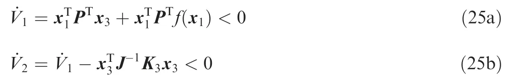
The first candidate Lyapunov function can now be chosen as,

where V1>0.Substituting Eqs.(11),the time derivative of V1is,

Obviously, f(x1) should meet the following requirements:When x1=0, we should have f(x1)=0 to finally achieve the objective of ωe→0.
Therefore, f(x1) can be chosen as,

Substituting Eq. (14) into Eq. (13) andcan be rewritten as,
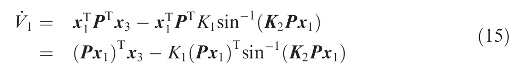
Step 3. The second candidate Lyapunov function design The second candidate Lyapunov function can now be chosen as,

We can ensure
where V2>0.Substituting Eqs.(11),the time derivative of V2becomes,


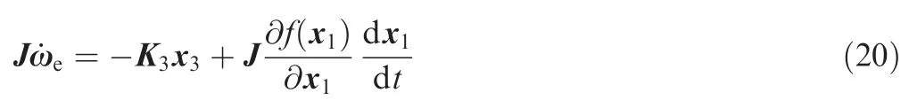
Step 4. Control torque design
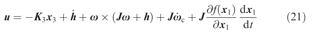
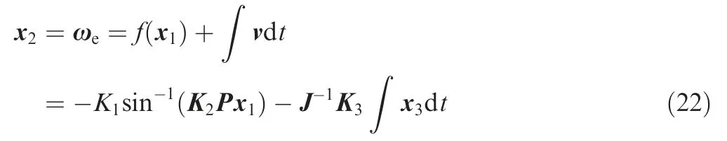
Considering Eqs. (11) and (19),can also be expressed as,
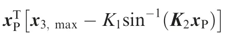
Substituting Eq.(8)into Eq.(20),the attitude controller is,
4.2. Analysis of virtual control input
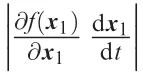
Because ultimately x2=f(x1), namely ωe=f(x1), the attitude controller u is related to f(x1)and the input v.As a result,f(x1)and v affect the dynamic tracking performance of the attitude controller.
The integral of Eq. (11c) is,
It is obvious that the dynamic tracking performance will worsen as K1, K2and K3increase. In particular, K1and K2are related to the convergence rate of f(x1)→0.
If the convergence rate of f(x1)→0 is too small, it cannot achieve the objective of ωe→0 in the current control cycle,meaning that ω has not meet the requirement of the last control cycle while ωchas been updated,resulting in the increasing of the error attitude, and the target spacecraft leaves the field of view.
Theoretically,faster convergence rates of f(x1)→0 are better. However, the capability of the attitude control actuator limits the corresponding convergence rate. If ωe→0 too rapidly, the actuator fails to produce the required control torque, and the attitude angular velocity error increases.
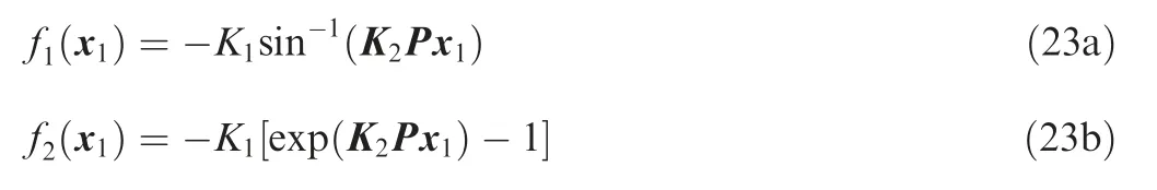
As for f(x1)=-K1sin-1K2Px1( ),the dynamic performance is influenced by the selection of K1and K2. Over a certain range, the attitude tracking error decreases and the convergence rate of ωe→0 increases with increasing K1. Similarly,the convergence rate of ωe→0 increases when K2decreases.
For comparison, we define,
4.3. Stability analysis
Considering Eqs. (11), the equilibrium point is(x1,x2,x3)=(0,0,0). From Eqs. (12) and (17), we have,
It can be seen that V1(x1,x2,x3)→∞as (x1,x2,x3)→∞,and we have,
According to the Lyapunov theorem,the equilibrium point(x1,x2,x3)=(0,0,0) is uniformly globally asymptotically stable.
5. Hybrid actuator system
5.1. Hybrid actuator system configuration
A hybrid actuator system consisting of CMG and RW is constructed in this paper.The CMG is able to generate large control torques, but a CMG cluster would trap into a singularity state,in which there is no output along its normal vector direction.19In addition, there is a saturation problem with RW,where the control torque cannot be guaranteed. The hybrid actuator system can address the problems mentioned above through the cooperation between the CMG and RW.
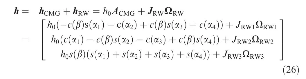
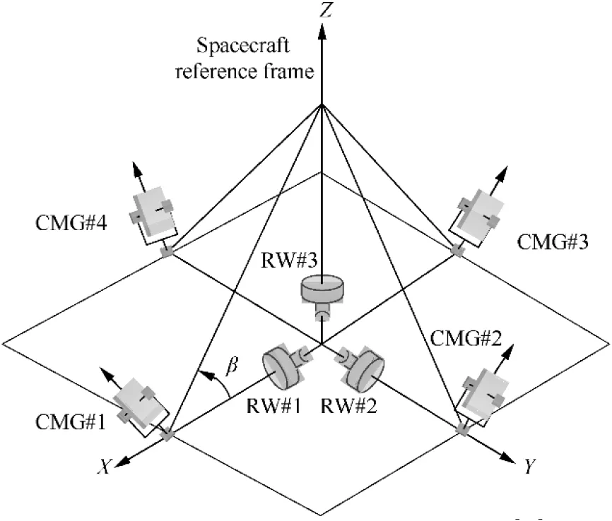
Fig. 2 Hybrid actuator configuration.10
The time derivative of Eq. (26) is,
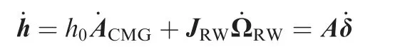
5.2. Steering logic
Eq. (28) can be represented as,


where the weighted matrix satisfies G=GT>0.Jais called the Jacobian matrix.When the CMG cluster traps into a singularity state,or rank Ja( )<3,the weighted pseudo-inverse steering logic is unavailable.However,the hybrid actuator system does not have the problem as rank Ja( )≡3.Therefore,the weighted pseudo-inverse steering logic for the hybrid actuator system can be rewritten as,

with weighted matrix W=WT.
It has been demonstrated that null motion can improve the efficiency of the CMG and RW,14especially for singularity escape, and therefore the null motion steering logic is proposed,

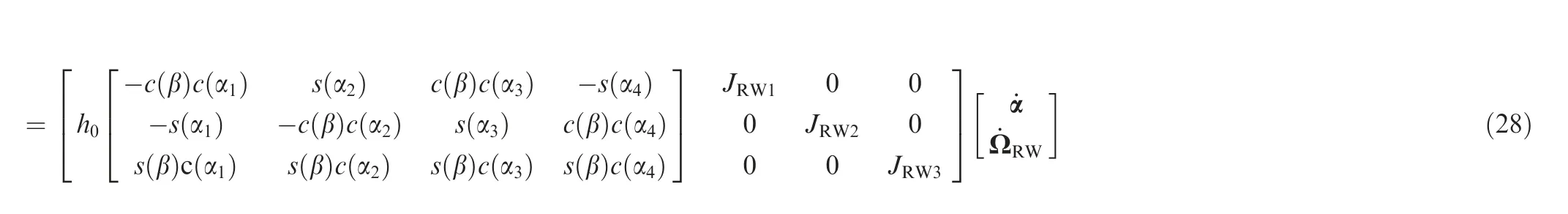
where ρ is the null motion strength, and d is the null motion vector,
In addition, the hybrid actuator dynamic performance Sactis set as,
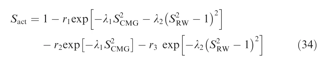
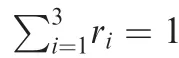
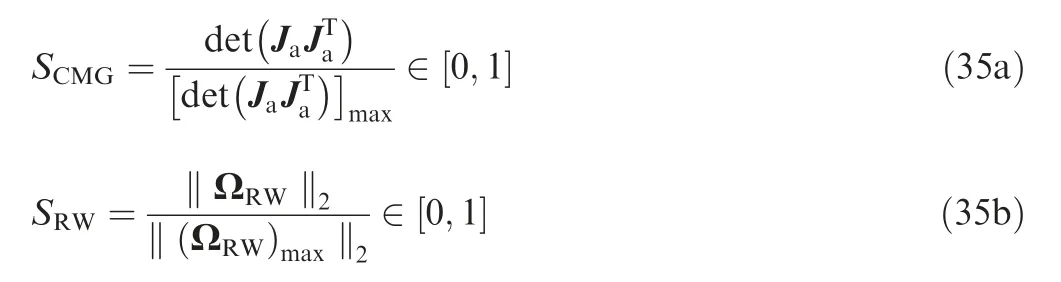
If SCMG=0,the CMG cluster traps into a singularity state,and if SRW=1, the RW saturation problem occurs.
6. Numerical simulation and analysis
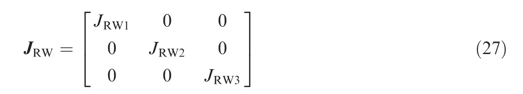
The moment of inertia of the spacecraft J and the moment of inertia of the RW are set as,
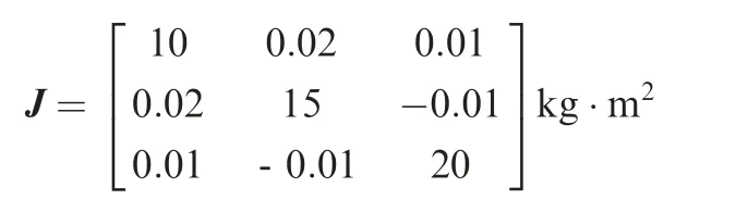
JRW=diag(0.005,0.005,0.005)kg·m2
The disturbance torque MDis selected as,
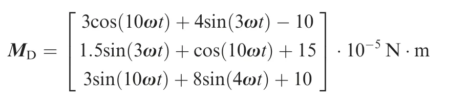
The maximum attitude angular velocity for the coarse phase ωmaxis 2(°)/s, and the attitude and attitude angular velocity measurement sensor accuracies are 0.005° and 0.001(°)/s, respectively. Supposing that the FOV (field of view) of the imaging camera is 0.1°,the attitude control accuracy therefore exceeds 0.05°.
The CMG flywheel momentum is 0.5 N·m, and the maximum torque is 0.5 N·m. The other parameters of the hybrid actuator are,
To restrict the acceleration and attitude angular,the saturation control method in Ref.15 is adopted for the coarse phase(0-50 s) in the simulation,
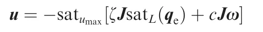
where ζ and c are positive parameters,and Umaxand L are the control constraints determined by the actuator output capacity. We choose c=4 and ζ=4.
In this section, five scenarios are considered. The virtual control inputs, simulation parameters, and actuator are summarized in Table 1.
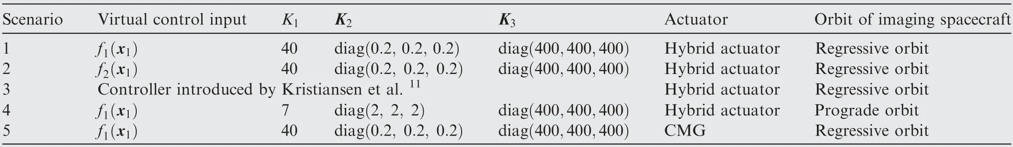
Table 1 Summarize of each simulation scenario.
The orbit elements of the imaging spacecraft and target are shown in Table 2.
The parameters of actuator steering logic are shown in Table 3. The hybrid actuator null motion steering logic is adopted in Scenarios 1-4 and the CMG null motion steering logic is adopted in Scenario 5.
The desired attitude, attitude angular velocity and orbit of imaging spacecraft and target of Scenarios 1-3 are shown in the Fig. 3(a)-(c), respectively.
The attitude adjustment and holding phase is from A to B,corresponding to 0 s to 50 s.In this phase,the desired attitude is (-58°, 81°, 0°).And the desired attitude angular velocity is ωc=[0, 0, 0](°)/s. Therefore, we set ωc=[0, 0, 0](°)/s for phase AB.
The target observation phase is from B to C at 500 s.In this phase,the maximum desired attitude angular velocity is about 4(°)/s.
The tracking mission is ended at the point C,then the imaging spacecraft returns to the Earth imaging mode from C to D at 600 s.In this phase,the desired attitude and attitude angular velocity are [0°, 0°, 0°] and ωc=[0, 0, 0](°)/s.
We defined the attitude adjustment and holding phase as phase AB, the target observation phase as phase BC and the Earth imaging phase as phase CD.
In Scenario 1,a combined control strategy consisting of the saturation controller and the improved backstepping controller is utilized for different phases, and the hybrid actuator is adopted as well. The simulation results for Scenario 1 are shown in Fig. 4(a)-(h).
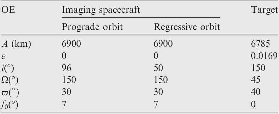
Table 2 Orbit elements of imaging and target spacecraft.
In phase AB, the saturation controller is utilized. The attitude tracking error and the angular velocity error decreased rapidly such that the spacecraft maneuvered rapidly to prepare for the target observation, where ωmax=2(°)/s and umax=0.5 N·m. In phase BC, the improved backstepping controller is implemented. The attitude tracking error and the angular velocity error converged to 0 to track the target for observations with high dynamic accuracy. The angular velocity error and the attitude tracking error reached 0.005°and 0.008(°)/s,respectively.In phase CD,the tracking mission is finished and the saturation controller is utilized again. The jump phenomenon of attitude tracking error appeared since the desired attitude changed to (0°, 0°, 0°) immediately.The spacecraft maneuvered in rest-to-rest mode with ωmax=2(°)/s. The initial condition of CMG α=[-105°, 10°, 95°, 170°] is in the neighborhood of a hyperbolic singularity. Fig. 4(e)-(f) show that the CMG momentum did not cross the neighboring singularity surface and went far away from the singularity state. The control at point C is caused by the change of the desired attitude.

Table 3 Parameter of actuator steering logic.
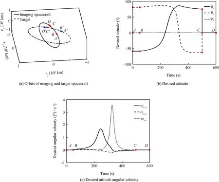
Fig. 3 Reference inputs of Scenarios 1-3.
The virtual control input for Scenario 2 is selected as f2(x1).The simulation results for Scenario 2 are shown in Fig. 5(a)-(d). Please note that the actuator performance index, control torque and control torque error are similar to those of Scenario 1 and are therefore not presented here for conciseness.
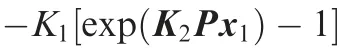
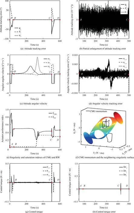
Fig. 4 Simulation results of Scenario 1.

Fig. 5 Simulation results of Scenario 2.
In Scenario 3,the controller introduced by Raymond Kristiansen in Ref.11is adopted for comparison.However,the utilized hybrid actuator is a combination of RW and thrusters.To compare the backstepping controllers proposed in this paper, the same hybrid actuator consisting of a CMG and RW is considered in this simulation. The simulation results for scenario 3 are shown in Fig. 6(a)-(d).
The controller in Ref.11was adopted in phases AB,BC and CD.The capability of actuator is not considered and therefore the spacecraft angular velocity reached 7(°)/s in phase AB,and the control torque reached 1.5 N·m,which was far beyond the agility of spacecraft. In phase BC, the angular velocity error and the attitude tracking error reached 0.02°and 0.01(°)/s,respectively, which are larger than that of Scenario 1.Because the performance of the virtual input in Ref.11is worse than the virtual input in this paper,besides,the term Px1is unnecessary as well.
In Scenario 4,the imaging spacecraft is in a prograde orbit while the target is still in the regressive orbit. Therefore, the desired attitude angular velocity is much larger than Scenario 1, which is about 6(°)/s. The simulation results for Scenario 4 are shown in Fig. 7(a)-(h).
In this scenario,f2(x1)is chosen as the virtual control input due to the large desired angular velocity.In phase BC,the larger desired attitude angular velocity required larger control torque. The maximum attitude tracking error and attitude angular velocity tracking error are 0.006°and 0.02(°)/s,respectively.Fig.7(h)shows that the hybrid actuator can provide the large control torque without trapping into singularity state.
Finally, only CMG is used as the actuator for Scenario 5,which is used to demonstrate the advantages of the hybrid actuator proposed in this paper. The simulation results for Scenario 5 are shown in Fig. 8(a)-(e).
We can see that the maximum attitude error for the tracking phase was more than 5° with a corresponding attitude tracking error of approximately 4(°)/s after 300 s,which is far beyond the mission requirement. This bad situation is caused by the singularity of the CMG, as shown in Fig. 8(c). It is obvious that the CMG-only actuated spacecraft is not capable for space moving target tracking mission.
The comparisons of the above five scenarios are summarized in Table 4.
The above comparisons of each simulation scenario are shown as follows:
(A) The first three scenarios satisfied the attitude tracking requirement, but the maximum attitude error for Scenario 3 reached approximately 0.02°, which was larger than these of the other two scenarios. Scenarios 1 and 2 although have the same attitude and attitude angular velocity tracking errors, the virtual control input f2(x1) for Scenario 2 is more widely applicable than f1(x1) for Scenario 1. Therefore, these three attitude control algorithms are ranked as 2, 1 and 3.
(B) The CMG-only actuated system cannot perform the attitude tracking mission and this strategy are therefore ranked as not available.
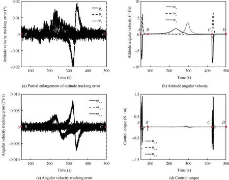
Fig. 6 Simulation results of Scenario 3.
(C) The orbit of the imaging spacecraft in Scenario 4 is different from Scenario 1, thus Scenario 4 ranked as not comparable.
(D) The proposed hybrid actuator system was able to provide accurate attitude control torques for the attitude tracking mission in this paper and both the CMG singularity and RW saturation can be avoided.
(E) The proposed control method fully considers the characteristic of different phases in attitude tracking mission,and the hybrid actuator CMG+RW is adopted for large output control torque.Therefore,the high tracking accuracy is guaranteed.
The detail comparisons to Ref.10are as follows:
(A) The tracking accuracy of the proposed controller is

(B) The expression of the proposed controller is simpler than the expression of Ref.10, and therefore computation cost is reduced in this paper.
7. Conclusions
In this paper,an improved backstepping controller with different virtual control inputs for attitude dynamic tracking of a moving space target has been proposed and analyzed.The attitude control was divided into two phases,which were a coarse alignment phase and a fine alignment phase. To guarantee large outputs and rapid rotational maneuverability of the spacecraft with high precision,the spacecraft is actuated using the hybrid actuator consisting of a CMG and RW. Null motion steering logic was adopted to address the CMG singular problem and RW saturation problem simultaneously. The simulation results demonstrated that the proposed controller and actuator configuration performs better than the controller designed in the references.

Fig. 7 Simulation results of Scenario 4.
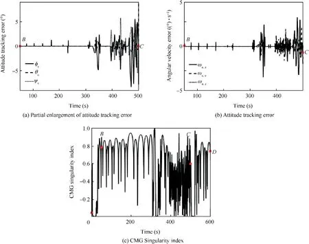
Fig. 8 Simulation results of Scenario 5.
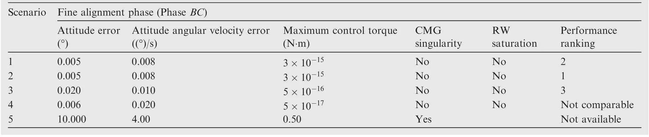
Table 4 Comparison of the simulation results among the five scenarios.
Acknowledgements
The authors would like to express their acknowledgement for the support provided by the National Natural Science Foundation of China (No. 61973153), the National Key Research and Development Plan of China (No. 2016YFB0500901),and the Open Fund of the National Defense Key Discipline Laboratory of Micro-Spacecraft Technology of China (No.HIT.KLOF.MST.201705).
 CHINESE JOURNAL OF AERONAUTICS2019年10期
- CHINESE JOURNAL OF AERONAUTICS的其它文章
- Design and analysis of a hypersonic inlet with an integrated bump/forebody
- Experimental study of effect of post processing on fracture toughness and fatigue crack growth performance of selective laser melting Ti-6Al-4V
- Efficient and accurate online estimation algorithm for zero-effort-miss and time-to-go based on data driven method
- Experimental and numerical investigation of threedimensional vortex structures of a pitching airfoil at a transitional Reynolds number
- A methodology for simulating 2D shock-induced dynamic stall at flight test-based fluctuating freestream
- Robust adaptive compensation control for unmanned autonomous helicopter with input saturation and actuator faults