Interaction of Wave Trains with Defects?
2019-03-12 02:41:46XianWeiChen陳賢偉PengFeiLi李鵬飛XiaoPingYuan袁曉平YeHuaZhao趙葉華JunMa馬軍andJiangXingChen陳江星
Xian-Wei Chen (陳賢偉), Peng-Fei Li (李鵬飛), Xiao-Ping Yuan (袁曉平), Ye-Hua Zhao (趙葉華),Jun Ma (馬軍), and Jiang-Xing Chen (陳江星)
1Department of Public Elementary Education, Zhejiang Guangsha College of Applied Construction Technology,Dongyang 322100, China
2Information Engineering School, Hangzhou Dianzi University, Hangzhou 310018, China
3Department of Physics, Hangzhou Dianzi University, Hangzhou 310018, China
4Department of Physics, Lanzhou University of Technology, Lanzhou 730050, China
(Received December 2, 2018; revised manuscript received December 19, 2018)
Abstract The evolution and transition of planar wave trains propagating through defects (obstacles)in an excitable medium are studied.When the frequency of the planar wave trains is increased, three different dynamical regimes,namely fusion, “V” waves, and spiral waves, are observed in turn and the underlying mechanism is discussed.The dynamics is concerned with the shapes of the defects.Circle, triangle, and rectangle defects with different sizes are considered.The increase of pacing frequency broadens the fan-shaped broken region in the behind of a rectangle defect.The increase of width of a triangle defect leads to breakup of wave trains easier while the change of height shows opposite effect, which is presented in a phase diagram.Dynamical comparison on defects with different shapes indicates that the decrease of the defect width along the propagation of wave trains makes the fan-shaped region and the minimal frequency for breakup of spiral both increased.
Key words: planar wave trains, defects, fusion, “V” pattern, spiral wave
1 Introduction
Nonlinear waves in excitable media are ubiquitous.[1?5]The emergence of defects in cardiac tissue, such as complex anatomical structures, blood vessels, and even scars from tissue damage, may lead to serious life-threatening consequences.[6]The defects (obstacles)give rise to the breakup of propagating wave trains initiated from the pacemaker, and subsequently results in formation of spiral waves.It is difficult to remove the pinned spirals on the defects, which represents ectopic pacing and tachyrhythmia.[7]In some cases, the defects also lead to breakup of spiral and consequent chaotic state, which is the precursor of lethal ventricular fibrillation.[8?9]Therefore, the studies on the interaction of traveling wave with defects had attracted much attention.
The interaction of wave trains with an anatomical defect can be quite complex especially in the spatiotemporally chaotic state associated with spiral turbulence.[7,10?11]Indeed, experiments concerning defects in cardiac tissue have yielded various results.[12?16]For example, some experiments reported that small defects do not affect spiral waves but,as the size of the defect is increased, such a wave can get pinned to the defect.[17]Various other experiments have been done to discuss the role of an anatomical defect as an anchoring site for spiral waves, which showed reducing the defect size or prolong the wavelength promotes complex oscillations,conduction failure, and leads to complex spiral wave behavior.[6,18]Simulations in excitable media showed that the rotating frequency and pulse behavior were size dependent in circular domain.[19?20]By starting with a large defect and decreasing its radius, a continuous transition was created from periodic motion to a modulated period-2 rhythm,and then to spiral wave breakup.These results may provide a useful basis for refining cardiac ablation techniques currently in use.[21?22]
Although great progress has been made on this topic in recent years,[10?13,23?25]it is still open for its complexity and significance.When the planar wave trains(PWTs)interact with a defect, the shape and size of the defect play an important role in determining the dynamics of interaction while it has not been studied so far.In this paper,we examine the evolution and transition of the PWTs propagating through several kinds of defects in an excitable medium.We chose circle, triangle, and rectangle defects with different sizes.The PWTs breaks into two parts when it collides with a defect.Subsequently,the two broken ends of the wave front show interesting behavior,which depends on the frequency of the excitation wave as well as the shape and size of the defects.The underlying mechanism about transition of patterns will be discussed.
2 Model and Method
The simulation of an excitable medium is performed in terms of a modified FitzHugh-Nagumo model (the B¨ar model).[26]This simplified mono-domain model is given by
whereuis the fast variable corresponding to membrane potential, andvis a slow variable corresponding to a recovery process.In this modelf(u,v)= (1/ε)u(1?u)[u ?(v+b)/a], andg(u,v)describes a delayed production of inhibitor withg(u,v)=?vfor 0≤u <1/3,g(u,v)= 1?6.75u(u ?1)2?vfor 1/3≤u <1, andg(u,v)= 1?v, foru >1.Numerical simulations are carried out on 256×256 2D grid points by employing the explicit Euler method.The space and time steps are△x=△y= 0.390 625 and△t= 0.02, respectively.Noflux condition is imposed on the boundaries.εis the ratio of their temporal scales which characterizing the excitability of the medium.In our simulation, we fix parametersε= 0.02,a= 0.84,b= 0.07.An unexcitable area by means of no-flux condition was defined in the middle of the system as the defect.
Three types of defects are considered,i.e.circular,triangular (up and down triangles), and rectangular defects.Periodic local pacing is utilized on the bottom boundary by applying a signal Γ=Acosωton a line containing gridsu(1?256,1)whereAandωare the amplitude and the angular frequency of the periodic pacing, respectively.PWTs are stimulated from the boundary of the system to mimic the waves from a pacemaker.The frequency of the PWTs is equal to that of the local pacing.When the pacing frequency increases a critical value, it is shown that the output wave train can no longer follow each excitation pulse of the pacing, namely, the system output cannot keep 1:1 frequency relation with the input, rather it can generate only 1:n(nis larger than or equal to 2)frequency response.We record the critical frequency asω0.
3 Results and Discussion
The first examination is the propagation of PWTs through a circular defect.When we increase the value of pacing angular frequencyω, three different parameter regimes can be distinguished by the pattern of the excitation wave.When the frequency of the local pacing is not very high, such asω=0.81ω0in Fig.1(a), the PWTs break when they encounter the front of the defect and form two broken ends.Upon circumnavigating the defect, the two broken ends of the wave front come together and fuse with small pits.Subsequently, the wave front thus recovers its previous shape and moves on.Now if we continue to increase the frequencyω, the system would experience an interesting evolution.Wave chains of “V” configuration withω= 0.90ω0appear in Fig.1(b).It is obvious that the wavelength of the“V”wave trains is greatly increased.Ifωis increased further,two counter-rotating spirals withω=0.93ω0in Fig.1(c)are observed in the behind of the defect, respectively.

Fig.1 (Color online)Dynamical patterns of the planar wave trains propagating through a circular defect(radius R=15△x with three different pacing frequencies ω,i.e.,ω= 0.81ω0 in (a), ω= 0.9ω0 in (b), and ω= 0.93ω0 in(c), at t= 300.The arrow shows the direction of the propagating wave trains.
To understand the propagation of PWTs and observed patterns in Fig.1,we present the dynamics evolution withω=0.93ω0in Fig.2.After initial process of fusion beforet=80 in Fig.2(a),it is shown that many broken ends cannot touch each other again after they propagate through the circular defect as that in Fig.2(b)att=86.That is because the wave trains with high velocity(sinceω=0.93ω0approachesω0)are drag down by the defect and the two ends collide with considerable overlap (one can find this point by comparing Fig.1(a)with Fig.2(b)), which gives rise to a refractory region resulting from the dispersion relation at the back of the defect.[27]The two broken ends depart each other when they propagate around the refractory region and then fuse again when they pass through it, as shown in Fig.2(b)att=86 and Fig.2(c)att=100.In the behind of the defect, a region with sparse waves appears, which can be seen in Figs.2(c)and 2(d).This region grows up and two counter-rotating tips are formed in Figs.2(d)and 2(e).Ultimately, two counter-rotating spiral waves are observed in Fig.2(e).Note that the region that initial wave trains cannot enter into has fan-shaped configuration, which is consistent with the simulation in Ref.[28] where the train waves cannot propagate into the the fan-shaped region in the behind of the defect to suppress the turbulence.
Now, we consider the propagation of PWTs through a rectangle defect.The phenomenon is similar with that through the circular defect: when the frequency of pacing is increased, three different dynamical regimes are observed, as shown in Figs.3(a)–3(c).The area of the fanshaped region can be characterized by the central angleθwhich is illustrated in Fig.3(b).Interestingly, it is shown that the increase ofωmakes the increase of fan-shape region.Comparing Fig.3(b)with Fig.3(c), one can see this point.We calculate the dependence ofθonω/ω0.The curves in Fig.3(d)shows that the values ofθincrease quickly asω/ω0.Simulation finds that the transition from“V”waves to spiral waves occurs whenθis aboutπ/2.Asω/ω0gradually reaches 1.0, theθapproaches an asymptotic value 2π/3.

Fig.2 (Color online)The time evolution shows the wave breakup and formation of a pair of counter-clock rotating spirals on a circular defect at t= 80 (a), t= 86 (b),t= 100 (c), t= 120 (d), t= 140 (e), and t= 300 (f).Other parameters: R=15 △x and ω=0.93ω0.

Fig.3 (Color online)Patterns of PWTs interacting with a rectangle defect with height (H= 30 △x)and width(L= 30 △x)at t= 300.The pacing frequencies are ω= 0.81ω0 in (a), ω= 0.83ω0 in (b), and ω= 0.88ω0 in (c), respectively.(d)The dependence of the central angle θ of the fan region on the ω/ω0.The definition of the θ is shown in (b).
On an up-triangle defect, the wave trains also experience three dynamical regimes when the pacing frequency is increased, which is illustrated in Figs.4(a)–4(c).Once a planar wave encounters the defects, it is split into two parts.Subsequently, the two ends move along the edge of the triangle with decreased width.On the vertex of the triangle,the two ends touch each other and then leave the triangle, as that in Fig.4(a).In Fig.4(b), one can see the “V” trains initiate from the vertex of the triangle.If we fix the height of the triangle (H), while increase the width of the base of the triangle (L), the two ends will experience more pronounced change when they propagate on the defect, from splitting to fusion, which gives rise to the breakup of wave trains.This point is confirmed in Fig.4(d)where the minimal frequency for the formation of“V”wave trains decreases when theLis increased.Thus, the increase of the width of a triangle defect may result in breakup of wave trains easier.In Fig.4(e), we present the phase diagram in the H-L plane with fixedω/ω0.With small width, i.e.L= 5, the wave trains always fuse in the behind the defect, even the height of the defect is increased much.With the increase of width, i.e.L= 10, the PWTs can form “V” wave in the behind of the defect.In this case,increase of the height may quickly lead to the fusion of the wave train on the defect.WhenLis large, three different regimes appear in turn in the phase diagram if the values ofHare increased.For fixedH, increase ofLwill give rise to the formation of “V”wave and counter rotating spiral waves.From the phase diagram, one can get a conclusion that increase ofHmay contribute to the propagation of PWTs by preventing the formation of “V” wave and spiral waves, while increase ofLleads to the breakup of PWTs and formation of “V”wave and spiral waves.
To study the influences of defect shape on the propagation of PWTs further, we present four types of defects in Fig.5.For comparison, we set their widths and heights same.It is shown that different shapes of defect result in different minimal frequencies.The value ofωmin(= 0.082ω0)is smallest in the down triangle, that means this type of defect is the most dangerous shape for breakup of wave trains when the facing frequency is increased.Theωminof a rectangle is slight bigger.For the circular defect,the value ofωminis greatly increased to 0.93ω0.The up triangle defect has the biggestωmin(=0.96ω0), which indicates this shape is much safer than other shapes.From the comparison, it seems that the narrowing of a defect may contribute to the persistence of waves train with high frequency.The phenomena can be qualitatively discussed in terms of the linear Eikonal relations
whereCpandCare the velocities of a propagating wave(K≠0)and a planar wave (K=0), respectively,Dis the diffusion coefficient, andKis the local curvature of the propagating wave.[29]When the wave trains reach the position on obstacles with maximal length,the situations are different in four cases.In Figs.5(a)and 5(b),the two broken waves depart from the obstacle suddenly while they gradually leave the narrowing defects in Figs.5(c)and 5(d).In Figs.5(a)and 5(b), besides the initial propagating velocity, the broken ends show rapid growing tangential velocities that decrease their propagating velocities.Subsequently, the ends become bend with increased curvatureK.Then,CPis decreased, which leads to increased refractory time in the behind of the obstacle.[30]Consequently,the waves trains break with lower frequencyωmin.As to the case in Fig.5(c), especially the case in Fig.5(d), the narrowing of defect is slow.The effect is not obvious, which results in biggerωmin.
On the other hand, the area of the fan-shaped region in the behind of the defect is increased from Fig.5(a)to 5(d).The fan-shaped region in Fig.5(a)is similar with that in Fig.5(b).It is interesting that the area is increased dramatically when the defects become narrower along the propagation of the wave train.Note that if turbulence exists in this fan-shaped region, local pacing is difficult to suppress they.
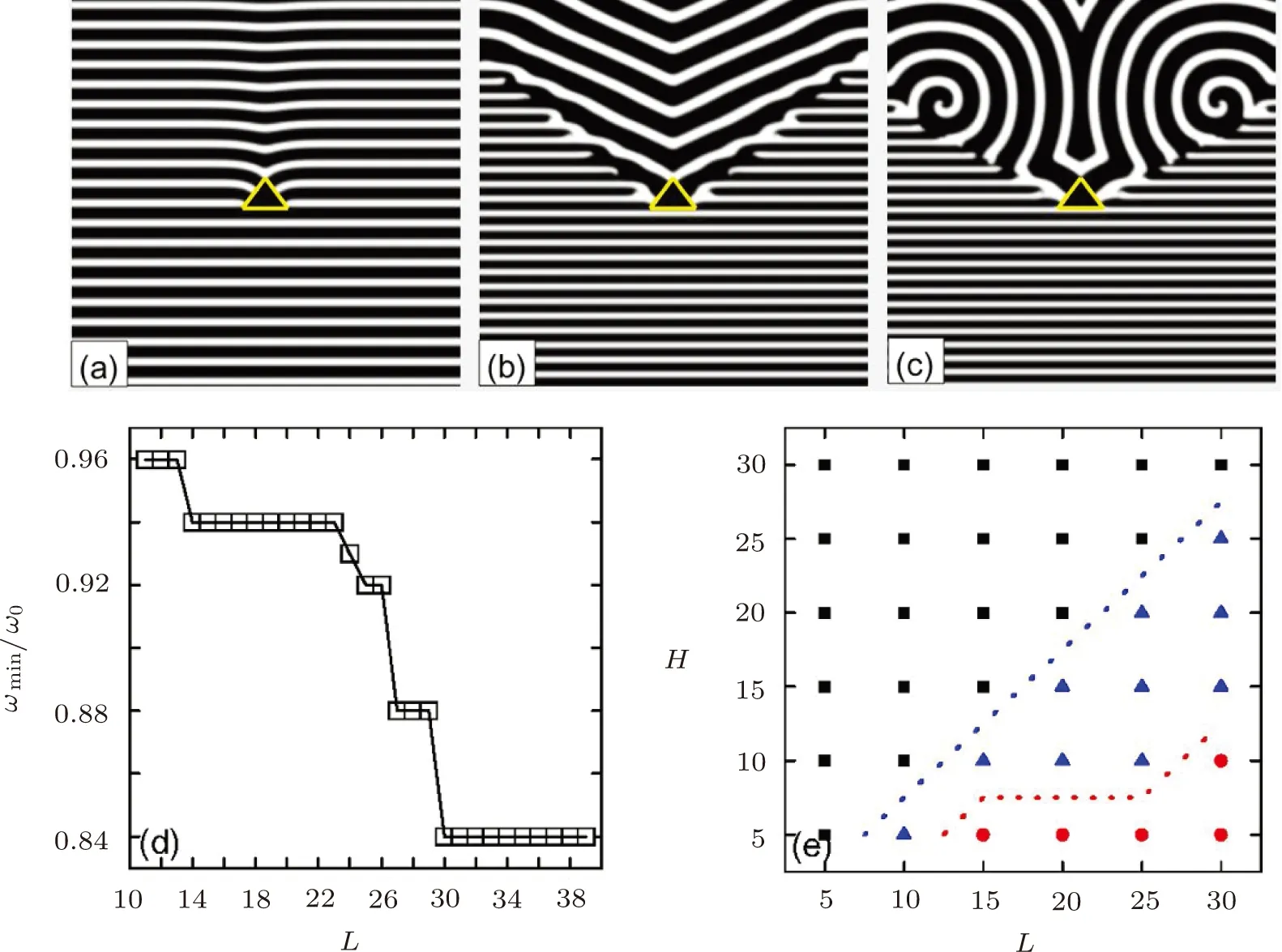
Fig.4 (Color online)Patterns of PTWs interacting with an up-triangle defect with height (H= 20 △x)and width(H= 30 △x)at t= 300.The pacing frequencies are ω= 0.81ω0 in (a), ω= 0.93ω0 in (b), and ω= 0.964ω0 in (c),respectively.(d)The dependence of ωmin/ω0 on the defect width L.The PWTs fuse after colliding with the defect when ω <ωmin while they break as ω >ωmin.The height of the triangle H is fixed to be H=10 △x.(e)The phase diagram in the H-L plane describes three dynamical regimes with ω=0.94ω0.The square, triangle, and circle mean the states of fusion, breakup to “V” pattern, and two counter-rotating spirals, respectively.

Fig.5 (Color online)Patterns of wave trains interacting on defects with different shapes.The pacing frequencies are ω/ωmin= 0.82 in (a), ω/ωmin= 0.83 in (b), ω/ωmin= 0.93 in (c), and ω/ωmin= 0.96 in (d), respectively.The size is H=L=R=30 △x.
4 Conclusion
In conclusion, we have studied the evolution and transition of planar wave trains propagating through four kinds of defects in an excitable medium.Based on the frequency of a local pacing, three dynamical regimes are distinguished in terms of the pattern formation in the behind of the defects: fusion, “V” pattern, and two counter-rotating spirals.The dynamical process is discussed.For a rectangle defect, the area of fan-shaped region decreases with the increase of local pacing.For a triangle defect, the increase ofLmakes the wave train easier to breakup at lowerωmin.Also, we present a phase diagram to illustrate the influences of height (H)and width (L)of the triangle defect.The increase of width gives rise to the breakup of wave trains to form “V” pattern and spirals, while the increase of width is beneficial for the fusion of the wave trains.The narrowed defect along the propagation of the wave results in two effects: the minimal frequency for breakup of wave trains and the area of the fan-shaped region are both increased.Although the shapes of defects in cardiac tissue are complex, we hope the results studied here may contribute to the understanding of interaction between the wave trains from the pacemaker and defects.
 Communications in Theoretical Physics2019年3期
- Communications in Theoretical Physics的其它文章
- Entropy Quantization of Schwarzschild Black Hole
- Pull-in Instability Analysis of Nanoelectromechanical Rectangular Plates Including the Intermolecular, Hydrostatic, and Thermal Actuations Using an Analytical Solution Methodology
- Boundary Layer Flow over a Curved Surface Imbedded in Porous Medium
- Spin-Dependent Electron Tunneling in ZnSe/Zn1?xMnxSe Heterostructures with Double δ-Potentials
- Modulated Dust-Acoustic Wave Packets in an Opposite Polarity Dusty Plasma System
- A Modified Gravity Theory: Null Aether?