Overview of Co-Design Approach to RF Filter and Antenna
2018-04-27 02:51:52
ZTE Communications 2018年1期
(Shanxi University,Taiyuan 030006,China)
1 Introduction
Miniaturization and low cost are the two most fundamental demands for the radio frequency(RF)receiver front-end.Nowadays,dual-function or multifunction integrated modules become more and more popular in wireless communication systems for their miniaturized circuit size and satisfying overall performance.For example,the noise figure of a RF antenna-filter low-noise-amplifier(LNA)system has been significantly improved with the co-design strategy[1].In[2],antennas were co-designed with the amplifier and transceiver to attain higher integration degree.The filter and the antenna are independent component inmost of the RF front-end.The antenna is used to receive and transmit signal,and the bandpass filter is cascaded right after the antenna for filtering the spurious signals.Generally,the bandpass filter and antenna are designed separately and connected by a 50 Ω transmission line.This transmission line not only degrades the performance of the system but also occupies the additional circuit area.Recently,many scholars have begun to study the co-design method for the bandpass filter and antenna.Based on the open literatures,it is possible to categorize co-design approach in five main categories:1)Codesign by optimizing the interfacing impedance;2)co-design according to the synthesis approach of filter;3)co-design by embedding novel resonators within the feeding structures;4)co-design by employing auxiliary physical structures;5)other methods.
2 Survey and Analysis
2.1 Co-Design by Optimizing the Interfacing Impedance
One of the simply co-design way by optimizing the interfacing impedance between the filter and antenna is displayed in Fig.1.Here,the filter and antenna are layered and share the same ground plane to reduce the dimensions[3].The advantages of this co-design approach are that the miniaturized dimensions can be obtained compared to the version before the co-design.Also,the design process of the filter and antenna is mutually independent.By optimizing the impedance at the interfaces of the filter and antenna,the performance can be improved.Various integrated filtering antennas using this method have been reported[3][6].An example has been developed in[3].The S11and gain before and after the co-design are shown in Fig.2.It can be seen that,for the co-designed version,the measured passband is located at 4.064.26 GHz.As compared to 4.034.14 GHz for the traditional version,a wider bandwidth is obtained.Meantime,the corresponding peak gain is4.3 dBi,better than 2.8 dBi for the traditional version.

▲Figure1.A co-designed filtering antenna.
2.2 Co-Design According to the Synthesis Approach of Filter
In this approach,the last stage of filter network is replaced with an antenna which acts as one of the resonators.The synthesis and design process is same as the filter.The advantages of this approach are that the realized filtering antenna has a high integration degree.The disadvantages are,in some designs,extra filtering circuits are inserted to the antenna feeding networks,causing extra insertion loss and degrading antenna gains.
Many of the filtering antennas according to the synthesis approach of filter use the micro strip structure[7][15].Most of them obtained compact dimensions,such as 0.41lg×0.6lg[12]and 0.23lg × 0.29lg[13].A typical example and corresponding results can be found in Fig.3[9].It is demonstrated that this simple filtering antenna possesses a flat realized gain response within its operational band and has good band-edge selectivity.
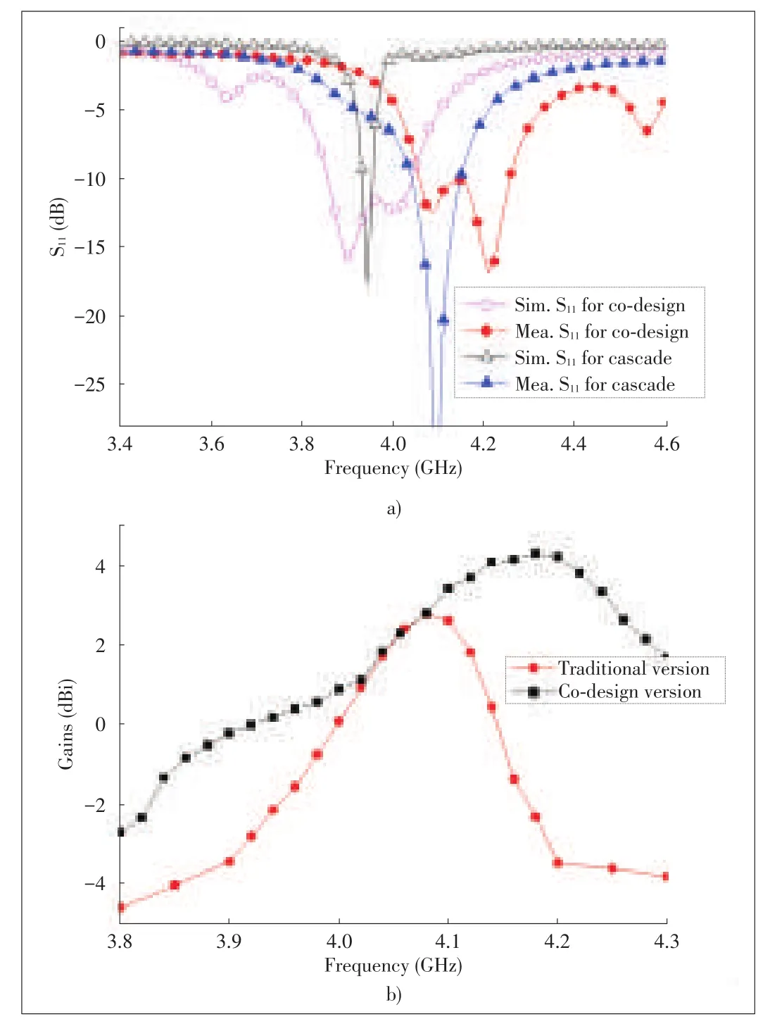
▲Figure2.a)Measured and simulated S11 and b)Measured gains for the co-designed and traditional filtering antennas.
This co-design method can also be used for filtering antennas fed by coplanar waveguide(CPW)[16][18]and filtering dielectric resonator antennas.Especially in[17],a reconfigurable filtering slot antenna(FSA)is designed.Its structure and results are shown in Fig.4[17].Compared to the ordinary slot antenna,the proposed FSA has a wider bandwidth,flat antenna gain in the passband,and good frequency skirt selectivity in both states.
Recently,this co-design method is applied for designing the filtering micro-strip antenna array[19],[20].In[20],two filtering microstrip antenna arrays fed by a uniform/nonuniform power divider network have been designed,fabricated,and measured.Fig.5 displays its photograph fed by a uniform power divider network[20].Both the antenna arrays have achieved good impedance matching characteristic as well as filtering response,such as a flat gain frequency response,sharp band edge characteristic,and high stop band suppression.The filtering antenna array fed by a nonuniform power divider has presented a low sidelobe performance.
▲Figure3.a)The first electricals mall filtering antenna and b)measured and simulated|S11|and realized gain values of the filtering antenna.
▲Figure4.a)Layout of the proposed reconfigurable filtering slot antenna and b)simulated and measured S11 and gain of the FSA for OFF and ON states.
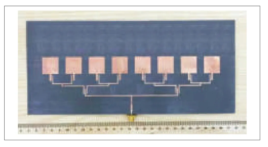
▲Figure5.Photograph fed by auniform power divider network.
2.3 Co-Design by Embedding Novel Resonators Within the Feeding Structures
In order to control the performance of filtering patch antennas,many designs embed the resonator within the feeding structure of antenna.The advantages of this approach are that its design can be more flexible and free.Also,since no complex filtering and matching networks are involved,the proposed dual-band filtering antenna is very compact and the insertion loss of feeding circuit is desirably low.
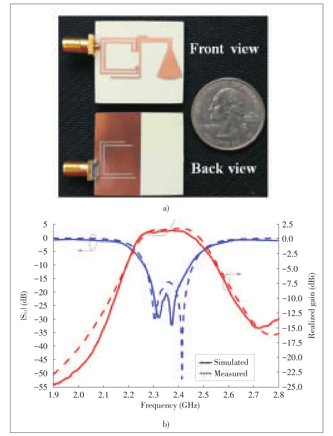
This approach is often used to realize multi-band and UWB filtering antennas[21][28].Typical planar structure can be found in[23].Its configuration and the corresponding S11,gain are shown in Fig.6[23].It can be seen that the two operating bands locate at 1.9 GHz and 2.6 GHz for LTE applications.The out-of-band gains are less than 10 dBi,indicating more than 16 dB out-of-band radiation rejection levels,which can meet the requirement of LTE MIMO for customer premise equipment(CPE).It is also seen that radiation nulls are generated at 1.85 GHz and 2.10 GHz for the lower band,and 2.50 GHz and 2.91GHz for the upper band,resulting in better filtering performance for two bands.
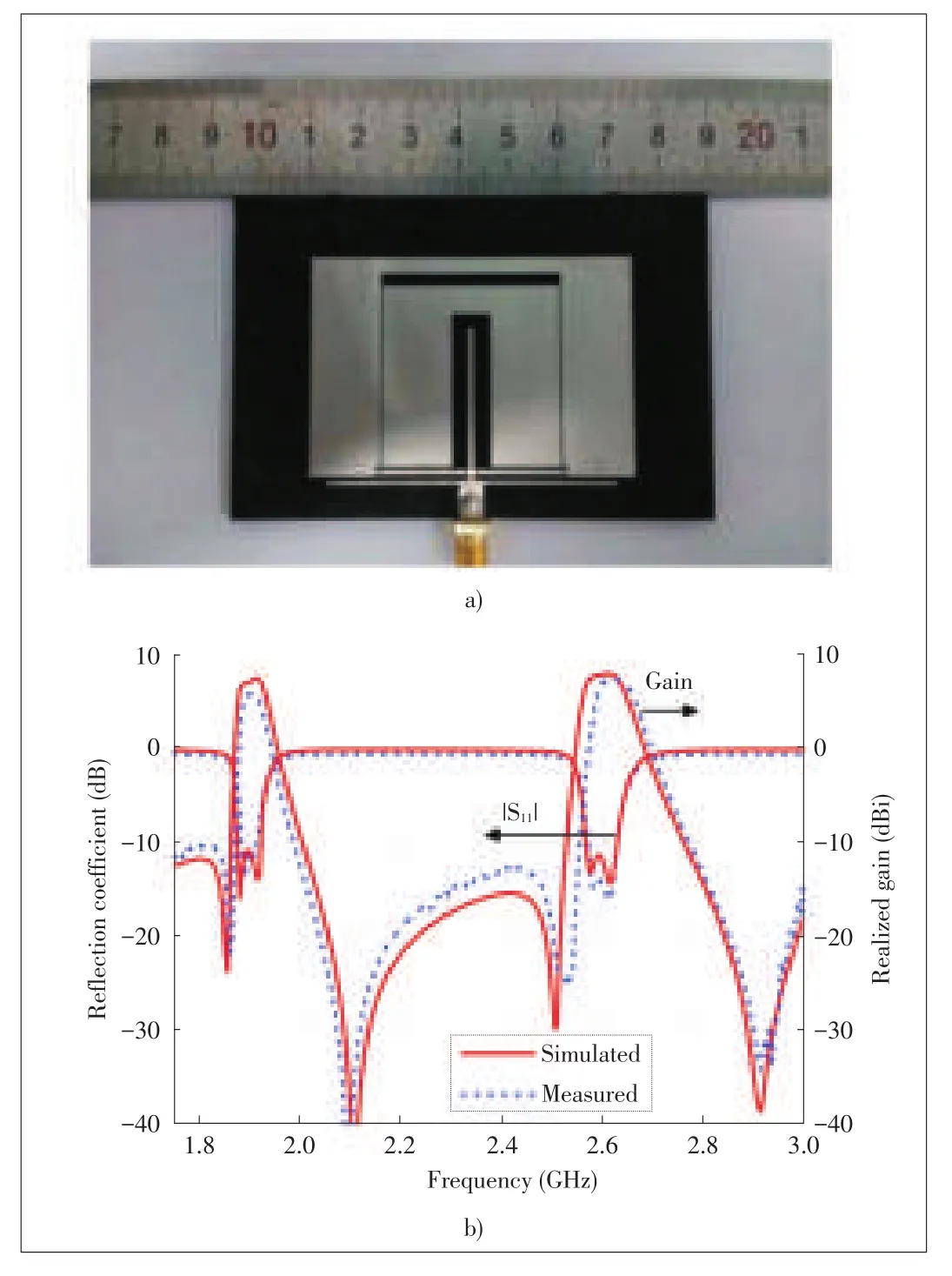
▲Figure6.a)Fabrication prototype of the dual-band filtering antenna and b)simulated and measured results of the proposed antenna.
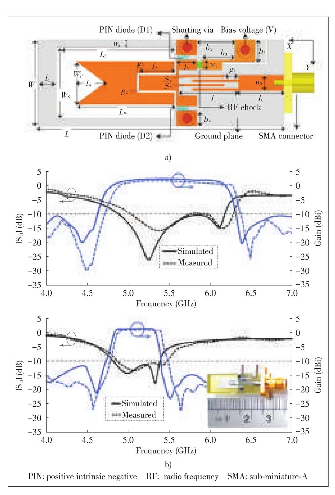
It is worth mentioning that in[28],the tunability has been achieved by centrally loading the resonator with only a single varactor diode(Fig.7).Since the frequency tuning technique is achieved at the feeding line of the antenna without affecting the antenna radiation characteristics,the radiation patterns are stable over the interesting frequency range.This makes the proposed filter-antenna convenient for the interweave Cognitive Radio(CR)communication applications.In addition,in[24],a filtering antenna which consists of the conventional microstripfed monopole antenna and the recently developed high frequency selective two-stage filter based on the twist modified Split Ring Resonator(SRR),is demonstrated in Fig.8.To filter out the unwanted out-of-band radiation,the used filter unit is inserted directly into the feeding line of the monopole antenna without adding extra space.
This co-design method can also be used for the filtering dielectric resonator antenna(DRA)[29][31].The common performance of three designs are that they show better second harmonic suppression,with out-of-band suppression of more than 23 dB within very wide stopband.To the best of our knowledge,it is the broadest passband and stopband that can be obtained thus far from a simple co-designed broadside filtering antenna.Fig.9 shows the interesting filtering circular polarization(CP)antenna in[31].Here,the coupled line sections are introduced on the flexible snowflake shaped patch element to obtain wideband,excellent bandpass filtering and harmonic suppression characteristics.A hollow DRA is integrated with this coupler for the implementation of a wideband filtering CP antenna.The realized antenna exhibits a wide overlapping bandwidth of 27.8%.Moreover,the proposed antenna achieves a wide stopband up to the third harmonics with a suppression level larger than 19 dB.
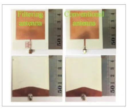
▲Figure8.Photographs(top view and back view)of the co-designed filtering antenna and the conventional planar printed monopole antenna.
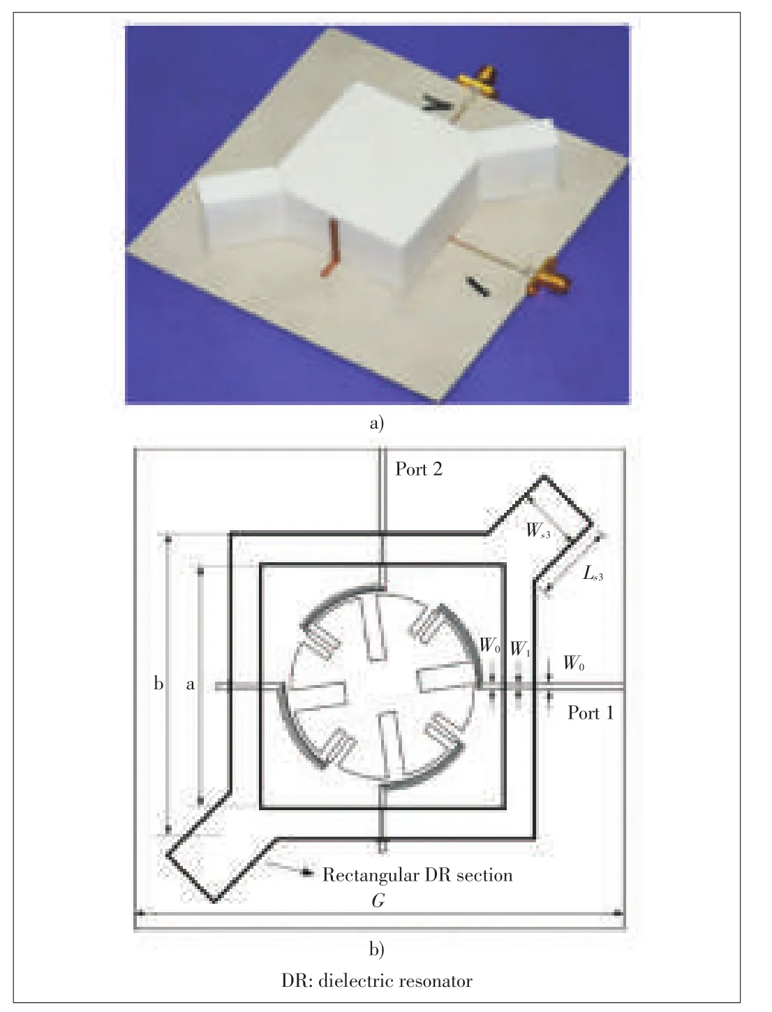
▲Figure9.a)Photograph of the designed wideband filtering CP antenna and b)configuration of the proposed wideband filtering CP antenna.
2.4 Co-Design by Em ploying Auxiliary Physical Structures
In order to improve the integration and reduce the insertion loss caused by inserting extra filtering circuits,filtering antennas by employing auxiliary physical structures are proposed[32][35].Since no extra filtering circuit is involved,the antenna is very simple.Moreover,due to eliminating insertion loss of filtering elements,this type of filtering antennas can provide a relatively high-gain.
In this co-design approach,the auxiliary physical structures can be merged with the original antenna[32]or realized in the driven patch[33],[34].For example,in[32],the filtering antenna is realized by adding a parasitic loop to a unidirectional loop antenna.As a result,two radiation nulls in the gain curve versus frequency are obtained at the lower and upper band-edges,showing enhanced skirt selectivity.In[33],as a high efficient radiator,the metasurface is elaborately designed to provide a sharp roll-off rate at upper band edge for the filtering function.In[34]and[35],a filtering antenna composed of a driven patch and a stacked patch is proposed.In the driven patch,three shorting pins and a Uslot are embedded to enhance out-of-band suppression and skirt selectivity near the lower band-edge,whereas the stacked patch provides a sharp roll-off rate at the upper band-edge and also an enhanced gain.
2.5 Other Methods
In addition,there are other kinds of filtering antenna,such as horn filtering antenna[36]and substrate integrate waveguide(SIW)filter-antenna[37][40].In[36],the single and dual-band split-ring resonator(SRR)etched on a Rogers Duroid RT5870 dielectric substrate are inserted within the metallic flare of the horn at a proper distance from the throat.At the resonant frequencies of the SRR,transmission is highly reduced and the notched bands are obtained.For the SIW filter-antenna,it is demonstrated that the co-design can be used to reduce the transmission loss,enhance bandwidth and suppress signals of adjacent frequency band.This antenna array can be used as mm-wave front end which demands for compact size and low noise disturbing.
3 Conclusions
An overview of reported filtering antenna in open literatures has been presented.As the requirement for various applications grows,there are a greater number of filtering antennas that can be classified in a wide range of different types.This article reports the filtering antennas based on the co-design approaches.It is demonstrated that the co-design is an efficient method to improve the integration degree,reduce the size and cost,and optimize the performance.
[1]S.Alalusiand R.Brodersen,“Antenna-filter-CMOS LNA co-design strategy,”in Proc.CPD2000,Zurich,Switzerland,2001,pp.8187.
[2]J.J.Wang,Y.P.Zhang,K.M.Chua,and A.C.W.Lu,“Circuit model of microstrip patch antenna on ceramic land grid array package for antenna-chip co-design of highly integrated RF transceivers,”IEEE Transactions on Antennas and Propagation,vol.53,no.12,pp.38773883,Dec.2005.doi:10.1109/TAP.2005.859907.
[3]J.H.Zuo,X.W.Chen,G.R.Han,L.Li,and W.M.Zhang,“An integrated approach to RF antenna-filter co-design,”IEEE Antennas and Wireless Propagation Letters,vol.8,pp.141144,Jan.2009.doi:10.1109/LAWP.2009.2012732.
[4]C.X.Mao,S.Gao,Z.P.Wang,et al.,“Integrated filtering antenna with controllable frequency bandwidth,”in European Conference on Antennas and Propagation,Lisbon,Portugal,2015,pp.14.
[5]Z.H.Jiang,M.D.Gregory,and D.H.Werner,“Design and experimental investigation of a compact circularly polarized integrated filtering antenna for wearable biotelemetric devices,”IEEE Transactions on Biomedical Circuits and Systems,vol.10,no.3 pp.328338,Apr.2016.doi:10.1109/TBCAS.2015.2438551.
[6]L.Li and G.Liu,“A differential micro strip antenna with filtering response,”IEEE Antennas and Wireless Propagation Letters,vol.15,pp.19831986,Dec.2016.doi:10.1109/LAWP.2016.2547884.
[7]Z.H.Jiang and D.H.Werner,“A compact,wideband circularly polarized co-designed filtering antenna and its application for wearable devices with low SAR,”IEEE Transactions on Antennas and Propagation,vol.63,no.9,pp.38083818,Sept.2015.doi:10.1109/TAP.2015.2452942.
[8]Z.H.Jiang and D.H.Werner,“A co-designed wideband circularly polarized integrated filtering antenna,”in Asiapacific Microwave Conference,Nanjing,China,2015,pp.13.doi:10.1109/APMC.2015.7413370.
[9]M.C.Tang,Y.Chen,and R.W.Ziolkowski,“Experimentally validated,planar,wideband,electrically small,monopole filtennas based on capacitively loaded loop resonators,”IEEE Transactions on Antennas and Propagation,vol.64,no.8,pp.33533360,Aug.2016.doi:10.1109/TAP.2016.2576499.
[10]C.K.Lin and S.J.Chung,“A compact filtering microstrip antenna with quasielliptic broadside antenna gain response,”IEEE Antennas and Wireless Propagation Letters,vol.10,pp.381384,Apr.2011.doi:10.1109/LAWP.2011.2147750.
[11]L.Chen and Y.L.Luo,“Compact filtering antenna using CRLH resonator and defected ground structure,”Electronics Letters,vol.50,no.21,pp.14961498,Oct.2014.doi:10.1049/el.2014.2703.
[12]W.J.Wu,Y.Z.Yin,S.L.Zuo,Z.Y.Zhang,and J.J.Xie,“A new compact filter-antenna for modern wireless communication systems,”IEEE Antennas and Wireless Propagation Letters,vol.10,pp.11311134,Oct.2011.doi:10.1109/LAWP.2011.2171469.
[13]X.W.Chen,L.Y.Yan,and W.M.Zhang,“A compact filtering antenna with flat gain response within the passband,”IEEE Antennas and Wireless Propagation Letters,vol.12,pp.857860,Jul.2013.doi:10.1109/LAWP.2013.2271972.
[14]S.Chen,Y.Zhao,M.Peng,and Y.Wang,“A co-designed compact dual-band filtering antenna with PIN loaded for WLAN applications,”International Journal of Antennas&Propagation,vol.2014,pp.16,May 2014.doi:10.1155/2014/826171.
[15]B.Ding,X.Wei,C.Wang,M.Zhang,and Z.He,“A compact printed filtering antenna with flat gain using annular slot and UIR,”in 15th International Conference Electronic Packaging Technology(ICEPT),Chengdu,China,2014,pp.12521255.doi:10.1109/ICEPT.2014.6922871.
[16]W.Tian,J.Zhang,F.Zhang,and W.Chen,“Compact dual-band CPWfed filtering antenna for WLAN applications,”in 8th International Symposium on Computational Intelligence and Design(ISCID),Hangzhou,China,2016,pp.606609.doi:10.1109/ISCID.2015.93.
[17]M.M.Fakharian,P.Rezaei,A.A.Orouji,and M.Soltanpur,“A wideband and reconfigurable filtering slot antenna,”IEEE Antennas and Wireless Propagation Letters,vol.15,pp.16101613,Sept.2016.doi:10.1109/LAWP.2016.2518859.
[18]B.Sahu,P.Tripathi,S.Singh,M.K.Meshram,and S.P.Singh,“A simple structured filtering dielectric resonator antenna,”in IEEE Uttar Pradesh Section International Conference on Electrical,Computer and Electronics Engineering(UPCON),Varanasi,India,pp.543545,2016.doi:10.1109/UPCON.2016.7894712.
[19]A.K.Sahoo,R.D.Gupta,and M.S.Parihar,“A 2x2 integrated filter-antenna array,”in European Conference on Antennas and Propagation,Paris,France 2017,pp.22052208,doi:10.23919/EuCAP.2017.7928306.
[20]F.C.Chen,H.T.Hu,R.S.Li,et al.,“Design of filtering microstrip antenna array with reduced sidelobe level,”IEEE Transactions on Antennas and Propagation,vol.65,no.2,pp.903908,Feb.2017.doi:10.1109/TAP.2016.2639469.
[21]C.X.Mao,S.Gao,Y.Wang,et al.,“An integrated filtering antenna array with high selectivity and harmonics suppression,”IEEE Transactions on Microwave Theory and Techniques,vol.64,no.6,pp.17981805,May 2016.doi:10.1109/TMTT.2016.2561925.
[22]C.Y.Hsieh,C.H.Wu,and T.G.Ma,“A compact dual-band filtering patch antenna using step impedance resonators,”vol.14,pp.10561059,May 2015.doi:r 10.1109/LAWP.2015.2390033.
[23]X.Y.Zhang,Y,Zhang,Y.M.Pan,and W.Duan,“Lowprofile dual-band filtering patch antenna and its application to LTEMIMO system,”IEEE Transactions on Antennas and Propagation,vol.65,no.1,pp.103113,Jan.2017.doi:10.1109/TAP.2016.2631218.
[24]W.B.Cheng,“Compact2.4GHz filtering monopole antenna based on modified SRR-inspired high-frequency-selective filter,”Optik,vol.127,pp.1065310658,Jan.2016.doi:10.1016/j.ijleo.2016.08.086.
[25]S.Koley and D.Mitra,“A planar microstrip-fed tri-band filtering antenna for WLAN/WiMax applications,”Microwave and Optical Technology Letter,vol.57,no.1,pp.233237,Jan.2015.doi:10.1002/mop.28813.
[26]Y.M.Pan,P.F.Hu,X.Y.Zhang,and S.Y.Zheng,“A low-profile high-gain and wideband filtering antenna with metasurface,”IEEE Transactions on Antennas and Propagation,vol.64,no.5,pp.20102016,May 2016.doi:10.1109/TAP.2016.2535498.
[27]M.I.Sabran,S.K.A.Rahim,C.Y.Leow,et al.,“Compact circularly polarized truncated square ring slot antenna with suppressed higher resonances,”PLoS One,vol.12,no.2,pp.113,Feb.2017.doi:10.1371/journal.pone.0172162.
[28]H.A.Atallah,A.B.Abdel Rahman,K.Yoshitomi,and R.K.Pokharel,“Compact frequency tunable filtenna with wide continuous tuning range using capacitively loaded folded arms open loop resonator for interweave cognitive radio application,”in 33rd National Radio Science Conference(NRSC),Aswan,Egypt,Feb.2016,pp.8793.doi:10.1109/NRSC.2016.7450815.
[29]P.F.Hu,Y.M.Pan,X.Y.Zhang,and S.Y.Zheng,“Broadband filtering dielectric resonator antenna with wide stopband,”IEEE Transactions on Antennas and Propagation,vol.65,no.4,pp.20792084,Apr.2017.doi:10.1109/TAP.2017.2670438.
[30]P.F.Hu,Y.M.Pan,X.Y.Zhang,and S.Y.Zheng,“A compact filtering dielectric resonator antenna with wide bandwidth and high-gain,”IEEE Transactions on Antennas and Propagation,vol.64,no.8,pp.36453651,Aug.2016.doi:10.1109/TAP.2016.2565726.
[31]B.J.Xiang,S.Y.Zheng,Y.M.Pan,and Y.X.Li,“Wideband circularly polarized dielectric resonator antenna with bandpass filtering and wide harmonics suppression response,”IEEE Transactions on Antennas and Propagation,vol.65,no.4,pp.20962101,Apr.2017.doi:10.1109/TAP.2017.2671370.
[32]J.N.Wu,Z.Q.Zhao,Z.P.Nie,and Q.H.Liu,“A printed unidirectional antenna with improved upper band-edge selectivity using a parasitic,”IEEE Transactions on Antennas and Propagation,vol.60,no.4,pp.18321837,Jan.2015.doi:10.1109/TAP.2015.2392112.
[33]Y.M.Pan,P.F.Hu,X.Y.Zhang,and S.Y.Zheng,“A low-profile high-gain and wideb and filtering antenna with metasurface,”IEEE Transactions on Antennas Wireless Propagation,vol.64,no.5,pp.20102016,May 2016.doi:10.1109/TAP.2016.2535498.
[34]X.Y.Zhang,W.Duan,and Y.M.Pan,“High-gain filtering patch antenna without extra circuit,”IEEE Transactions on Antennas Wireless Propagation,vol.63,no.12,pp.58835888,Dec.2015.doi:10.1109/TAP.2015.2481484.
[35]W.Duan,X.Y.Zhang,Y.M.Pan,J.X.Xu,and Q.Xue,“Dualpolarized filtering antenna with high selectivity and low cross polarization,”vol.64,no.10,pp.41884195,Oct.2016.doi:10.1109/TAP.2016.2594818.
[36]M.Barbuto,F.Trotta,F.Bilotti,and A.Toscano,“Horn antennas with integrated notch filters,”vol.63,no.2,pp.781785,Feb.2015.doi:10.1109/TAP.2014.2378269.
[37]U.Naeem,A.Iqbal,M.F.Shafique,and S.Bila,“Efficient design methodology for a complex DRASIW filter-antenna,”International Journal of Antennas and Propagation,vol.2017,pp.19,Apr.2017.doi:10.1155/2017/6401810.
[38]Y.Chen,H.Wei,Z.Q.Kuai,and H.M.Wang,“Kuband linearly polarized omnidirectional planar filtenna,”IEEE Antennas and Wireless Propagation Letters,vol.11,pp.310313,Apr.2012.doi:10.1109/LAWP.2012.2191259.
[39]Y.Chen and H.Wei,“3738 GHz substrate integrated filtenna for wireless communication application,”Microwave and Optical Technology Letter,vol.54,no.2,pp.346351,Feb.2012.doi:10.1002/mop.26589.
[40]X.Liu,H.Wang,S.Quan,et al.,“Design of a W band filter-antenna array with low sidelobe level using gap waveguide,”in 11th International Symposium on Antennas,Propagation and EM Theory(ISAPE),Guilin,China,2016,pp.132134.doi:10.1109/ISAPE.2016.7833900.
- ZTE Communications的其它文章
- ZTE Communications Guidelines for Authors
- Wireless Data and Energy Integrated Communication Networks
- Behavior Targeting Based on Hierarchical Taxonomy Aggregation for Heterogeneous Online Shopping Applications
- Phase Locked Loop Based Cancellation of ECG Power Line Interference
- Secure Beamforming Design for SWIPT in MISO Full-Duplex Systems
- Recent Advances of Simultaneous Wireless Information and Power Transfer in Cellular Networks