On the Procedures for the Demonstration of the RF Safety of Active and Passive Implants in MRI Environments
2016-02-07 03:24:08EugeniaCABOTMariaCABANESSEMPERENielsKUSTER
中國醫療設備 2016年4期
Eugenia CABOT,Maria CABANES-SEMPERE,Niels KUSTER,3
1.IT'IS Foundation,Zeughausstrasse 43,8004 Zurich,Switzerland;2.Zurich MedTech AG,Zurich,Switzerland;3.Swiss Federal Institute of Technology (ETH),R?mistrasse 101,8092 Zurich,Switzerland
On the Procedures for the Demonstration of the RF Safety of Active and Passive Implants in MRI Environments
Eugenia CABOT1,Maria CABANES-SEMPERE2,Niels KUSTER1,3
1.IT'IS Foundation,Zeughausstrasse 43,8004 Zurich,Switzerland;2.Zurich MedTech AG,Zurich,Switzerland;3.Swiss Federal Institute of Technology (ETH),R?mistrasse 101,8092 Zurich,Switzerland
As a diagnostic method,magnetic resonance imaging (MRI) is not allowed to be used in patients with medical implants,including both active implants (such as cardiac defbrillators or deep brain stimulators) and passive implants (such as orthopedics implants and support).MRI imaging scanning can produce magnetic felds,which will produce concentrated electromagnetic induction on metal edges of the implants,such as electrodes.The magnetic feld can also signifcantly increase the temperature of surrounding tissues.Besides,the currents and voltage produced by active implants when exposed to MRI scanning can lead to damage and malfunction of pulse generators.Therefore,patients with medical implants cannot receive MRI as a diagnostic method.This safety protocol prevents a large group of patients from receiving MRI diagnosis.This leads to the conclusion that the safety evaluation of implants under MRI environment requires the combination of accurate data analysis and experimental techniques so as to establish the standard testing program.
magnetic resonance imaging;implants;radiofrequency safety;protocol
0 INTRODUCTION
Magnetic resonance imaging (MRI) is a medical diagnostictechnique that allows the noninvasive examination of patients.MRI produces detailed images of internal organs and provides better contrast for soft tissues than other imaging techniques.However,this diagnostic tool is contraindicated in patients benefiting from therapies involving implantation of medical devices,be those active (like pacemakers or deep brain stimulators) or passive (like orthopedic implants and stents).The electromagnetic (EM) felds produced by the MRI scanner induce currents in the metallic parts of the implants,which will concentrate at sharp edges,e.g.,at the electrodes,and could signifcantly increase the temperature of the surrounding tissue.In addition,for active implants,induced currents and voltages could damage or cause malfunction in the pulse generator units.
Therefore,patients with medical implantsare excluded from MRI diagnostics,unless they having implants labeled "MRI safe" by regulatory bodies.This exclusion criterion would potentially affect a considerable portionof the population.According to the statistical study performed by Raatikainenet al[1]the mean value of pacemaker implantations per million inhabitants was 532 in 2013 (maximum and minimum implantation rate were 1218 and 14,respectively)(The dataset was collected by the European Heart Rhythm Association (EHRA).It only includes the countries belonging to the European Society of Cardiology (ESC),and it is specific to pacemaker implantations).Implantation rates have been escalating for the past years for different implant types[2],so the design of MRI safe implants would beneft a continuously increasing number of patients.
1 METHODS
The assessment of the safety of implants in an MRI environment requires a combination of precise numerical and experimental techniques.Standards have to be established to describe the testing procedures.
1.1 TS 10974
The technical specifcation of the ISO/IEC intends to give guidance for the assessment active implantable medical devices (AIMD) safety in MRI environments.The TS 10974 focuses on RF tissue heating and EMC effects.The frst edition of the TS was published in 2012,and the second edition is expected to be on print in 2015.The RF safety evaluations described in the frst edition of the TS were divided in four (4) tiers,higher tier methods having increasing complexity,but offering lessconservative results.The four tier approach feasibility was analyzed in[3],and the study proved the utility of the procedures.However,many aspects of the procedures for safety assessment remained open.
The second edition contains a revisedversion of the Tier-3 procedure,which will be discussed below,in Section 3.A fowchart summarizing the steps for Tier-3 evaluation of active implants can be found in Figure 1.
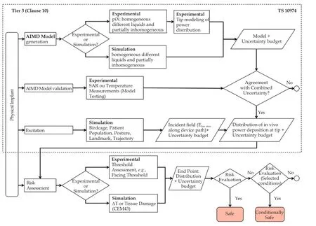
Figure 1 Flowchart of the safety assessment procedure following tier 3 of the TS 10974.
1.2 ASTMF2182
For passive implants,the ASTM F2182[4]provides guidelines for testing the tissue heating during MRI RFexposure and RF-related heating of a significant number of passive implants.In this test method,the whole implant is exposed to a uniform electric field and thein vitrotemperature increase reported.This testing criterion is only suitable for the evaluation of electrically small implants,i.e.,implant dimensions much smaller than the effective wave length in media,where no significant phase variation of the incident field along the implant is expected during MRI exposure.
A test case for the application of ASTM F2182 is given in Section 4.
2 IMPLANT SAFETY ASSESSMENT OF ACTIVE IMPLANTS FOLLOWING THE ISO/TS 10974
2.1 Generation of the AIMD transfer function
For the safety evaluation of active implants following the Tier-3 approach in the TS 10974,the electrical characterization of the implant is needed.The implant can be electrically characterized by obtaining a transfer function that will transform any E-feld condition incident to the implant into the induced power at the electrode due to that incident condition.The transfer function can be obtained either experimentally or numerically[5].
In order to experimentally determine the transfer function,the piX System (ZMT Zurich MedTech AG,Zurich) is used.The system,which consists of a control unit,a phantom,an excitor or antenna and a measuring probe,is shown in Figure 2.The implant is positioned inside the phantom on the yellow racetrack provided to facilitate the fxation.The probe measures the response in the proximity of the electrodes to local excitation produced by the antenna at locations all along the length of the implant.The response of the system to each of the local excitations along the implant is measured at the proximity of the electrodes.The obtained response is the resulting transfer function.A different transfer function is measured for each electrode of the implant under evaluation.
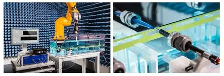
Figure 2 The system consists of a control unit,a phantom,an excitor or antenna and a measuring probe.Left: Pix system setup: control unit,phantom,antenna and measuring probes;Right: Detail of the measuring probes in the vicinity of an electrode.
The transfer function can be also obtained in silicowith full-wave simulations.In Figure 3 the magnitude and phase of the transfer function of generic implants obtained numerically (with Sim4Life) and experimentally (with the PiX system) are shown.The generic implants are three wires with lengths 400,600 and 800 mm.The transfer functions obtained experimentally and numerically show excellent agreement.
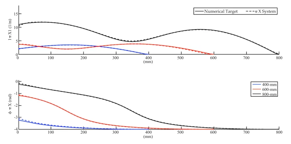
Figure 3 Transfer function of three generic implants (wires of lengths 400 mm,600 mm and 800 mm),obtained numerically (solid line) and experimentally (dashed line).
2.2 Validation of the AIMD transfer function
The transfer function needs to be validated for a suffciently large set of orthogonal test functions,to ensure that it is a sound electrical representation of the implant for any incident conditions.
The test functions are incident field conditions that canbe generated in a laboratory measurement environment.The implant is stress-tested experimentally with the set of incident conditions and the power induced at the tissue simulating liquid surrounding the electrodes is obtained and compared to the one computed with the transfer function.The generation of the incident conditions in the experimental environment is performed with a birdcage coil like the Medical Implant Test System (MITS,ZMT Zurich) in combination with testing phantoms that allow the generation of several testing conditions.Figure 4 shows the MITS and different phantoms in which the testing conditions are generated.
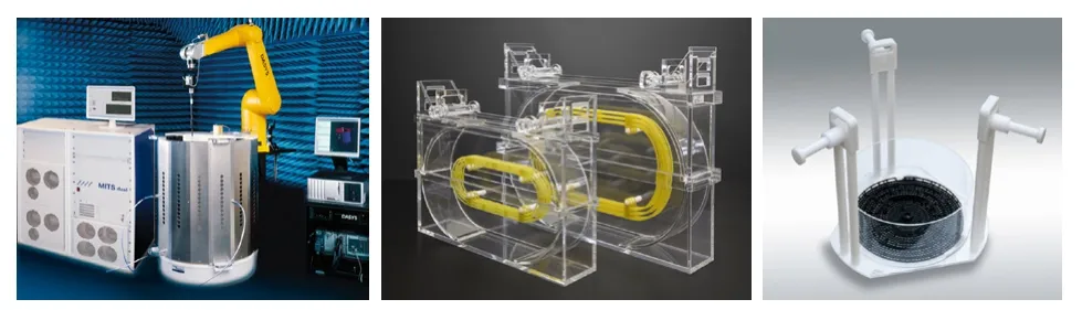
Figure 4 The MITS and different phantoms in which the testing conditions.Left: Birdcage coil and control unit of the Medical Implant Testing System (MITS);Right: Several testing phantoms used to produce a comprehensive set of incident conditions for the transfer function validation.
2.3 Computation of the incident felds for the patient population
The ultimate goal of the AIMD safety assessment is to estimate the power delivered to the tissue surrounding the electrodes when the implant is inside a patient.The approach described in TS 10974 requires that the risk assessment of RF heating covers a wide range of the population,located in different landmark positions corresponding to imaging procedures,in a range of RF birdcages covering the existing clinical scanners;all in all a broad coverage of anatomies,landmarks and coil geometries.The computable anatomical models of the Virtual Population[6-7]are functionalized for morphing and posing,enabling the user to obtain a wide and representative patient population with realistic and clinically relevant postures.The choice is not limited to standard male and female subjects in child-hood or adult-hood,but includes an elderly male and an obese one,the latter being most important for worst-case evaluations inside an MRI volume coil.Human models belonging to the Virtual Population are found in Figure 5.
The incident (tangential) electric felds along the lead of an AIMD need to be calculated for all possible routing paths that are plausible for the clinical implantation of the device in the body.The extracted felds tangential to the clinical routing paths are the incident conditions to be applied to the transfer function of the implant for the estimation of thein vivodeposited power at the electrodes of the implant for realistic clinical situations (Figure 6).

Figure 5 Human models of the virtual population.
2.4 Risk assessment for RF heating
Implant manufacturers need to transform the data collected after the exhaustive testing and simulation campaigns into a risk assessment for the device under test.The risk assessment can be performedin vivo,by means of animal studies,or in silico,with numerical simulations.
For the animal studies,the power obtained as a result of the safety assessment is injected into the electrodes of an implanted animal.The variation in the measured pacing threshold is the parameter used for the risk assessment.If the in silico approach is chosen the power deposited in the electrodes is translated into thein vivotemperature increase in humans by means of thermal simulations.Figure 7 shows the results of a thermal simulation performed with Sim4Life.
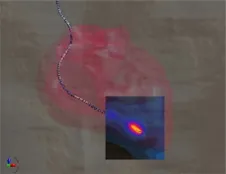
Figure 7 Example of thermal distribution around the electrode of a cardiac lead in a human model exposed to the fields generated by a birdcage coil.
3 IMPLANT SAFETY ASSESSMENT OF PASSIVE IMPLANTS FOLLOWING THE ASTMF2182
The ASTM F2182-11a standard[4]establishes the test methods for the assessment of Radio Frequency induced heating in the environment of passive implants during MRI.The standard defines the protocols to perform temperature measurements in the vicinity of passive implants positioned in a rectangular shaped phantom known as the "ASTM phantom".This phantom traditionally had a smaller secondary rectangle positioned on the top part of the bigger rectangle,in a manner as to mimic a head.Currently,a single rectangle is accepted as container for the tissue simulating medium (TSM),which is a saline gelled solution.The nominal TSM dielectric properties specifed in the standard are an electrical conductivity of 0.47% ±10 % S/m and a relative permittivity varying from 60 to 100,for the two operating frequencies covered by the ASTM F2182,i.e.,64 MHz and 128 MHz.
The F2182 standard recommends the implant placement in a location where the E-feld is known and with a suffciently high magnitude as to produce a temperature increase of at least 10 times the precision of the temperature probe at the chosen location without the presence of the implant.Another recommendation is to position the implant with its longest dimension parallel to the direction of the E-field,and,as possible,in a region where the undisturbed E-feld (i.e.without implant) does not vary significantly at the planned location of the implant.To identify the high E-field regions in the phantom,the standard recommends to obtain an E-field map computationally or experimentally.Figure 8 shows the E-feld distribution at the central coronal slice of the phantom.
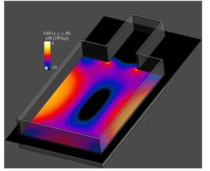
Figure 8 SAR distribution on central slice of ASTM phantom exposed to 1.5T birdcage coil in the absence of the implant.
The highest E-fields are located closer to the phantom walls.However,locating a scatterer (implant) close to the interface of the phantom is far from being ideal,due to field refections and heat transfer to the environment.The standard states that keeping the implant at least 20 mm away from any interface is a good compromise.Figure 9 shows the location of a generic spine fusion implant[7]inside the ASTM phantom and the SAR distribution around the implant for 1.5T exposure.
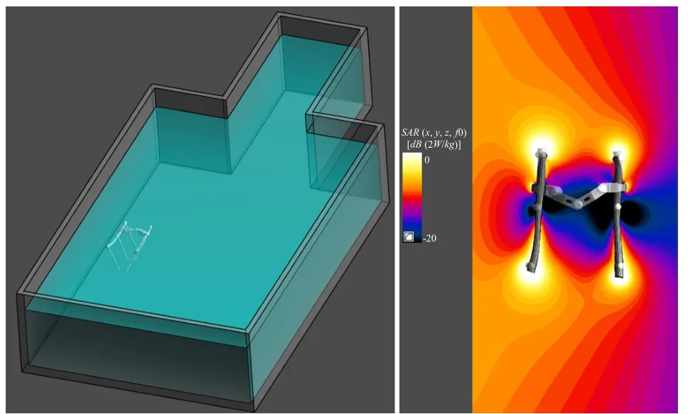
Figure 9 The location of a generic spine fusion implant[7]inside the ASTM phantom and the SAR distribution around the implant for 1.5T exposure.Left: Location in the ASTM phantom of a generic passive implant consisting on three pairs of pedicle screws for spinal fusion[7];Right: SAR distribution around the implant for MRI RF exposure at 1.5 T.
Temperature probes must be placed at the locations ofinterest.Simulations are used to establish where the locations with maximum temperature rise are found in the vicinity of the implant.The temperature probes should be located at these positions.It is also advised to monitor the background temperature increase in the phantom by locating temperature probes away from the implant region.Figure 10 shows the temperature increase distribution around the implant and the temperature increase as a function of time at the top of the left rod.For a incident uniform SAR at the location of the implant of 1 W/kg the temperature increase goes as high as 0.7 °C after 15 min exposure.
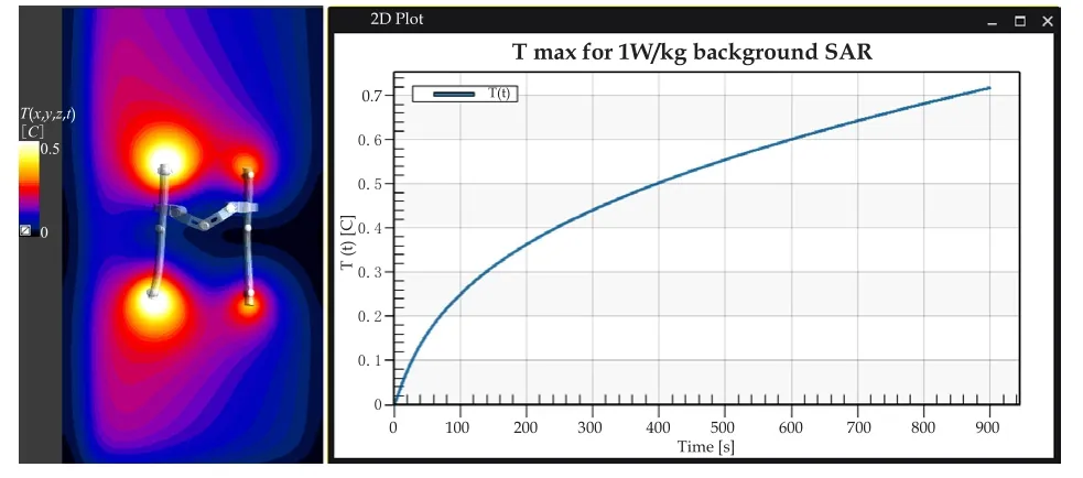
Figure 10 The temperature increase distribution around the implant and the temperature increase as a function of time at the top of the left rod.Left: Temperature distribution around implant location for 1.5T RF MRI exposure during 900 s;Right: Temperature increase as a function of time at the location of the maximum when the implant is exposed to RF from the 1.5T birdcage.
4 CONCLUSIONS
The safety assessment of medical devices requires a set of well defned and precise procedures.In this paper a review of the current standards for active and passive medical devices has been performed.The TS 10974 of the second edition lists the steps to follow for the safety evaluation of active implants.The procedures combine experimental and numerical techniques for the estimation of power deposition andin vivotemperature rise in the vicinity of the electrodes of the implant leads.The ASTM F2182 is limited to the evaluation of short passive implants.The standard describes the steps to be followed for the performance of temperature measurements,and recommends the use of numerical tools to assess feld patterns and location of hotspots.In this paper we have gone through the test methods stated in these two standards showing the application of the procedures for two generic implants.
[1]Raatikainen MJP,Arnar DO,Zeppenfeld K,et al.Statistics on the use of cardiac electronic devices and electrophysiological procedures in the European Society of Cardiology countries: 2014 report from the European Heart Rhythm Association[J].Europace,2015,17(s1):i1-i75.
[2]Lubinski A,Bissinger A,Boersma L,et al.Determinants of geographic variations in implantation of cardiac defbrillators in the European Society of Cardiology member countries-data from the European Heart Rhythm Association White Book[J].Europace,2011,13(5):654-662.
[3]Cabot E,Lloyd T,Christ A,et al.Evaluation of the RF heating of a generic deep brain stimulator exposed in 1.5 T magnetic resonance scanners[J].Bioelectromagnetics,2013,34:104-113.
[4]ASTM F2182-11a.Standard test method for measurement of radio frequency induced heating on or near passive implants during magnetic resonance imaging[M].ASTM International,West Conshohocken,PA,2011.
[5]Zastrow E,Cabot E,Kuster N.Assessment of local RF-induced heating of AIMDs during MR exposure[A].2014 31thURSI General Assembly and Scientifc Symposium[C],URSI GASS 2014.
[6]Christ A,Kainz W,Hahn EG,et al.The Virtual Familydevelopment of surface-based anatomical models of two adults and two children for dosimetric simulations[J].Phys Med Biol,2010,55(2):N23-38.
[7]Gosselin MC,Neufeld E,Moser H,et al.Development of a new generation of high-resolution anatomical models for medical device evaluation:the Virtual Population 3.0[J].Phys Med Biol,2014,59(18):5287.
R318.08 [Document Code]A
10.3969/j.issn.1674-1633.2016.04.004
1674-1633(2016)04-0018-05
Received: 2015-11-30
Niels Kuster,Founder &Chairman,IT'IS Foundation.E-mail: kuster@itis.ethz.ch