Design of SMA actuator of stem structure for flower robot
2015-12-19 08:48:34Hao1eiHUANGDongpengSHUYingnaLUODepartmentofMechanicalEngineeringChongqingIndustryPolytechnicCollegeChongqing401120China
機床與液壓 2015年12期
Hao-1ei HUANG,Dong-peng SHU,Ying-na LUO(Department of Mechanical Engineering,Chongqing Industry Polytechnic College,Chongqing 401120,China)
Design of SMA actuator of stem structure for flower robot
Hao-1ei HUANG*,Dong-peng SHU,Ying-na LUO
(Department of Mechanical Engineering,Chongqing Industry Polytechnic College,Chongqing 401120,China)
The flower robot,a household service robot,has been main focus of our research.Generally,the flower robot has the appearance of a common flower which consists of the petal,the stem,and the leafage.Besides having the appearance of a flower,the flower robot has the following functions,such as a moving mechanism,a sensing ability,and a home appliance function.Especially,the moving function is very important function among the various functions.The moving function of flower robot consists of the bending of stem,the blooming of petal and the stirring of the leafage.This paper,focuses on the movement of the flower robot structure.As an actuator for flower structure,coil type Shape Memory Alloy(SMA)is adopted and silicone stem,petal and leafage structures with 6 coil type SMA are proposed.Firstly,using SMA actuator,the flower structure are designed and fabricated.Secondly,the kinematic equation such as stem,petal and leafage are derived.Then,through the kinematic equation the control system can be designed to drive the flower robot by Dspace.Finally,through the experiment,the feasibility of the system is proven,and its performances are evaluated.
Shape memory alloy(SMA),Actuator,Flower structure,Control system
Hydromechatronics Engineering
http://jdy.qks.cqut.edu.cn
E-mail:jdygcyw@126.com
1 Introduction
Generally,the flower robot has the appearance of a common flower which consists of flower,stem and leaves.Besides the appearance of the flower,the flower robot has the following functions such as moving mechanism,sensing ability,and home appliance function.Firstly,the sensing function of flower robot can recognize the environmental conditions such as room temperature,pressure,voice and light intensity. Secondly,the moving function of the flower robot can mimic the blooming of flower,the swaying of the stem and the stirring of the leaves in the wind.Thirdly,the home appliance function can include a humidifier,a vision/voice recording system and an illumination.
For the flower robot,the development of the moving function is very important,and this paper is focused on the moving mechanism of the flower robot.The motion of the flower robot is divided the blooming of flower,the swaying of the stem and the stirring of the leafage and petal.Especially,this paper focuses on the swaying of the stem and proposes-new moving mechanisms of stem structure for a flower.For the actuation of moving function,coil Shape Memory Alloy(SMA)is adopted and a silicone rod structure using 4 SMA is proposed.
SMA is a smart material that has the shape memory effect.After a sample of SMA has been deformed from its original crystallographic configuration,it regains its original geometry by itself during heating.The range of applications for SMA has been increasing in recent years,and the major areas are industry,medicine,and navigation[1-3].One major application of SMA is actuator which has the very high power-to-weight ratio.In addition,high possibility of miniaturization and low power consumption are salient properties of SMA actuator.Accordingly,this class of actuators is widely researched and employed to various fields[4].Pfeiffer etal.proposed SMA robot prostheses such as shoulder and fingers[5],Mascara and Asada presented a wet SMA actuators for active vacuolated robotic flesh[6],and Byungkyu etal.suggested an earthworm-like micro robot using SMA actuator[7].In current existing SMA propel designs such as active palpation sensor[8],biomimetic vehicle[9],and actuated composite beam[10],moulds in industrialized production and mechanical fishes,the control of the movement directions are by all means to be the least complicated.Most of the designs follow axial movements,especially the classical 3 SMA designs in a typical cylindrical movement sensor.Such mature design somehow hinders the further development and application of the SMA control into other more versatile applications.
Until now,artificial flowers were concerned in patents as follows:illuminated artificial flower ornament[11],temperature sensitive artificial flower[12],scent emitting artificial flower[13],artificial potted flower with plant radio and television antenna[14],and blooming artificial flower device[15].The proposed artificial flowers can only give ornaments and simple functions,such as sensing,moving and home appliance functions.
Recently,however,the robotic flower was firstly proposed by Carnegie Mellon University researchers[16]and has seven degrees of freedom.One is used to move stem toward right and left,the other six are used to move flower.DC servo motors are used by the actuator.This flower robot has IR sensors on three of its petals so it can track objects moving in front of it. It can also catch a lightweight ball.The robotic flower has moving functions and sensing functions.However,compared with a real flower,the robotic flower has a remarkable difference of the appearance and a limited moving function.In addition,the IR sensing function is also restrictive.
Other flower robot[17]had been successfully designed and had functioned properly before our flower robot,but most of them are powered by small motors,and the robot is controlled by interpreting the rolling motion of the motors into flower movements through means of gear box.Certain defects are reflected in such design as the size of small motors are sometimes extravagantly large,thus resulting the entire robot to be less agile if more than one motor is installed,also taken into the consideration of the complications with wiring and electronic modules required to purr the robot.Another imperfection is the noise uncomfortably resided with the motor which is not evadable.Coding sophistications,complications in external electronic control module,relative high pricing and less agreeable smoothness in running the motor also rendered the motors decline to be first choice.
The SMA provides new dimensions in solving all the flaws or imperfections mentioned above.It magnifies the freedom of movement at the root level;it leveraged the SMA to propel the robot into motion and avoided the defects that may have been brought about by a parallel motor design,rendering the SMA a more applicable choice.
2 Design and fabrication of flower structure
Firstly,a new stem structure for flower robot is proposed as shown in Fig.1.There are 3 coil type SMA actuators embedded in a silica gel rod.Each SMA is connected to the power supply.When the input powers is controlled to each SMA actuator,the shape memory effect appears and the coil type SMA actuator shrinks.And then,the silica gel rod will bend.To obtain the arbitrary bending displacement,the input powers to each SMA actuator are adjusted.Because the elongated length of SMA is initially designated to be 50 mm,the length of the silicone is also 50mm. This design contains three open spaces which are the stem’s surrounding area,and take the SMA enchase it.The angle of every hole is multiplied by 120,allowing the entire stem to possess a 360 degree azimuth angle.The hole in the center of the silicone rod is used to gate through the other SMA wire and make the adscititious equipments into the stem of the flower robot.

Fig.1 The structure of stem of fIower robot
The silicone(Sylgard 184A,SeWang Hitech Co.,Ltd)and thinner(DC-184B,SeWang Hitech Co.,Ltd)are used to fabricate the silicone rod.Because silicone is liquid,a model must to be designed to make silicone reach the desired measurement and standard.
This model contains three parts,the container,the cap,and the base.After the model is complete,the silicone rod is started to construct.First the container is connected with the base and the liquid silicone which has been diluted is transferred into a container. The silicone’s ratio of dilution is 10:1.Effuse the liquid silicone before needed to be left still for an hour to prevent the formation of gas bubbles.Finally use the cap and base to secure and stabilize the whole structure.After 48 hours,the silicone rod can be obtained.The process of assembly and extraction is shown in Fig.2.
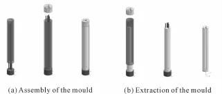
Fig.2 The process of assembIy and extraction of the mouId
The motion of petal is show in Fig.3.It can be seen that there are three parts of the structure:silicone,new cap and localizer.In the center hole of the silicone rod,a spring and a wire are connected with one side of SMA which is used to drive the petal of the flower robot,and the other side of the SMA is fixed. When the voltage is applied on the SMA,it will be constricted and take the wire downwards.In this time,the petal which connects with the other side of the wire,will be motioned downwards with the tension generated by SMA.At the same time,the petal will be constricted with the localizer.
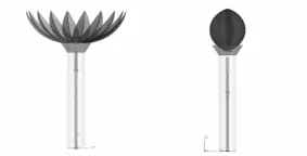
Fig.3 The motion of petaI in fIower robot
Based on the structure of stem,in the design of leafage,the SMA just need to adhere to one surface of the leafage and fix the two sides of it.The fashion of motion in leafage is the same as the stem structure,and the motion of leafage is shown in Fig.4.
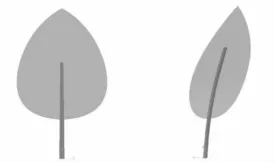
Fig.4 The motion of Ieafage in fIower robot
After the parts of flower robot such as stem,petal and leafage have been designed,the smart flower robot,whose sketch is shown in Fig.5,will be designed next
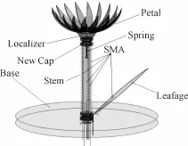
Fig.5 The structure of fIower robot
In this robot,three SMA wires are used to control the action of leafages and petals,respectively.The petals are connected to the connector of petals and assembled in the base of petals.When the SMA wire which connects to the connector is electrified,the petals will be drawn along the incline of the base of petals and close.When the current is switched off,the petals will reconvert because of the spring.For the leafage,the SMA wire also can control it to wind and unwind.Combining these parts and stem actuator,the flower robot can perform some simple actions.
3 Control system
A Kinematic Equation[18]has already been derived for the stem,and which describes the relationship of load P and displacement,and now the paper tries to determine the relationship between load P and voltages.The load here would act as a converter linking up the inputs(voltages)to the outputs(displace-ment);a fitting curve is built by correlating the voltages with the loads the fitting chart is shown in Fig.6.
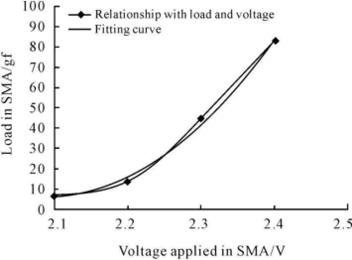
Fig.6 Fitting curve
The horizontal axis is the inputting voltages while the vertical axis displays the corresponding loads per input.From this correlation Equation(1)can be built up as follow:

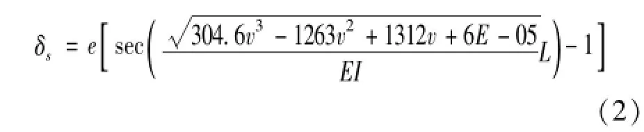
It describes the relationship between voltages and loads;P is the load of SMA,while V represents the voltages applied on the wire.By combining the Equation(1)with the equation referred in reference[18],Equation(2)can be deduced for the stem of flower robot.
In the same way,through the bending moment equation[19]and equation(1),it can also be obtained about the kinematic Equations(3)and(4)for the petal and leafage respectively.
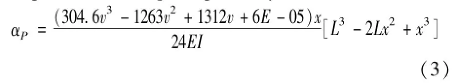
where αPis the displacement of the flower petal,x is the half length of petal about 6 mm,EI is the bending stiffness of the section,E is the young’s modulus and I is the Poisson ratio of the materials of the flower petal.
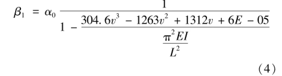
Where β1is the maximal displacement of the flower leafage,v is the voltage which is the output in the control system,EI is the bending stiffness of the section,E is the young’s modulus and I is the Poisson ratio of the materials of the flower leafage.
Fig.7 gives an overview of how the control system as an organic body works.It is strictly based on the Kinematic equations covered in earlier paragraphs,and it is maneuvered by the dSPACE system.The whole process works as follows:datum quantity is given to the control panel(automatically converted and displayed into the desired results,i.e.degree of displacement,angles in space),the control panel reads and translates the datum quantity into simulation signals through the processing of Matlab/Simulink,thus it in turn translates the input to the robot through voltages,and eventually the robot incorporates these inputs and interprets them into the desired results.
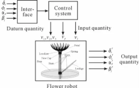
Fig.7 The process of controI system
The first step in control stage is to simulate all the input signals in Matlab/Simulink;since the movement of the stem is the most complicated part in the entire system,the mechanism behind the stem control will be elaborated first in the paper.Fig.8 illustrates briefly the flow of process in stem motion control:
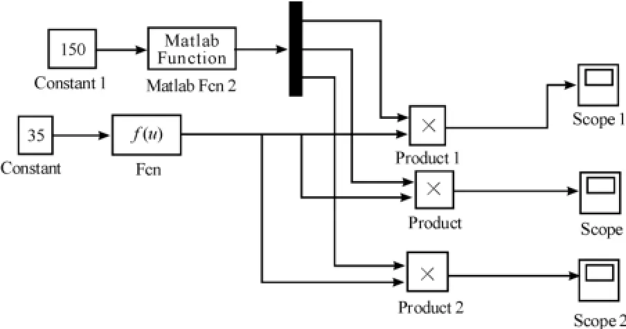
Fig.8 The simuIink in MatIab of stem
In this chart,constant 1 represents the angle inputs which extends from 0 to 360 degrees;Matlab Function works as a logic control module which analyzes the input angle and thus translates such inputs into the voltages placed on tri-SMA wires incorporated on the stem which in turn controls the movement of the stem; Product,Product 1 and Product 2 are the voltages placed on the tri-SMA wires;constant 1 is the displacement factor inputted into the stem motion,which ranges from 0 to 83;Fcn is the Kinematic Equation(18)for stem derived in earlier chapter;the Fcn function works as the core of the entire control phase as it defines the degree of displacement and turning angle in the stem movement.Scope,Scope 1,Scope 2 are the monitoring session enabling handlers to observe the actual voltages placed on each of the 3 SMA-wires.
After the elaboration of stem control,the paper will move to the control of leafage and petal.The study follows an identical procedure of simulating the movements in Matlab/Simulink and then controls the movement through dSPACE However,the flow of information is quite different.It is illustrated in Fig.9.
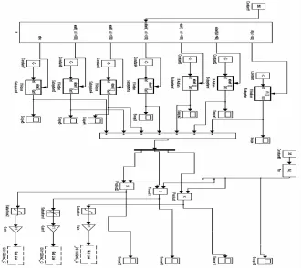
Fig.9 The controI system by dSPACE
Constant 1 is the variable for angle input,ranges from 0 to 360 degrees If the module is the logic control of directions,it is opened to 6 sets of valves with 60 degrees applied to each set of valve,i.e.the valve set which represent the degree 330 to 30 is shown in a string(1,0,0),which controls the open/close motion of the 3 voltage inputs that control the stem,where 1 means open and 0 means close.For further references degree 30 to 90 is shown as(1,1,0),and degree 90 to 150 is shown as(0,1,0);the default string for any degrees larger than 360 or less than 0 is(0,0,0).The movement direction of the stem can be accurately controlled by employing this definition.
Ds1103DAC_C5 and Ds1103DAC_C7 are output ports of the 3 voltage inputs.Constant 14 and Constant 15 are the logic control of the 2 leafages maneuvering their open and close motions;Ds1103DAC_C8 and Ds1103DAC_C9 are output ports for SMA wire voltagescontrollingtheleafage;Constant12and Ds1103DAC_C10 are logic control and SMA wire voltages for petals working in similar mechanism.
The entire system works as that we input the space angle and displacement for the stem,and the signals are interpreted to its degree of bending,direction and exact position.The same method is applied to leafage and petal as well.
4 Experiment
Due to the limitation of power output of dSPACE(its power output will dwindle even when the voltages hold),an opamp has been employed to magnify its power output in this experiment,which magnifies and enhances the electric current of outputportfor dSPACE.The equipments for the experiment are shown in Fig.10,the input DC of opamp is 5v in the system.
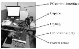
Fig.10 The equipment of experiment
The entire flow would work like this as the opamp has been added into the process:user give out inputs through PC control interface,dSPACE analyzes the inputs and translates them into voltages,the opamp magnifies the electric currents and thus electric signals,and eventually the control voltages reach the flower robot to control the motion of the robot.The results documenting the results of such control are illustrated in Fig.11 and Fig.12.
Fig.13(a),(b),(c)show the comparisons between the results of kinematic equation and experiment on stem,petal and leafage.
In Fig.13,the experimental results are very similar with those of mathematical analysis.The bending displacement is directly proportional to the input voltage. The differences of the three results are caused by the error of assumption in mathematical analysis and experimental analysis.In addition,the measurement error in experiment can be one reason of the differences.
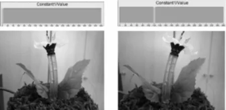
Fig.11 The movement of stem in different azimuth angIe
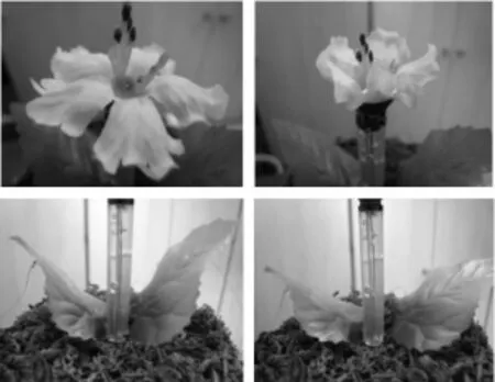
Fig.12 The movement of fIower petaI and Ieafage
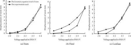
Fig.13 Compare with the resuIt of equation and experiment
5 Conclusions
In this paper,the stem,petal and leafage structures were proposed for flower robot.As an actuator for stem structure,we adopted coil type SMA was adopted,and silicone stem structures with 3 coil type SMA were proposed.Using SMA actuator,the study designed and fabricated the stem structure with 8mm of diameter and 50 mm of length.The displacement of the flower robot structure was calculated through mathematical analysis.And the control system was design by dSPACE.Finally,through the experiment of the fabricated flower robot structure,the displacements can be measured.In addition,the results from the mathematical analysis and the experiment are compared.Through the various experiments of the flower structure,its performances for robot are evaluated.
[1]Tanaka M,Furubayashi M,Tanahashi Y,etal.Development of an active palpation sensor for detecting prostatic cancer and hypertrophy[J].Smart Mater Struct,2000:878-884.
[2]Johnson A D,Martynov V,Gupta V.Applications of shape memory alloys,Advantages,disadvantages and imitations[J]. SPIE,2001(4557):341-351.
[3]Graesser E J,Cozzarelli F A.Shape-memory alloys as new materials for aseismic isolation[J].Journal of Eng,1991(3):2590.
[4]Huang W.Modified shape memory alloy(SMA)model for SMA wire based actuator design[J].Journal of Intell.Mater. Syst.Struct,2000(10):221-231.
[5]Pfeiffer C,Mavroidis C,DeLaurentis K,etal.Shape Memory Alloy Robot Prostheses:Initial Prototypes[C]//Proceedings of the 1999 Advances in Bioengineering Conference,ASME International Mechanical Engineering Congress and Exposition,Nashville,BED,1999,43:145-146.
[6]Mascaro S A,Asada H H.Wet Shape Memory Alloy Actua-tors for Active Vasculated Robotic Flesh[J].Proceeding of Robotics and Automation,2003,1:282-287.
[7]Kim B,Lee M,Lee Y,etal.An earthworm-like micro robot using shape memory alloy actuator[J].Sensors and Actuators,2006,125:429-437.
[8]Tanaka M,Chonan S.Development of an active palpation sensor for detecting prostatic cancer and hypertrophy[J].Smart Mater.Strut.,2000(9):878-884.
[9]Garner L J,Wilson L N,Rediniotis O K.Development of a shape memory alloy actuated biomimetic vehicle[J].Smart Mater.Strut.,2000(9):673-683.
[10]Gangbing Song,Brij N Agrawal.Active position control of a shape memory alloy wire actuated composite beam[J].Smart Mater.Strut.,2000(9):711-716.
[11]US Patents:US4,399,493[P].
[12]US Patents:US4,888,219[P].
[13]US Patents:US6,153,274[P].
[14]US Patents:US6,198,459[P].
[15]JP Patents:08-41716[P].
[16]www.sciencedaily.ocm/releases/2007/04/070425103027. htm[EB/OL].2007-04-07.
[17]Park H K,Park S H,Park J O.A study on the Moving Mechanism for Flower Robot[C]//International Conference on Control,Automation and Systems,2007.
[18]Hao Lei Huang,Suk-Ho Park,Jong-Oh Park.Development of stem structure for Flower Robot Using SMA Actuators[C]// Proceedings of the 2007 IEEE International Conference on Robotics and Biomimetics.
[19]Stephen H C.An introduction to the mechanics of solids[M].[S.l.]:[s.n.],1978.
基于SMA驅動結構的花型機器人設計
黃皞磊*,舒鶇鵬,羅應娜
重慶工業職業技術學院機械學院,重慶 401120
以一種花型的家用服務性機器人的結構運動為研究對象,用硅膠作為花的根部材料,并在其中采用彈簧式的記憶合金作為驅動器,以線圈式SMA作為花瓣和葉子的驅動。采用SMA驅動器,設計并制造了花型機器人構造;通過得到根部、花瓣和葉子的運動方程,由dSPACE系統設計和控制驅動了花型機器人。通過實驗證明了該系統具有可行性。
記憶合金(SMA);驅動器;花型機器人;控制系統
10.3969/j.issn.1001-3881.2015.12.026Document code:A
TP242.6
2 September 2014;revised 22 December 2014;accepted 6 March 2015
*Corresponding author:Hao-lei Huang,Master,
E-mail:eaalhuang@126.com
猜你喜歡
化學教與學(2023年5期)2023-04-03 06:12:14
廣東建材(2021年6期)2021-07-01 02:24:02
現代裝飾(2020年7期)2020-07-27 01:27:42
流行色(2020年1期)2020-04-28 11:16:38
科學技術創新(2020年21期)2020-01-06 20:58:51
中學生數理化·八年級物理人教版(2019年12期)2019-05-21 07:26:42
藝術啟蒙(2018年7期)2018-08-23 09:14:18
海峽姐妹(2017年7期)2017-07-31 19:08:17
Coco薇(2017年5期)2017-06-05 08:53:16
中國工程咨詢(2015年8期)2015-02-16 06:38:52
- 機床與液壓的其它文章
- Comparative study between the single frequency and synchronous double frequency induction hardening technique for gear
- Finite element simulation of different surface micro-pits textures cutting tool strength based on ANSYS/Workbench
- Research and optimization on the venturi tube dynamic throttling element of new flowmeter
- Study on the defects and improvement of sequential function chart
- Design of quality traceability system for a kind of electromechanical products based on OPC
- Design and simulation for the brake of crane lifting device