Finite element simulation of different surface micro-pits textures cutting tool strength based on ANSYS/Workbench
2015-12-19 08:48:38Xiao1inMAMinggangXUZhenZHANGMechanicalandElectricalEngineeringCollegeNorthChinaUniversityofTechnologyBeijing100144China
機床與液壓 2015年12期
Xiao-1in MA,Ming-gang XU,Zhen ZHANG(Mechanical and Electrical Engineering College,North China University of Technology,Beijing 100144,China)
Finite element simulation of different surface micro-pits textures cutting tool strength based on ANSYS/Workbench
Xiao-1in MA,Ming-gang XU*,Zhen ZHANG
(Mechanical and Electrical Engineering College,North China University of Technology,Beijing 100144,China)
Bionic tribologicalstudies have shown that placing micro-texture in rake face can improve the friction condition of the tool,but the placement of the micro texture will produce certain effect the strength of the structure of the cutting tool.In this paperestablish atool modelincludesmicro-pit texture,bumptextureand stripestextures,and finite element analysis is performed for the tools using ANSYS/Workbench.Analysis results indicate:in the same circumstances,micro-pits textured had a greater impact on the stress of the tool and stripetexture had a lesser impact on the stress of the tool,three kinds of texturealmost the same effect on deformation of the cutting tool. Stripe textures have little effect on the strength of the cutting tool.
Micro-texture,Finite element analysis,ANSYS,Cutting tool strength
Hydromechatronics Engineering
http://jdy.qks.cqut.edu.cn
E-mail:jdygcyw@126.com
1 Introduction
In recent years,the metal processing industrytowardefficient,energy-saving,environmentally friendly direction,but the tool wearisa majorconstraintprocessing efficiencyfactor.Modern tribology and bionics confirmed that cutting tools with high performance in the form of non-smooth surface texture(several kinds of micro texture surface topography were shown in figure 1)had better antiwear and antifriction performance[1 -2].So in addition to the performance of the material,the cutting tool abrasion anti-friction can also achieved with a range of morphology of surface texture in the cutting face.
The surface of the micro texture combined minimal quantities of lubricant technology is good for soothing infiltration,storage,film-forming medium,can achieve better antifriction and suppression of workpiece material stick to the knife,thus extending the cutting tool life[3-4].
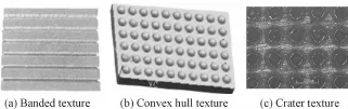
Fig.1 Three kindsofmicrotexture surface topography
The research of micro texture in the field of cutting tools is still relatively small and in its infancy.Manabu Wakuda etal.[5]had found that the existence of the pits can reduce the skin friction coefficient from 0.12 to 0.12 under the condition of lubrication.NoritakaKawasegi etal[6]machined micron and nano-scale groove texture on the tool rake face with femtosecondlasermachine,and they found the texture on the surface of the cutting tool can obviously decrease friction when cutting aluminum alloy under the condition of minimal quantities of lubricant.Furthermore the direction of the groove has a larger effect on cutting performance,micro texture in the vertical direction of the chip flow has more affection on the texture antifriction than micro texture in the parallel direction(shown as Fig.2)[7].
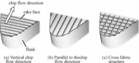
Fig.2 Texture direction
Wu Ze from Shandong University[8]machined micro texture in the carbide tool wear area using the laser processing method and filled solid lubricant MoS2. This micro-textured self-lubricating tool can significantly reduce the cutting force,decrease wear and rake bond chips to improve cutting performance.
Wang Liang etal.had studied the influence of the crater depth,spacing and diameteron the strength of the cutting tool,and found that crater diameter greater influence on the strength of the cutting tool[9].
With the progress of computer technology,finite element simulation technology is widely applied to mechanical manufacturing and the application of this technology can replace cost to a certain extent,the costs of a large number of experiments,the application of this technology can take place of the large cost experiments.The finite element simulation technology first used in cutting process simulation in the 1870 s,R.Lajczok from America[10]analyzed the cutting process with the finite element method in 1980.In 1990,Eular finite element model was used to study the orthogonal cutting by Strenkowski and Moon[11],and simulated the chip shape.They predictedthe temperature distribution in the chip,cutting tool and workpiece under the condition of ignoring elastic deformation.In recent years,the application of finite element simulation technology in the manufacturing process has also received more in-depth research. Cutting model was calculated by finite element analysis with DEFORM-2D software by Fang Gang[12]from Tsinghua University.They got the results of the chip formation,temperature distribution,the change of cutting force and residual stress,and the analysis results were coincided with the experimental results. Li Haining,Dan Chenwei et.al[13]used the finite element method to calculate the stresses of orthogonal metal cutting tool.They analyzed the negative shear is easy to cause of tool breakage,compared the shear stress distribution on the positive and negative shear. Although the micro texture can improve the cutting performance of cutting tool,but plant micro texture in the tool surface can produce certain effect on strain and stress.This paper used the ANSYS/Workbench to analyze the micro texture influence of the mechanical strength of the cutting tool and main research different texture on the deformation of cutter and the influence of stress.The result can give advice to place micro texture in the tool surface.
2 Models
Lathe tool is the most widely used metal cutting tool can process all kinds of rotating body parts,this article make finite element analysis on the typical lathe tool.This article choose carbide cylindrical lathe tool and the cutting tool geometry model is shown in Fig.3[14],geometry size of tool rod:B*H=20 mm×20 mm,L=120 mm,the cutting tool rake Angle is 0°,the clearance angle is 10°,the cutting speed is V= 2.0 m/s,the feed rate is f=0.3 mm/r,the cutting depth is ap=1.0 mm.Thecutting tool material is carbide,brand YG8,specific parameters are shown in Table 1 below.
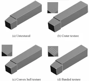
Fig.3 Different textures of tooI geometric modeIs
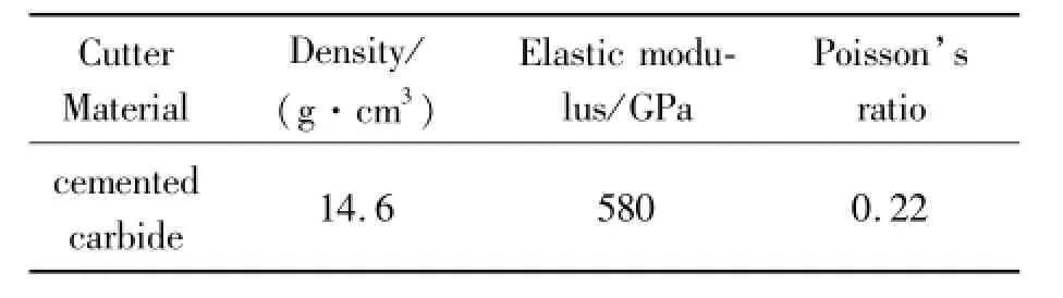
TabIe1 MateriaI parameters of YG8 cemented carbide[15]
The kinds and size of the texture have influence on the strength of the cutting tool.The crater diameter has a greater influence upon the strength of the cutting tool,and the texture has less affected when crater diameter is 70 μm[9],so choosing these different textures in the process of modeling the diameter of 70 μm.The depth of the pits and the fabric structure was 50 μm,the height of the convex hull texture was 50 μm.The texture spacing between 100 μm and 200 μm,had little effect on the strength of the cutter,in the process of modeling select the texture spacing is 200 μm.
ANSYS own adaptive meshing method was chosen to mesh the tool modelwith eight nodes hexahedron element type and the custom unit of length is 5e-5m.The lathe tool is divided into 6357 nodes,3930 units(as shown in Fig.3),and took the cutter bar and blade as a whole part in the finite element model assumes is convenient to load and calculation.

Fig.4 The finite eIement modeIs
3 The applied load and constraints
In the process of machining,the actual load on the tool is surface load,and the load applied in the process of finite element analysis can be divided into two ways.i)Choose cutting tool rake face for a certain area of applied surface loads,as shown in Fig.5(a);ii)applied load on the main cutting edge and vice cutting edge,as shown in Fig.5(b).In order to simulate the situation of stress in the process of cutting tool using two ways mentioned above to applied the loads.In the actual machining,the cutting tool and workpiece contact is only a small part.According to the cutting depth ap=1 mm and the feed rate is f= 0.3 mm/r.A linearly decreasing normal pressure from the main cutting edge is applied on the chip-tool contact area of approximately 1 mm×1 mm,resulting in an average pressure of 600 MPa which is determined based on the main cutting force.The feed force(Ff= 330 N)and thrust force(Ft=300 N)are evenly divided along the main and side cutting edge as nodal forces,respectively.The constraints were applied simulate the actual case and applied the fixed constraints in the shank.The load and constraint imposed as shown in Fig.5(c).
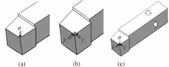
Fig.5 Load diagram
4 The simulation results
4.1 Von Misses Equivalent Stress WithDifferent Texture Micro Texture Tool
Von Mises stress is a kind of equivalent stress based on the shear strain energy:
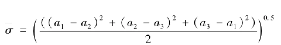
a1,a2,a3refers to the first,second and third principal stress respectively.When mechanical objects within a bit of equivalent stress reaches a certain value,the point began to enter the plastic state,and the transverse rupture strength of the cemented carbide is about 2.3 GPa.
The Von Misses equivalent stress for different textures is shown in Fig.6.As can be seen from the Fig. 7,placing texture in the tool surface texture has a certain influence on the tip of Von Misses equivalent stress.The crater texture has relatively large influence on the tool and makes the Von Misses equivalent stress increases 26.8%;stripe texture has minimal impact on the tool and makes the Von Misses equivalent stress increases 11.2%.
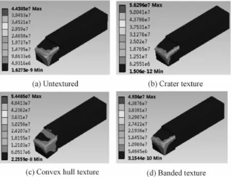
Fig.6 Different textures of tooI equivaIent
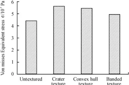
Fig.7 Von misses equivaIentstress
4.2 The deformation analysis of different textures
The cutter tool deformation model is assumed as a cantilever beam and the tool fixture fixed to support the cutting tools.The cutting forces applied on the main cutting edge and vice cutting edge make deformation on the tool in the x,y direction.
In the process of machining,the tip part of cutting tool has produced deformation,and the finite element simulation of deformation is shown in figure8.As the figure9 shown that the cutting tool placing crater texture has the largest deformation.Compared with the no texture tool its point deformation has increased 2.75% and article convex hull texture and fabric of the cutting tools its point deformation have increased 4.12% and 3.96%,respectively.In conclusion place micro texture in the cutting tool surface has an influence in its point deformation,but different types of texture have different influence on its point deformation.

Fig.8 Different textures of tooI tip deformation nephogram

Fig.9 Different textures of tooI tip deformation
5 Conclusions
In this paper,cutting tools with the three types of texture had the certain of antifriction effect and the finite element software ANSYS/Workbench was used to analyze different micro texture tool.The result shown that placing micro texture in the cutting tool surface has will produce certain effect the strength of the structure of the cutting tool.The impact of texture and texture have certain relations with the shape of the textures,and the crater texture has relatively large influence on the tool and makes the Von Misses equivalent stress increases 26.8%;stripe texture has minimal impact on the tool and makes the Von Misses equivalent stress increases 11.2%.Furthermore three kinds of textures have similar influence on deformation of the tip.As seen from the simulation results,the fabric structure texture has minimum impact on the strength of the cutting tool.
Acknowledgements
We thank everyone at Mechanical and electrical engineering college,for their invaluable assistance and advice.This research was supported in part by the Natural Science Foundation(NO.51205005).
[1]HAN Zhong-ling,WANG Jia-dao,CHEN Da-rong.Drag Reduction by Dimples on Surfaces in Plane-planeContactLubrication[J].Tribology.2009,29(1):10-16.
[2]Wang Xiao-lei,Wang Jing-qiu,Han Wen-fei.Effect of Surface Texture on Friction Reduction under Boundary Lubrication[J].LUBRICATION ENGENEERING.2007,32(12):36-39.
[3]WANG Jia-dao,CHEN Da-rong,KONG Xian-mei.Study on Lubrication of Regular Concave Surface[J].Tribology,2003,23(1):52-55.
[4]TANG Liping,LIU Ying.Influence of surface micro-texture on the tribological properties of heavy-duty gears[J].J T sing hua Un iv(Sci&Tech),2010,50(7):1009-1012,1017.
[5]Kawasegi N,Sugimori H,Morimoto H,etal.Development of cutting tools with microscale and nano scale textures to improve frictional behavior[J].Precision Engineering,2009,33(3):248-254.
[6]Sugihara T,Enomoto T.Development of acutting tool with a nano/micro-textured surface Improvement of anti-adhesive effect by considering the texture patterns[J].Precision Engineering.2009,33(4):425-429.
[7]Qi Baoyun,Li Liang,He Ning,etal.Application of Surface Texture in Tool Antifriction Technology[J].tool Engineering.2010,44(12):3-6.
[8]Wu Ze,Deng Jianxin,Qi Ting,etal.Study on Cutting Performance with Mocro-texturing Self-lubricated Tools[J]. Tool Engineering,2011,45(7):18-22.
[9]Wang Liang,Li Liang,Qi Baoyun.Finite Element Simulation of Surface Micro-pits Texture Cutting Tool Structure Strength[J].Tool Engineering,2011,45(9):12-15.
[10]Lajczok M R.A Study of Some Aspects of Metal Cutting By the Finite Element Method[D].NC State University,1980,1-20.
[11]Strenkowski J S,Moon K-J.Finite element prediction of chip geometry and tool/workpiece temperature distribution in orthogonal metal cutting[J].Transaction of ASME Journal of Engineering Industry,1990,127:313-318.
[12]FANG Gang,ZENG Pan.FEM Simulation of Orthogonal Metal Cutting Process[J].MECHANICAL SCIENCE AND TECHNOLOGY,2003,22(4):641-645.
[13]LIHaiOning,SHAN ChenOwei,LIN X iaoOjun.Analyzing Stresses ofOrthogonalMetalCuttingToolbyFEM[J].Aeronautical Computing Technique,2008,38(1):16-18.
[14]Wang Najun.Design of metal cutting tools guide book[M].Harbin:Harbin Industrial University Press,2000.
[15]Mechanical design manual 6 editorial board.Mechanical design manual[M].Beijing:Chemical Industry Press.
基于ANSYS/Workbench不同微織構刀具強度有限元分析
馬小林,徐明剛*,張 振
北方工業大學機電工程學院,北京 100144
仿生摩擦學研究表明在刀具表面置入微織構紋理可以改善外圓車刀在切削時的摩擦狀況,但是置入的微織構紋理會對刀具的結構強度產生一定的影響。針對微坑織構、凸包織構和條紋織構紋理進行了刀具的建模并利用ANSYS/Workbench對不同微織構紋理刀具進行有限元分析。結果表明:在微織構的深度、間距尺寸一致的情況下,微坑織構紋理對刀具的應力影響程度較大,條紋織構紋理的影響程度較小,3種織構紋理對刀具的變形影響相差不大,綜合比較條紋織構對刀具強度影響較小。
微織構;有限元分析;ANSYS;刀具強度
10.3969/j.issn.1001-3881.2015.12.013Document code:A
TH114
11 November 2014;revised 5 January 2015;accepted 5 March 2015
*Corresponding author:Ming-gang XU,Professor.
E-mail:xmg@mail.tsinghua.edu.cn
猜你喜歡
中學生數理化·八年級物理人教版(2022年3期)2022-03-16 05:55:08
當代陜西(2021年2期)2021-03-29 07:41:24
民用飛機設計與研究(2020年4期)2021-01-21 09:15:02
電子制作(2018年18期)2018-11-14 01:48:24
山東工業技術(2016年15期)2016-12-01 05:31:22
中國塑料(2016年3期)2016-06-15 20:30:00
機械工程師(2015年10期)2015-02-02 01:14:03
機電產品開發與創新(2014年4期)2014-03-11 16:42:24
上海金屬(2013年4期)2013-12-20 07:57:18
船海工程(2013年6期)2013-03-11 18:57:27
- 機床與液壓的其它文章
- Comparative study between the single frequency and synchronous double frequency induction hardening technique for gear
- Design of SMA actuator of stem structure for flower robot
- Research and optimization on the venturi tube dynamic throttling element of new flowmeter
- Study on the defects and improvement of sequential function chart
- Design of quality traceability system for a kind of electromechanical products based on OPC
- Design and simulation for the brake of crane lifting device