Kinematic Calibration of Asymmetricly Actuated 6-DOF 3-PPPS Parallel Mechanism
2016-09-05 08:56:44ChenLeiHuangXiangMaZhiqiangLiShuanggao
Chen Lei, Huang Xiang, Ma Zhiqiang, Li Shuanggao
1.College of Mechanical and Electrical Engineering, Nanjing University ofAeronautics and Astronautics, Nanjing 210016, P.R. China;2.Institute of Aeronautical Manufacturing Technology Research,Shanghai Aircraft Manufacturing Co., Ltd, Shanghai 200436, P.R. China
(Received 27 October 2015; revised 11 April 2016; accepted 18 April 2016)
Kinematic Calibration of Asymmetricly Actuated 6-DOF 3-PPPS Parallel Mechanism
Chen Lei1,2, Huang Xiang1*, Ma Zhiqiang1, Li Shuanggao1
1.College of Mechanical and Electrical Engineering, Nanjing University ofAeronautics and Astronautics, Nanjing 210016, P.R. China;2.Institute of Aeronautical Manufacturing Technology Research,Shanghai Aircraft Manufacturing Co., Ltd, Shanghai 200436, P.R. China
(Received 27 October 2015; revised 11 April 2016; accepted 18 April 2016)
An asymmetric actuated 3-PPPS parallel mechanism was analyzed in its application to an aircraft wing adjustment process. The posture alignment precision at the wing ends was enhanced with a kinematic calibration method. A constraint equation was built based on a constraint condition that distances among spherical joints of the mechanism were constant, and further eight groups of analytic forward solutions of all poses of the mechanism were solved. An inverse equation of the posture alignment displacements of aircraft wing parts was built based on space vector chains, and a mapping equation of the pose and geometric errors of the posture alignment mechanism containing 39 error sources was derived by differentiating the kinematic equation of the mechanism. After kinematic calibration experiments, the maximum position error of the posture alignment platform dropped from 2.67 mm to 0.82 mm, the maximum angle error decreased from 0.481° to 0.167°, and the posture alignment precision of the aircraft wing end was improved.
aircraft wing adjustment; parallel mechanism; forward numerical solution; laser tracker; kinematic calibration
0 Introduction
In a modern aircraft assembling process, the digital flexible automatic assembly system[1]is gradually utilized, which mainly consists of a mechanic positioning system, a control system, a measurement system and computer software. The posture alignment precision is of significant importance for the aircraft assembly quality. However, in actual circumstances, such factors as existences of errors that occur in the processing, manufacturing, assembling processes, as well as spherical joint gaps, impose a significant effect on the aircraft assembly precision and lead to a low posture alignment precision. In this paper, a method of approaching the theoretical pose step by step was applied to the posture alignment process. After a theoretical pose was determined, each positioner actuated a certain displacement, the actual pose of the aircraft wing was measured by a laser tracker, then a pose difference value was calculated by comparing the theoretical poses with the actual ones, then each positioner was again actuated to align the posture. The whole process gained a relatively low efficiency.
There are two categories of calibration methods for any commonly used parallel mechanism, i.e., external calibration and self calibration[2-3]. External calibration is a method of using additional high-precision measurement devices to measure part or all of the pose information at the wing end. Zhuang measured its actuating displacements and poses of the Steward mechanism with a theodolite and built a function between the theoretical errors and actual measurement errors of the actuating lever and finished a kinematic calibration of the Stewart platform[4]. Gao did similar work with a laser tracker[5]. Renaud built a simple parallel calibration system with an optical visual measurement system. Self calibration is a kind of calibration which calibrates a mechanism via such sensors set inside the mechanism as measure the hinge variables[6].Wang used a process hole with certain radius on the upper platform calibration a 6-TPS parallel platform milling[7]. Zhu studied the relationship between error sources and position and pose adjustment errors by means of differential change homogeneous transform[8].
The forward solution of a parallel mechanism is mainly classified into a numerical solution and an analytic solution according to its form. In studying the quasi-3-PPPS platform, Behi firstly proposed a kind of 3-PRPS parallel mechanism[9]; Shim, Cho et al. analyzed forward and inverse kinematics, working space and dynamic operating characteristics of 3-PPSP[10-11]. Whee et al. put forward a kinematic analysis method on 3-PPSP parallel mechanism and also studied its kinematic and dynamic properties[12].
Chen[13]defined the end pose uncertainty in the numerical alignment and marry-up system of aircraft large parts, and also analyzed the effects on pose accuracy from different kinds of error sources in the measurement system by applying an interval analysis method.
As seen from above, for a currently used multi-positioner digital assembly system, available research papers analyzed error factors that affect the posture alignment accuracy and found that the corresponding error compensation methods often focused on compensating a single positioner and it was hard to identify the structural error sources in the posture alignment system and thus the compensation efficiency was not high. In this paper, data was measured by a laser tracker and the structural error sources were identified by an error calibration method based on the forward kinematics, and the posture alignment precision was increased through error compensations. Moreover, kinematic calibration was further accomplished in the posture alignment simulation system of an aircraft wing.
1 Mechanism Description
The posture alignment system of an aircraft wing is shown in Fig. 1, which mainly consists of three three-axis positioners, wing parts and the control systems. Each positioner, which is powered by a servo motor to provide a linear actuating displacement, may at most provide three degrees of freedom (DOF). The three positioners are all installed on a fixed platform at the same time and each is connected to the wing that will be adjusted by a spherical joint. The controller actuates each positioner according to the posture alignment algorithm and accomplishes the aircraft wing adjustment by changing the displacement of the actuating lever. The posture alignment system on the whole can be regarded as a 3-PPPS parallel mechanism. According to the Kutzbach-Gruler equation, the component number of the mechanism n=11,the kinematic pair number g=12, of which the relative DOF of a sliding pair is 1 and the relative DOF of a spherical joint pair is 3. The DOF of the posture alignment system of the aircraft wing F is
(1)
A global coordinate system {Og} is built with the coordinate axis being the same direction of the theoretical actuating shaft of the positioner. For the moving coordinate system {Ow} of an aircraft wing part, the location is determined by the posture alignment reference point on the aircraft wing and the vector of its origin in the global coordinate system is p.

Fig.1 Posture alignment system of an aircraft wing
1.1Inverse kinematics

where c=cos, s=sin, thus the vector of the center of technological spherical joint in the reference coordinate system of the positioner can be expressed as
(2)
and the inverse solution of the displacement of the No.j actuating shaft of the No.i positioner is expressed as
(3)
1.2Forward kinematics
The single vector chain of the posture alignment system is shown in Fig. 2. Based on the structural characteristics, the forward kinematics in a close-loop form of 3-PPPS can be obtained by the following two steps.
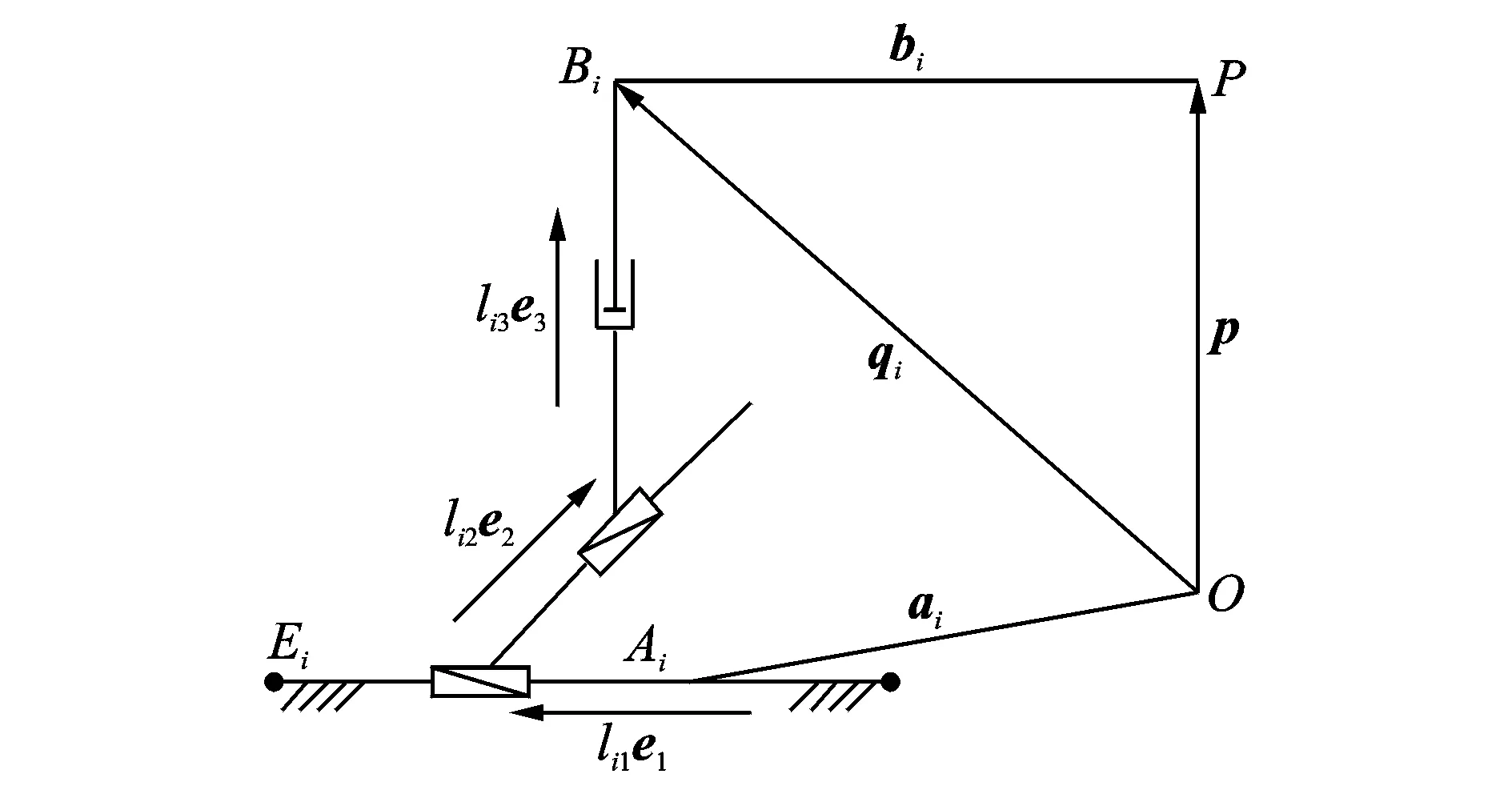
Fig.2 Single branch vector link of posture alignment system
Step 1Solve the position vector qiof the spherical joint in the fixed coordinate system, which requires the solutions of l21, l31, l32, i.e., displacements of three servo-type linear pairs.
Step 2Derive the position and pose of the moving platform from the calculated coordinates of the spherical joint.
From Fig. 2, the internal coordinates of the spherical joint in the fixed coordinate system is
In the posture alignment process of an aircraft wing, the distances between centers of spherical joints remain a constant, and the distances between spherical joints are expressed by the displacements of actuating shafts, so the displacement constraint equation of the mechanism is
By expanding the above equation, three equations of l21, l31, l32can be obtained and solved.
After the position vector qiof the technological spherical joint in the fixed coordinate system is obtained, the position vector P of the aircraft wing can be obtained.
(4)
Considering the structural characteristics of 3-PPPS, the positive directions of the x axis and z axis of the moving coordinate system can be obtained as
(5)
(6)
(7)
(8)
From Eqs.(7), (8), the altitude angles α, β and γ of the aircraft wing can be reversely solved as
(9)
(10)
(11)
Eqs.(4), (9), (10) and (11) represent the theoretical pose of the aircraft wing obtained by a method of a closed forward kinematics respectively when the actuating quantity of the positioner is determined.
2 Error Modeling and Calibration Algorithm
Error modeling constitutes a foundation of the structural calibration.A single three-axis positioner can realize moving along x,y,z directions respectively. For a single positioner branch i, presuming that there is an active actuation along three directions, respectively, the following kinematic relation exists as
(12)
where ei1, ei2and ei3are respectively the unit vector along the direction of each moving axis of the ith branch of the posture alignment system of an aircraft wing under a desirable moving circumstance. Part processing and assembly operations, position deviations of the technological spherical joints and other error factors lead to the difference between structural parameters and actual parameters in the design process. By differentiating both ends of the above equation simultaneously, the error model of the mechanism can be obtained[14-15]as
(13)

(14)
The posture alignment system may use at most nine actuation to form a redundant posture alignment. For a posture alignment system with servo displacements, six actuations is selected according to the 3-2-1 selection principle, and the remaining three moving pairs move in a servo manner, which means that the servo moving mechanism poses no restriction on the DOF of the end posture alignment and no effect on the final posture alignment precision. The kinematic relation for two branches with active actuation is
(15)
The kinematic relation of the branch with single actuation is
(16)
By differential perturbing Eqs.(15), (16) in a similar way, the forward solution model of the errors of the posture alignment system of an aircraft wing can be calculated as
(17)
After the calibration pose is chosen in the working space of the posture alignment system, as the error transmission matrix of the posture alignment platform is non-singular, then Eq.(17) is rewritten as
(18)

Then the generalized least square solution of δp can be expressed as
(19)
In order to make the calculation results get closer to the real values, and taking the singularity of the error transmission matrix Jpinto account, the least square iteration method is adopted to make identifications and the iterative step-length of the kth step is
(20)
where u is adopted to avoid the problem of any matrix singularity. Δlxmeans the gap between the actually measured actuating displacement and the theoretically calculated displacement of the k th step. Substituting the correction value of pk+1=pk+Δpkof the kth step structural parameter into the iteration equation, when ‖Δlk‖≤ε, the iteration stops.
3 Calibration Results
The simulation posture alignment system of an aircraft wing is shown in Fig. 3.

Fig.3 Experiment of posture alignment simulation
Firstly the original position of the auxiliary measurement point and spherical joint was measured, then after the positioner moved a theoretical displacement, the actual position of the auxiliary measurement point of the positioner was captured by the laser tracker.
After the positioner moved 40 mm in a moving order of li(i=1,2,…,6), another 40 mm moving along each axis was finished orderly. The total displacement was the actual displacement lmof the positioner along each axis. During the respective displacement measurement, the positions of the target joints on three auxiliary measurement levers in the measurement coordinate system were also measured. The above 12 measured poses were selected, and actual measured poses that correspond to each displacement actuation and theoretical poses that correspond to the theoretical actuating displacements lcwere calculated. The original iteration parameters of the structural parameter errors were all set 0. After the measurement values of auxiliary measurement points were obtained, actual poses and theoretically calculated poses of an aircraft part in the simulation system could be calculated to verify data obtained from calibration experimental results.
Actual unit direction of each axis was shown in Table 1.
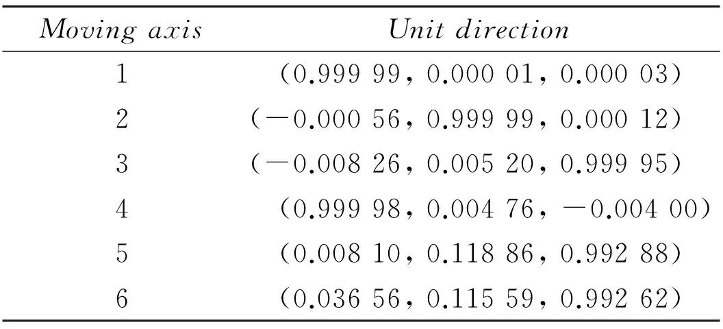
Table 1 Unit direction of active moving axis
Structural parameter errors after calibration were shown in Table 2. From Tables 1, 2, due to the existence of installment errors, there are perpendicularity deviations between each positioner axis. The positioner adopted high-precision linear guide rails and ball screws in the x and y directions, so the linearity deviations of the guide rails were relatively smaller; while in the z direction, the positioner adopted a turbine worm reducer, thus comparing with that of x and y directions, the linearity deviation is relatively larger. It could be inferred from the parameter identification results that the main error sources of the posturealignment system are attributed to the perpendicularity deviation of the positioner axis during the installment process, the calibration error of the original

Table 2 Identified structural parameter errors
Positions of the spherical joints, and the measurement deviation of the starting point on the auxiliary measurement lever, among which, the latter two error sources contributed a relatively larger share. Thus, it is necessary to impose a higher precision requirement on the shape of the spherical joints and the original position calibration. The theoretical poses of 12 groups of measurement points are calculated, such theoretical poses are input into the structural error calibration program, the error compensations are made[16], and the change of ‖δθ‖ and ‖δp‖ i.e., the angle-position comprehensive precision of each point after compensations are shown in Figs. 4,5.
As seen in Figs.4, 5, through kinematic calibration, the maximum error of the position precision of the posture alignment system of an air-craft wing drops from 2.68 mm to 0.82 mm, an increase by 65%, and the maximum angle error drops from 0.481° to 0.167°. Thus the overall precision of the posture alignment system is improved.

Fig.4 Position error before and after calibration
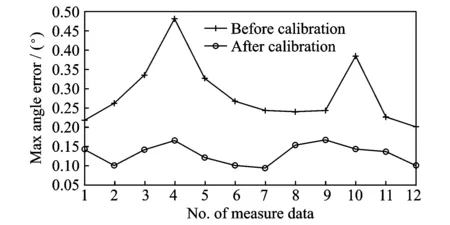
Fig.5 Angle error before and after calibration
4 Conclusions
(1) Based on the structural characteristics of a 3-PPPS servo-type parallel mechanism for posture alignment of an aircraft wing, a two-step method was applied to simplify six equation sets with six variables into three equation sets with three unknown variables, and by solving the three equation sets, the positions of eight groups of spherical joints in the fixed coordinate system were determined.
(2) By differential perturbing the motion displacement equation, an error mapping model containing 39 error sources which had definite physical meaning respectively was established
(3) By using a single Leica AT901-MR laser tracker, 12 groups of calibration pose data were measured.After calibration, the maximum error of the positioner position precision dropped from 2.68 mm to 0.82 mm, and the maximum angle error decreased from 0.481° to 0.167°, respectively, which verifies the effectiveness and feasibility of the calibration method.
Acknowledgements
This work was supported by the National Natural Science Foundation of China (No.51275234) and the Aeronautical Science Foundation of China (No.20131652027).
[1]WILLIAMS G, CHALUPA E, RAHHAL S. Automated positioning and alignment systems[R]. SAE Technical Paper, 2000.
[2]DANIEL G, EDUARDO C G, JOAQUIN B G. An overview of kinematic and calibration models using internal/external sensors or constraints to improve the behavior of spatial parallel mechanisms[J].Sensors,2013,13:10430-10448.
[3]MERLET J P. Parallel robots[M]. 2nd Ed. [S.l.]: Springer,2006.
[4]ZHUANG H, YAN J, MASORY O. Calibration of Stewart platforms and other parallel manipulators by minimizing inverse kinematic residuals[J]. Journal of Robotic Systems, 1998, 15(7): 395-405.
[5]GAO M, LI T M, WENSHENG Y. Calibration method and experiment of Stewart platform using a laser tracker[C]∥Systems, Man and Cybernetics, 2003, IEEE International Conference on. [S.l.]: IEEE, 2003, 3: 2797-2802.
[6]RENAUD P, ANDREFF N, LAVEST J M, et al. Simplifying the kinematic calibration of parallel mechanisms using vision-based metrology[J].IEEE Transactions on Robotics, 2006, 22(1): 12-22.
[7]WANG R. Calibration method of structural parameters for 6-TPS parallel platform milling[J].Journal of Nanjing University of Aeronautics & Astronautics,2009,41(6):720-726. (in Chinese)
[8]ZHU Y G, HUANG X, FANG W ,et al. Fuselage automatic position and pose adjustment method and its error analysis[J]. Journal of Nanjing University of Aeronautics & Astronautics, 2011,43(2):229-234. (in Chinese)
[9]BEHI F. Kinematics analysis for a six degree of freedom 3-PRPS parallel mechanism[J]. IEEE Journal of Robotics and Automation,1988,4(5):561-565.
[10]SHIM J H, KWON D S. Kinematics analysis and design of a six DOF 3-PRPS parallel manipulator[J].Robotica,1999,17:269281.
[11]BYUN Y K, CHO H S. Analysis of a novel six degree-of-freedom 3-PPSP parallel manipulator[J]. Journal of Robotics Research,1997,16(6):612-618.
[12]WHEE K K, YONG K B, HYUNG S C. Closed-form forward-position solution for a 6-DOF 3-PPSP parallel mechanism and its implementation[J].The International Journal of Robotics Research,2001,20(1):85-99.
[13]CHEN Z H, DU F Z, TANG X Q. Research on uncertainty in measurement assisted alignment in aircraft assembly[J]. Chinese Journal of Aeronautics, 2013, 26(6): 1568-1576.
[14]VERNER M, XI F, MECHEFSKE C. Optimal calibration of parallel kinematic machines[J]. Journal of Mechanical Design, 2005, 127(1): 62-69.
[15]MERLET J P. Jacobian, manipulability, condition number, and accuracy of parallel robots[J]. Journal of Mechanical Design, 2006, 128(1): 199-206.
[16]OIWA T. Error compensation system for joints, links and machine frame of parallel kinematics machines[J].The International Journal of Robotics Research, 2005, 24(12): 1087-1102.
Mr. Chen Lei is a Ph.D. candidate in Nanjing University of Aeronautics and Astronautics (NUAA). His major research interest is aircraft digital assembly technology.
Dr. Huang Xiang is a professor of College of Mechanical and Electrical Engineering at NUAA. His research interests include aircraft digital assembly technology and equipment, quality control of aircraft manufacturing.
Mr. Ma Zhiqiang is currently a M.Sc. candidate of NUAA. His major research interests are aircraft digital assembly technology and calibration of parallel equipment.
Dr. Li Shuanggao is an associate professor of College of Mechanical and Electrical Engineering at NUAA. His research interest lies in aircraft digital assembly technology and equipment, CAE of sheet metal forming.
(Executive Editor: Zhang Tong)
, E-mail address: xhuang@nuaa.edu.cn.
How to cite this article: Chen Lei, Huang Xiang, Ma Zhiqiang, et al. Kinematic calibration of asymmetricly actuated 6-DOF 3-PPPS parallel mechanism[J]. Trans. Nanjing Univ. Aero. Astro., 2016,33(3):294-300.
http://dx.doi.org/10.16356/j.1005-1120.2016.03.294
V262.4Document code:AArticle ID:1005-1120(2016)03-0294-07
 Transactions of Nanjing University of Aeronautics and Astronautics2016年3期
- Transactions of Nanjing University of Aeronautics and Astronautics的其它文章
- Behavior of Corrosion-Repaired Concrete Beams Reinforced by Epoxy Mortar
- Model Updating for High Speed Aircraft in Thermal Environment Using Adaptive Weighted-Sum Methods
- Removing Random-Valued Impulse Noises by a Two-Staged Nonlinear Filtering Method
- Robust Fault-Tolerant Control for Longitudinal Dynamics of Aircraft with Input Saturation
- Numerical Calculations of Aerodynamic and Acoustic Characteristicsfor Scissor Tail-Rotor in Forward Flight
- DNS Study on Volume Vorticity Increase inBoundary Layer Transition