Numerical Calculations of Aerodynamic and Acoustic Characteristicsfor Scissor Tail-Rotor in Forward Flight
2016-09-06 01:01:03FanFengHuangShuilinLinYongfeng
Fan Feng, Huang Shuilin, Lin Yongfeng
China Helicopter Research and Development Institute, Aviation Industry Corporation of China,Jingdezhen 333000, P.R.China
(Received 22 December 2014; revised 12 March 2015; accepted 19 March 2015)
Numerical Calculations of Aerodynamic and Acoustic Characteristicsfor Scissor Tail-Rotor in Forward Flight
Fan Feng*, Huang Shuilin, Lin Yongfeng
China Helicopter Research and Development Institute, Aviation Industry Corporation of China,Jingdezhen 333000, P.R.China
(Received 22 December 2014; revised 12 March 2015; accepted 19 March 2015)
The aerodynamic and aeroacoustic characteristics of a scissor tail-rotor in a forward flight are numerically calculated. A novel computational fluid dynamics (CFD) model based on Navier-Stokes (N-S) equations is presented to simulate the unsteady flowfield and the aerodynamic characteristics of a scissor tail-rotor in the forward flight. Then the Farassat Formulation 1A derived from the FW-H equation is coupled into the CFD model in order to compute the aeroacoustic characteristics of the scissor tail-rotor. In addition, two different scissor tail-rotor configurations, i.e., the L- and U-configuration, are analyzed in details and compared with a conventional one. The influence of scissor angles on the aerodynamic and aeroacoustic characteristics of the scissor tail-rotor is also investigated. The simulation results demonstrate that the flowfield, aerodynamic force and aeroacoustic characteristics of a scissor tail-rotor are significantly different from the conventional one, and the aerodynamic interaction decreases with the increase of scissor angle, which leads to a reduction of amplitude variation of the tail-rotor thrust in the forward flight. The scissor angle has an important effect on the aerodynamics and aeroacoustics of the scissor tail-rotor.
computational fluid dynamics (CFD); scissor tail-rotors; aerodynamic characteristics; aeroacoustic characteristics; Navier-Stokes (N-S) equations
0 Introduction
The scissor tail-rotor has an unconventional configuration, and it is mainly employed on modern armed helicopters such as the AH-64 Apache and the Mi-28 Havoc. A typical feature of scissor tail-rotors is the uneven blade azimuthal spacing for both the upper and lower pairs of blades. Previous research demonstrated that scissor tail-rotors had certain advantages in noise reduction when compared with the conventional ones. However, only a limited amount of work has been carried out on the scissor configurations and the majority of researchers focused on the conventional helicopter tail-rotors with an equal azimuthal spacing. Therefore, it is essential to investigate the aerodynamic and aeroacoutistic of scissor tail rotor configurations for its design application.
So far, most of the research has been focused on the scissor tail-rotors in a hover condition, and only few studies were associated with forward flight condition. Unfortunately, some conclusions led by different researchers were contradictory. For example, Sonneborn et al.[1]conducted an experiment on the scissor rotor in 1974, and his results indicated that the scissor rotor had no advantages in aerodynamics and acoustics when compared with the conventional one. Rozhdestvensky[2]carried out a new experiment on the hover performance of scissor tail-rotor in 1996, and compared the noise level of Mi-28 helicopter equipped with both a conventional tail-rotor and a scissor one. However, results in Ref. [2] were quite different from Sonneborn′s, which indicated that the scissor configuration was superior to the conventional one in aerodynamic and aeroacoustic characteristics. The differences between the studies of Sonneborn and Rozhdestvensky were thought to be due to the higher rotational speed of Rozhdestvensky′s rotor model. In 2007, the noise and induced velocity of a scissor rotor was measured by experiments conducted in the Nanjing University of Aeronautics and Astronautics[3], and the hover performance for the test rotor using a free-wake method[4]was also numerically calculated. The experimental and computational results demonstrated that the configuration parameters had an important effect on both aerodynamics and aeroacoustics of scissor rotors. In Ref. [5], the aerodynamic and aeroacoustic characteristics of scissor tail-rotors in hovering were discussed, but those in a forward flight have not been addressed.
Different from most of the previous research which were mainly focused on hover conditions, this paper aims to conduct numerical studies on both the aerodynamic and aeroacoustic characteristics of the scissor tail-rotors in a forward flight, which is more difficult to investigate when compared with that in hover due to unsteady flow. In addition, the effect of the configuration parameters of scissor tail-rotors is also investigated.
1 Computational Methodology and Validation
1.1Aerodynamic model
A CFD computational model is adopted to simulate the unsteady flowfield of scissor tail-rotors in the forward flight. The three-dimensional (3D) unsteady Reynolds-average Navier-Stokes (RANS) equations are employed as the governing equations, which can be written aswhere W is the vector of conserved variables. F(W) and G(W) are the convective (inviscid) and the viscous flux vectors, respectively.
(1)
In the current CFD solver, a third-order upwind scheme (Roe scheme)[6]is used to calculate the convective fluxes on the faces of the control volume. For the time integration, a dual-time stepping method is applied to simulate the unsteady flow phenomenon, together with the LU-SGS scheme[7]at every pseudo-time step. The Spalart-Allmaras one equation model[8]is used as the turbulent model, which is uncoupled with the flow governing equations.
A moving overset-grid system is used to deal with the rotation and the pitch motion of the tail-rotor blades in the forward flight, which is different from the overset-grid system used in hover. In a grid system, a C-O type grid is used for the body-fitted blade grid (the near grid) and a Cartesian type is adopted as the background grid, respectively. The topological relationship between the blade near-body grid and the background grid is established using the hole cutting and donor cell identifying process, and the flowfiled data between the two set of grids are exchanged using a high-order interpolation scheme.
1.2Acoustic model

(2)
(3)
1.3Computational results and validations
Due to the lack of available tail-rotor experimental data in the forward flight, the benchmark case for the Lynx tail rotor in a hover condition[10]is selected to validate the current CFD code for aerodynamic predictions. The advance ratio can be set to zero in the current CFD code to simulate the flowfiled in hover. Fig.1 compares the CFD predicted thrust and torque coefficients of the tail-rotor with the corresponding experimental data[10]. The excellent correlation between calculation and measurements validates the capability of the CFD analysis.
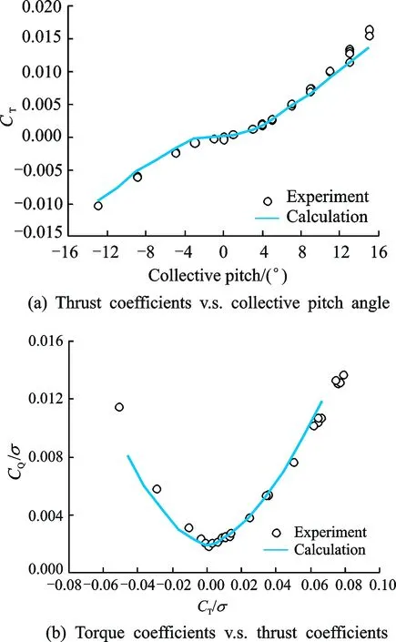
Fig.1 Comparison of hover performance between CFD and experimental results for the Lynx tail-rotor
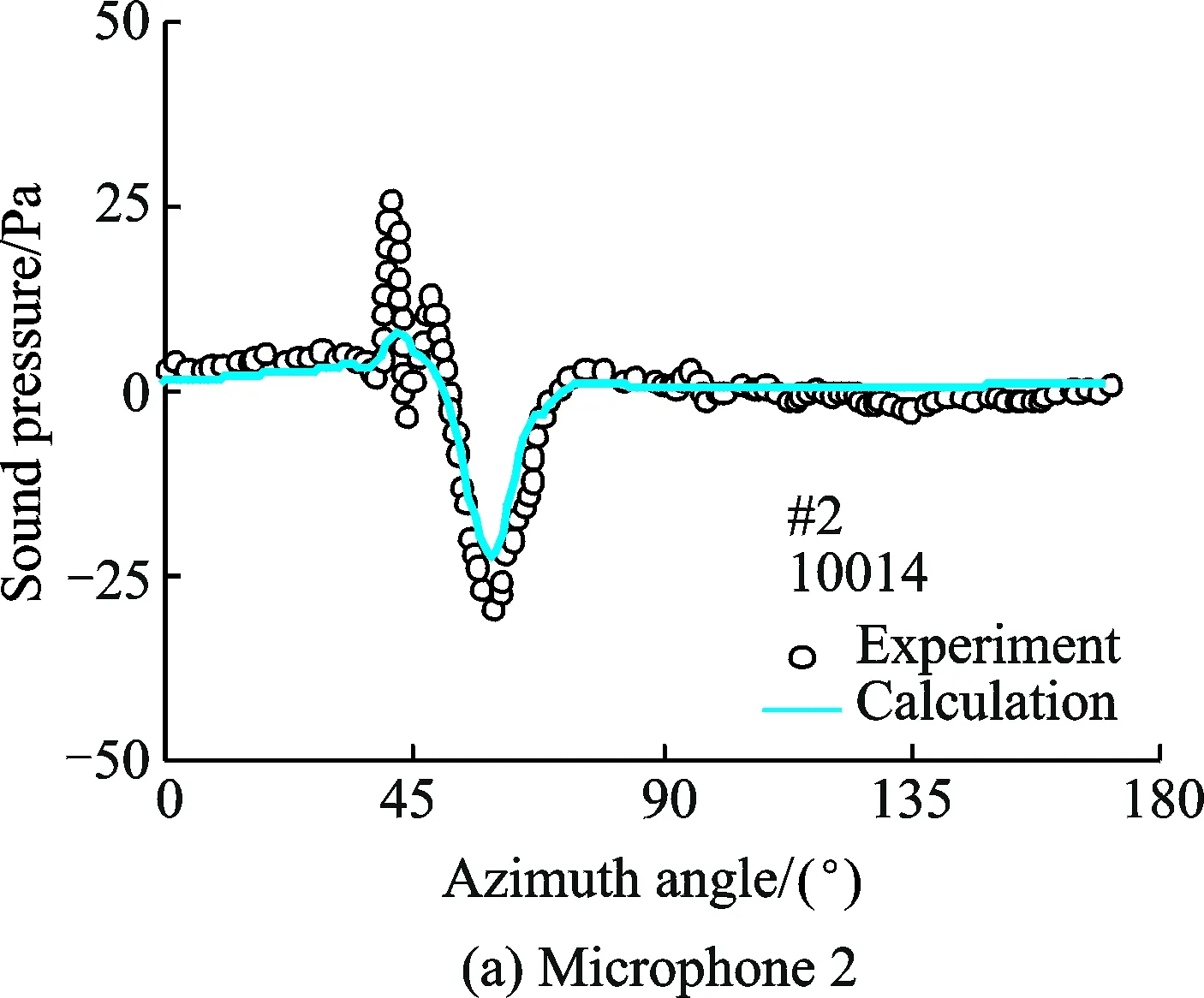
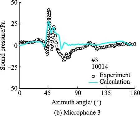
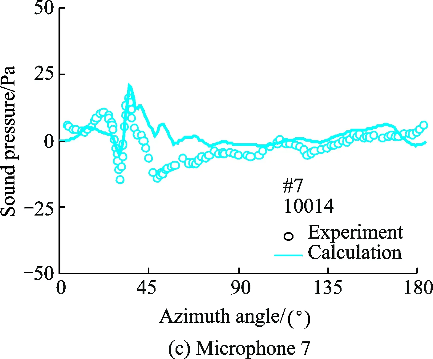

Fig.2 Comparison of predicted and measured time histories of sound pressure for the AH-1/OLS rotor in hover
To validate the current acoustic model, the noise level of AH-1/OLS rotor[11]is calculated and compared with the available experimental data in Ref.[11]. A blade vortex interaction(BVI) test condition (No.10014) is selected as a numerical benchmark, and the results are shown in Fig. 2. The comparison between the calculated results and experimental data demonstrated that, the present method can predict the representative characteristics of BVI acoustics effectively except for some discrepancies in the detailed magnitude. As shown, the correlations between the CFD simulation and the measurements also demonstrate the capability of the current CFD solver for the complex BVI flowfield, which is important for the analysis of interferences among scissor tail-rotor blades. However, the calculated results, which may be affected by the grid quality and numerical oscillation, do not consist very well with the experimental data at some microphones.
2 Results and Discussions
The tail-rotor model used in Rozhdestven-sky′s experiment was selected as a benchmark numerical example in the current study of scissor tail rotors in the forward flight. The detailed rotor model parameters can be found in Ref. [2]. As mentioned in Ref. [2], there are two types of configurations for a scissor tail-rotor, that is, the L- and U-configuration. In the L-configuration, the leading blade is lower than the following one, while in the U-configuration, the leading blade is higher than the following one. For convenience, the leading blade is further defined as blade 1, and the following blade is defined as blade 2. According to the definition, blade L-1 represents the leading blade in the L-configuration. Similarly, the other blades can be defined, as shown in Fig.3.

Fig.3 Schematic illustration of different configurations for a scissor tail-rotor
Here the vertical space of the scissor tail-rotor is fixed at a constant value ofΔh/R=0.1, where R represents the tail-rotor radius. The overset grid system used for scissor tail-rotor flow field simulation is shown in Fig.4.
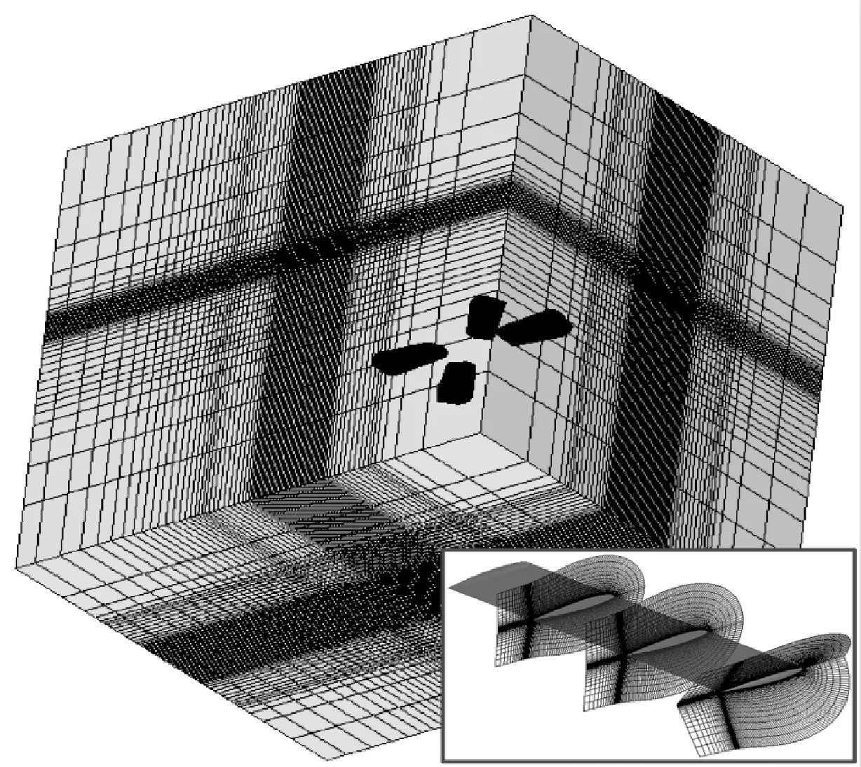
Fig.4 Schematic of grid system for scissor tail-rotor in forward flight
2.1Flow field characteristics
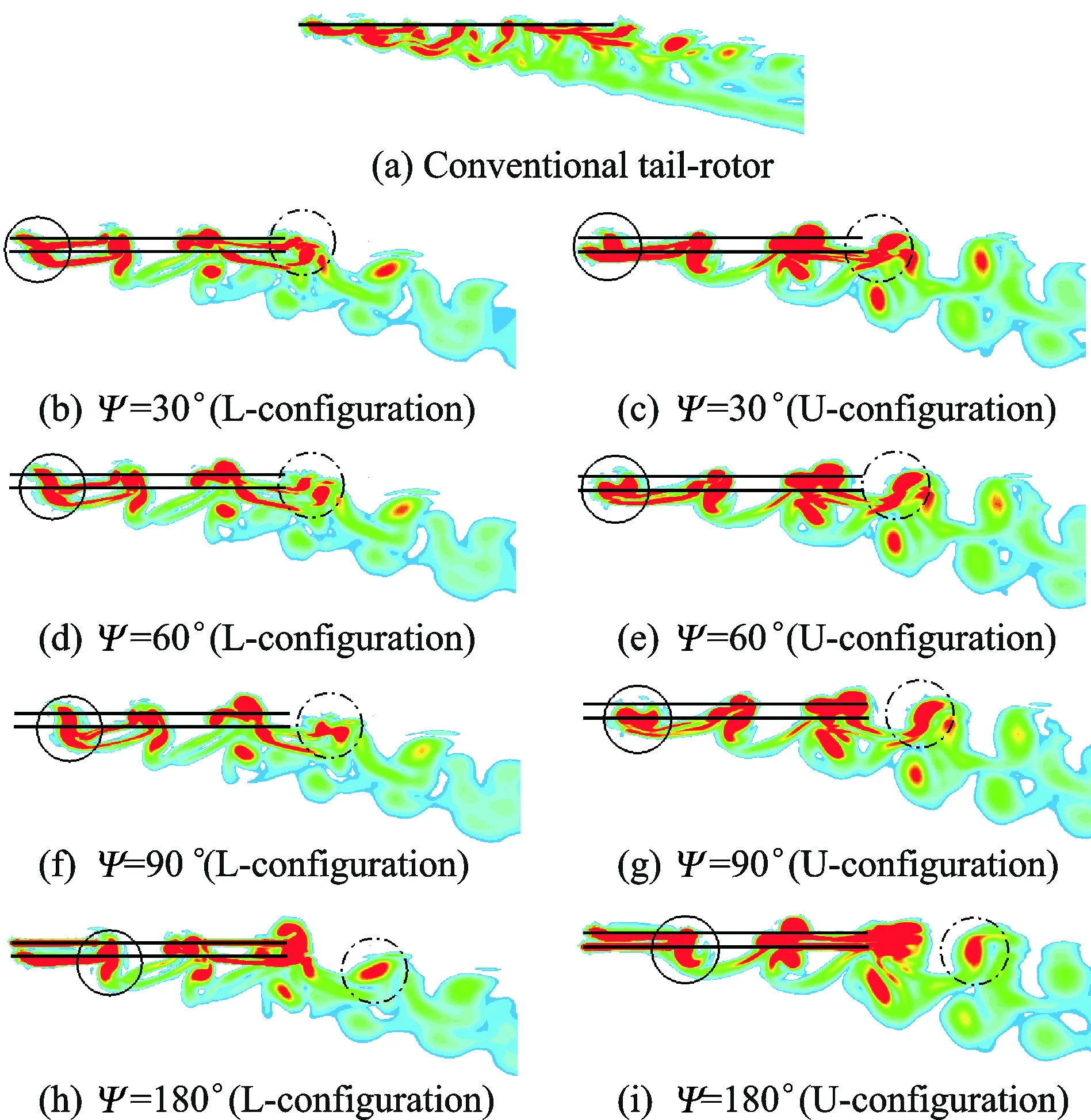
Fig.5 Comparison of tip vortex trajectory for scissor tail-rotor between L- and U-configurations (δ=30°) in forward flight
The BVI phenomenon for tail-rotor often occurs in a forward flight[12]. The smaller blade space of scissor tail-rotors may result in a more severe BVI, which significantly affects the aerodynamics of tail-rotors. Fig. 5 shows the CFD predicted representative snapshots for the tip vortex trajectories of both the L- and U-configurations at different reference rotor azimuth in a forward flight. It can be seen that the tip-vortex shed from the conventional tail-rotor distributes more uniformly than that from the scissor tail-rotor configuration, which is due to the nonuniform azimuthal space between the neighboring blades of a scissor tail-rotor. The severe blade-vortex and vortex-vortex interference will have important impacts on the tail-rotor aerodynamics.
Comparing the front side (solid circle) and the aftward side (dashed circle) of wake structures in Fig. 5, it can be seen that, for the scissor tail-rotor with both the L- and U-configurations, the vortices shed from the neighboring blades form a “vortex-pair” during the process of wake evolution due to the smaller blade spacing, which makes the wake structure of a four-bladed tail-rotor similar to that of a two-bladed tail-rotor. In addition, when vortices convect further away from the tail-rotor blades, the two vortex filaments approach to each other. Furthermore, it can be seen from Fig. 5 that, the downwash velocity of the scissor tail-rotor is smaller than that of the conventional one at the same advance ratio.
2.2Aerodynamic characteristics
Fig. 6 presents the azimuthal variation of the tail-rotor thrust at different scissor angles, where the subscript ORG refers to the conventional (original) configuration, and L30 represents the L-configuration with a scissor angle of δ=30°. All the other labels can be defined similarly. When compared with the conventional one, the thrust of the scissor tail-rotor varies significantly with azimuth angle, and the period is 2/Rev due to the symmetric layout of the lower/upper blades in the scissor tail-rotor. A smaller blade azimuthal spacing between the neighboring blades leads to a stronger aerodynamic interference. Meanwhile, the vertical space of the upper/lower blades can drive the tip-vortex shed from the leading blade be closer to the following blade, which may result in a stronger aerodynamic interference. In addition, the calculation results show that the aerodynamic interference reduces with the increase of scissor angle, which reduces the variation amplitude of the tail-rotor thrust. It should be pointed out that the increased variation of the tail-rotor thrust will have an important effect on the performance and handling qualities of the helicopter installed with the scissor tail rotor.

Fig.6 Effects of scissor angle on unsteady tail-rotor thrust
Fig. 7 shows the effect of the scissor angle on the time-averaged tail-rotor thrust. The results are normalized using the mean thrust of the conventional configuration, i.e., the constant straight-line in Fig. 7 which represents the conventional tail-rotor. The thrust of both the L- and U-configurations are consistently higher than that of the conventional one at all the scissor angles considered. In addition, the L-configuration shows superior aerodynamic performance when compared with the U-configuration, which may be explained by the reduced blade-vortex interaction in the L-configuration (Fig.5).
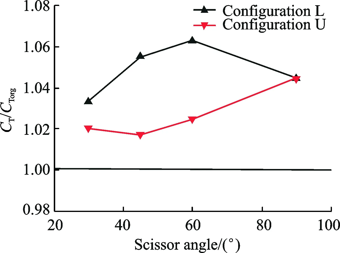
Fig.7 Effects of scissor angle on the time-averaged tail-rotor thrust
Fig.8 shows the azimuthal (unsteady) variation of the thrust on individual blade of both the L- and U-configurations. The general azimuthal variation trend of the scissor tail-rotor is similar to that of the conventional one. However, the blade thrusts of the scissor tail rotor in the azimuthal range of 90°—270° are significantly different from that of the conventional one, which is due to the different patterns of blade-vortex interaction. For example, in the first quadrant (0°—90°) and the fourth rotor quadrant (270°—360°) of the rotor disk, the tip-vortex shed from the preceding blade moves away from the rotor disk, and has a small influence on the following blade. In contrast, in the second and third rotor quadrants (90°—270°), when the tip-vortex moves toward the rear of tail-rotor disk, it encounters the successive blade, which may cause a stronger aerodynamic interference.
In hover, the blade L-2 is far from the tip-vortex shed from the preceding blade, so it suffers little interference. However, as shown in Fig.8, the blade L-2 suffers a very strong aerodynamic interference in a forward flight. It can be concluded that, within the first 90° of the wake age, the tip-vortex convects above the rotor disk, thereby causing the blade L-2 to approach to the tip-vortex shed from the blade L-1. Consequently, the blade L-2 suffers more intense interference in a forward flight compared with that in hovering.
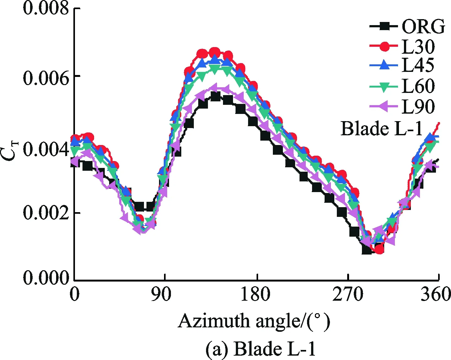

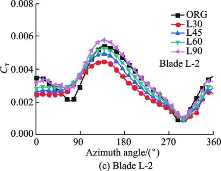

Fig.8 Effects of scissors angle on individual blade unsteady thrust
Fig.9 shows the mean thrust of individual blade versus scissors angle. The mean thrust of each individual blade significantly differs from each other for both the L- and U-configurations. In addition, the difference decreases with an increase in the scissors angle. At all the scissor angles considered, the mean thrusts of the blade L-1 are close to that of the blade U-1. However, the mean thrust of the blade L-2 is consistently higher than that of the blade U-2, which makes the total thrust of the L-configuration higher than that of the U-configuration (Fig. 7).
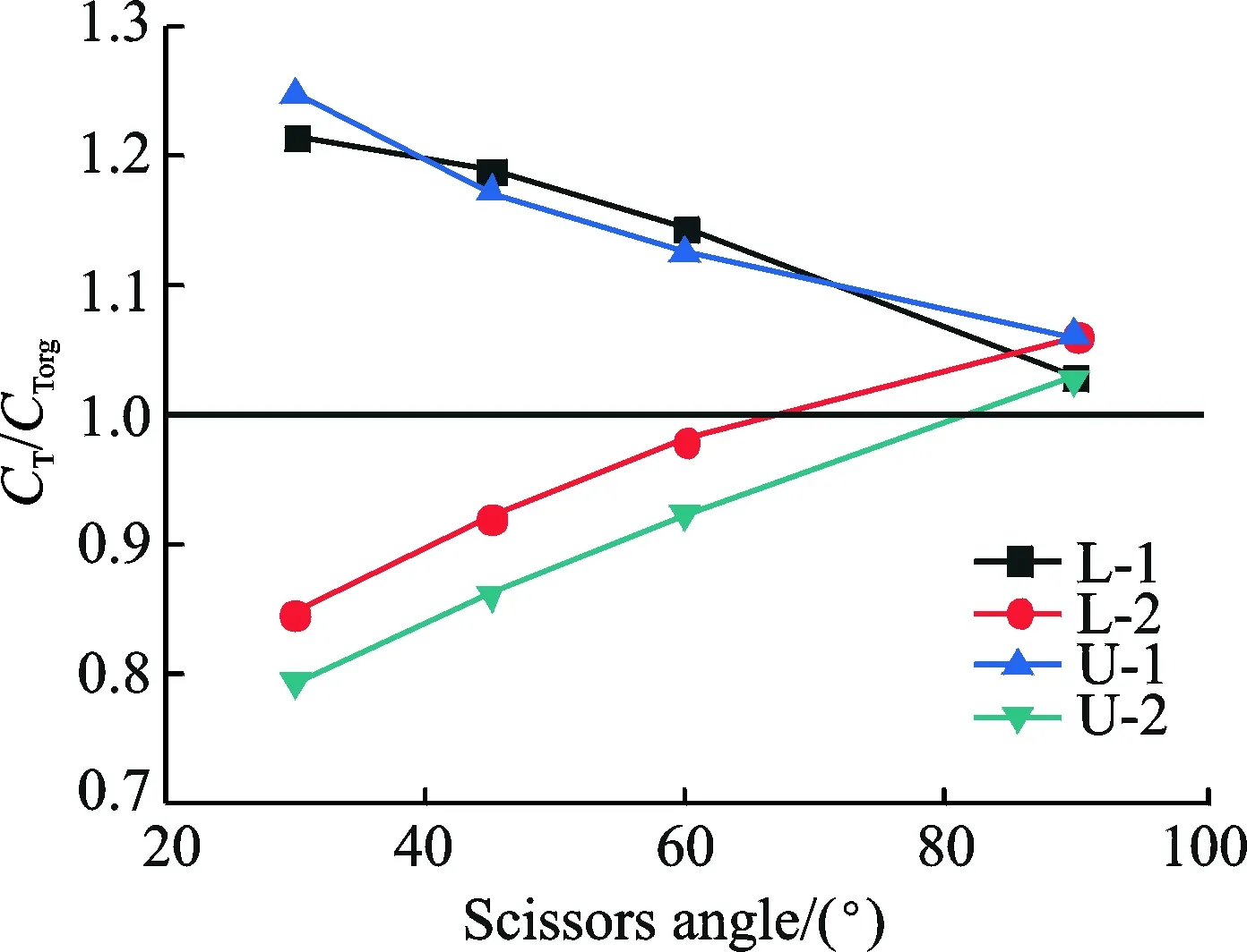
Fig.9 Effects of scissors angle on the mean thrust of individual blade
2.3Acoustic characteristics
To investigate the acoustic characteristics of scissor tail-rotors in a forward flight, the thickness, loading and total noise at several scissors angles are calculated using the developed acoustics solver. The noise is computed on a plane of 100 m×150 m, which is put 30 m away below the tail-rotor disk.
Fig.10 compares the time histories of sound pressure between the scissor and the conventional tail-rotors. Results show that, the phase of the sound-pressure peaks is changed due to the uneven blade azimuthal spacing, which is called the ″modulated effect″[13].

Fig.10 Comparison of time histories of sound pressures between conventional and scissor tail-rotors
2.4Thickness noise
Fig.11 presents the effects of the scissor angle on the thickness noise of the tail-rotor in a forward flight. Since the vertical separation space is insignificant for the thickness noise, the noise between the L- and U-configurations is not explicitly distinguished here. In Fig. 11, the thickness noise level of the uneven spaced layout is lower than that of the conventional one. Also, the thickness noise increases with an increase in the scissor angle. In addition, Fig. 12 shows the maximum thickness sound pressure level (SPL) on the observation plane versus the scissors angle. It can be clearly seen that the maximum thickness SPL increases monotonically with the scissor angle, which means that the so-called ″modulation effect″ is gradually reduced.
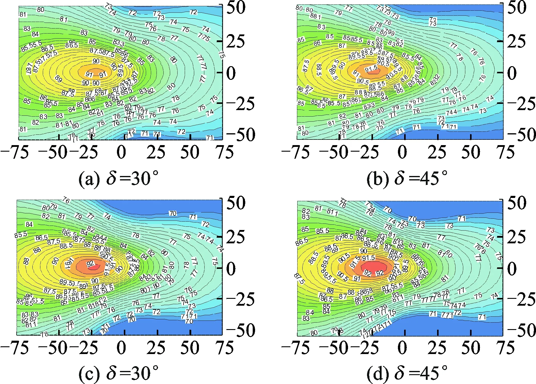
Fig.11 Effects of scissor angle on thickness noise of tail-rotor
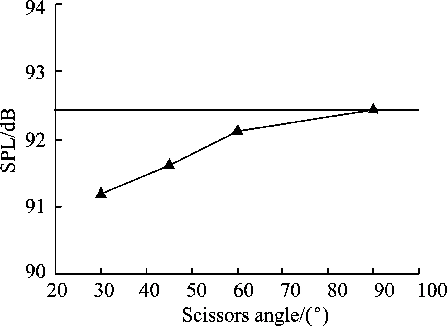
Fig.12 The maximum SPL value of thickness noise v.s.scissor angle
2.5Loading noise
Fig.13 shows the contours of the loading noise SPL calculated on the observation plane, and Fig. 14 presents the variation of the maximum SPL value on the observation plane versus the scissor angle. As shown from Figs. 13,14, as the scissor angle increases, the loading noise level of the tail-rotor decreases initially and then increases. At scissor angles of 45° and 60°, the tail-rotor loading noise levels of both the L- and U-configurations are lower than that of the conventional one. Also, the L-configuration is superior to the U-configuration. The uneven blade azimuthal spacing of scissors tail-rotors changed the phase difference among the sound pressure peaks, which may decrease the amplitude of the some pressure peaks (Fig.10), and therefore decrease the noise level. In addition, the so-called “modulation effect” further modifies the discrete frequency spectrum, which spreads the acoustic energy into more extensive frequency ranges, and therefore decreases the noise level in low- and mid-frequencies. However, as pointed out in the previous section, a reduced blade azimuthal spacing will intensify the aerodynamic interference, and therefore, lead to a larger loading noise in a forward flight.
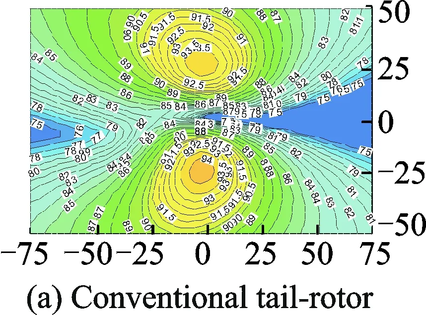

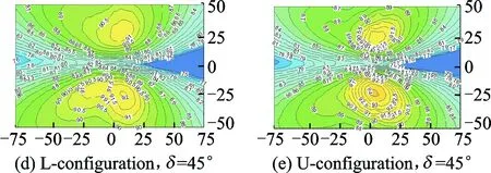
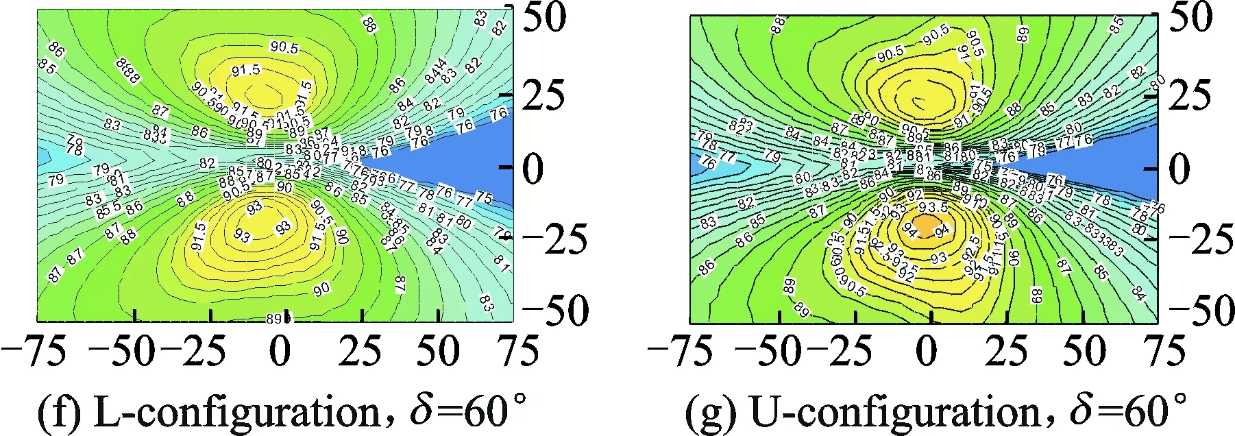
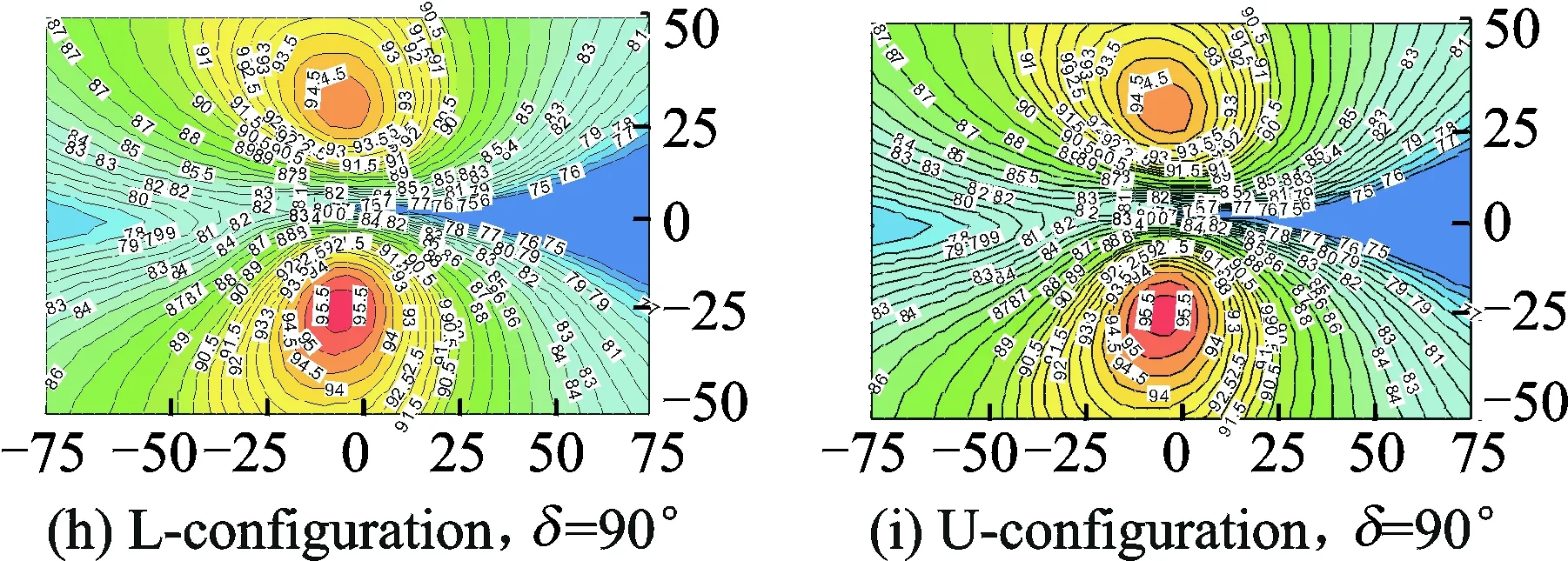
Fig.13 Loading noise characteristics of the scissor tail-rotor
2.6Total noise
Fig. 15 shows the effects of the scissor angle on the maximum SPL of the total noise. The constant straight-line in the plot represents the conventional tail-rotor. As shown, there exists an optimal scissor angle for both the L- and U-configurations in the range of 30°—60° which can make a lowest tail-rotor noise level. For the current tail rotor configuration, δ=45° is the optimal scissors angle.

Fig.15 The maximum SPL value of total noise v.s.scissor angle
3 Conclusions
An unsteady N-S solver and an acoustic solver based on the FW-H equation were combined to calculate the aerodynamic and aeroacoustic characteristics of a scissor tail-rotor. Based on the simulation results and analysis in this paper, the following conclusions can be obtained:
(1) The wake characteristics of a four-bladed scissor tail-rotor with a smaller blade azimuthal spacing are similar to that of a two-bladed tail-rotor.
(2) The scissor tail-rotor suffers more severe aerodynamic interference when compared with the conventional one due to the reduced blade azimuthal spacing.
(3) The aeroacoustic characteristics of the scissor tail-rotor are significantly different from the conventional one. The scissor angle has an important effect on the tail-rotor aeroacoustics. An optimal scissors angle could be determined for achieving the lowest tail-rotor noise level.
(4) The aerodynamic interference reduces with an increase in the scissor angle, which reduces the amplitude variation of the tail-rotor thrust in a forward flight.
(5) The L-configuration is superior to the U-configuration in both aerodynamic and aeroacoustic characteristics.
[1]SONNEBORN W G O, DREES J M. The scissor rotor[C]∥The American Helicopter Society 30th Annual Forum. Washington D. C.: [s.n.], 1974: 18-27.
[2]ROZHDESTENSKY M G. Scissors rotor concept: new results obtained[C]∥ The American Helicopter Society 52nd Annual Forum. Washington D. C.:[s.n.], 1996: 1231-1241.
[3]XU G H, ZHAO Q J, PENG Y H. Study on the induced velocity and noise characteristics of a scissors rotor[J]. Journal of Aircraft, 2007, 44(3): 806-811.
[4]XU G H, WANG S C, ZHAO J G. Experimental and analytical investigation on aerodynamic characteristics of helicopter scissors tail rotor[J]. Chinese Journal of Aeronautics, 2001, 14(4): 193-199.
[5]FAN F, SHI Y J, XU G H. Computational research on aerodynamic and aeroacoustic characteristics of scissors tail-rotor in hover[J]. Acta Aeronautica et Astronautica Sinica, 2013, 34(9): 2100-2109.
[6]ROE P L. Approximate riemann solvers, parameter vectors, and difference schemes[J]. Journal of Computational Physics, 1981, 43(2):357-372.
[7]LUO H, BAUM J D. A fast, matrix-free implicit method for computing low mach number flows on unstructured grids[J].International Journal of Computational Fluid Dynamics, 2000, 14(2):133-157.
[8]SPALART P R, ALLMARAS S R. An one-equation turbulence model for aerodynamic flows[J]La Recherche Aérospatiale, 1992, 439(1):5-21.
[9]BRENTNER K S. Prediction of helicopter rotor discrete frequency noise: NASA Technical Memorandum 87721 [R]. 1986:1-78.
[10]DAVID B S, GLORIA K Y, CHARLES A S, et al. Performance and loads data from an outdoor hover test of a lynx tail rotor: NASA TM-101057[R]. 1989:1-78.
[11]SCHMITZ F H, BOXWELL D A, SPLETTSTOESSER W R, et al. Model-rotor high-speed impulsive noise: full-scale comparisons and parametric variations[J]. Vertica, 1987, 8(4): 395-422.
[12]NEWMAN S. The foundations of helicopter flight [M]. Great Britain: Edward Arnold, 1994.
[13]BRENTNER K S, EDWARDS B D, RILEY R, et al. Predicted noise for a main rotor with modulated blade spacing[J]. Journal of the American Helicopter Society, 2005, 50(1):18-25.
Dr. Fan Feng is an engineer in China Helicopter Research and Development Institute. His research interests lie in helicopter aerodynamics and helicopter aeroacoustics.
Dr. Huang Shuilin is a senior engineer in China Helicopter Research and Development Institute. His research interests lie in helicopter aerodynamics and helicopter preliminary design.
Mr. Lin Yongfeng is a senior researcher in China Helicopter Research and Development Institute. His research interests lie in helicopter aerodynamics and helicopter aeroacoustics.
(Executive Editor: Zhang Tong)
, E-mail address:ff18709598@avic.com.
How to cite this article: Fan Feng, Huang Shuilin, Lin Yongfeng. Numerical calculations of aerodynamic and acoustic characteristics for scissor tail-rotor in forward flight[J]. Trans. Nanjing Univ. Aero. Astro., 2016, 33(3):285-293.
http://dx.doi.org/10.16356/j.1005-1120.2016.03.285
V211.52Document code: AArticle ID: 1005-1120(2016)03-0285-09
 Transactions of Nanjing University of Aeronautics and Astronautics2016年3期
- Transactions of Nanjing University of Aeronautics and Astronautics的其它文章
- Behavior of Corrosion-Repaired Concrete Beams Reinforced by Epoxy Mortar
- Model Updating for High Speed Aircraft in Thermal Environment Using Adaptive Weighted-Sum Methods
- Removing Random-Valued Impulse Noises by a Two-Staged Nonlinear Filtering Method
- Robust Fault-Tolerant Control for Longitudinal Dynamics of Aircraft with Input Saturation
- DNS Study on Volume Vorticity Increase inBoundary Layer Transition
- Stiffness Distribution and Aeroelastic Performance Optimization of High-Aspect-Ratio Wings