Adaptive Correction Algorithm for SAR Trajectory Errors
2014-03-14 01:12:13legSytnik
雷達科學與技術 2014年1期
Оleg V.Sytnik
(A.Ya.Usikov Institute for Radio Physics and Electronics under the National Academy of Sciences of Ukraine,Kharkov,61085,Ukraine)
0 Introduction
Onboard synthetic-aperture radar(SAR)provides the tracking images of the earth surface by coherent processing of the sounding signals reflected from the surface[1-2].The amplitude and phase of the reflected signals contain information about the surface characteristics and objects placed on it.The reflected signals along the tracking trajectory are written in the memory for each strobe of the slant range and then are processed by convolution with a supporting function to produce images.Such a principle of earthtracking is very effective in aircraft-and satelliteboards radars to solve many important scientific and practical tasks.An image can be onboard produced and has a very high spatial(azimuthal and slant range)resolution.
The supporting function of the signal processor is apriori built from the assumption that aircraft trajectory is a straight line.Aircraft deviations from the straight line,which are not taken into account in the signal processing algorithm,cause the image distortions such as defocusing in azimuth and slant coordinates,objects displacement from their real positions,a decrease in the image brightness,an increase in the side lobes of the synthesized antenna and,as a result,the appearance of the repeated targets and some other distortions.Therefore,in most cases,if the aircraft deviation occurs,then in order to obtain a good-quality image,the antenna synthesizing time interval has to be reduced.It leads to resolution degradation.
There are many different methods to compensate those negative effects[3-8].All numerous methods can be divided in the three classes:
a)The first class of the methods in which some information on the SAR trajectory platform position obtains from special onboard sensors of navigation systems,etc.;
b)The second one using the information on the SAR trajectory platform position,which is extracted from the sounding signals reflected from the earth surface;
c)The third class is a combined methods.
The design of the SAR that is invariant to different navigation systems is attractive in term of the second group of methods.It is exactly these particular methods the present paper is devoted to.
1 Problem Statement
In the common case,the algorithm of antenna pattern synthesis in the SAR can be written as a convolution integral for each strobe of slant range[1]:

where mod{·}is the modulus of function;T cis the interval of time during which you are to synthesize an antenna aperture;?x(t-τ)=?s(t-τ)+?n(t)is additive sum the signals,from surface and no coherent noise;the signal is:?s(t-τ)=A(t-τ)e-j(4πri(t)/λ);Ais the amplitude of reflected signal;r i(t)is the current value of the slant range from the phase center of the transmitting antenna to thei-th point reflector placed on a surface;λis the wavelength(the factorω0thas been omitted here);noise is:?n(t),the variance of noise isσ2and its expectation is zero;?h(t)=H(t)ej(2πv2t2/λr0)is the supporting function,whereH(t)is the weighting function which in the simplest case can beH(t)≡1;vis the ground speed of motion of the SAR carrier.
Fig.1(curve 1)shows the antenna pattern synthesized under the ideal condition when there are no trajectory distortions,which is a result of algorithm(1)processing.
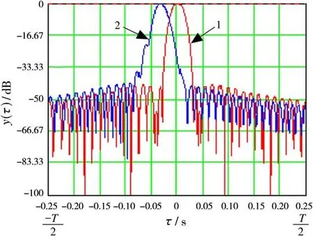
Fig.1 The antenna pattern synthesized under the ideal condition(curve 1),the antenna pattern synthesized with ground speed and acceleration errors(curve 2)
The curve 2 in Fig.1 illustrates the type of distortions which appear in synthesized antenna pattern under the condition of non-stationary of motion of the SAR platform.It is easy to see that errors in ground speed definition lead to displacement of the maximum of the synthesized antenna pattern or targeting errors.To form both patterns we used the Hamming weighting function[9].
The errors in acceleration and jump(the velocity variation of acceleration)of SAR platform leads to an increase in the main lobe width of the synthesized antenna pattern and to an increase in its side lobes.As a consequence,we have geometrical distortions of the objects on an image,their defocusing,a reduced azimuthal resolution and the emergence of repeated targets on the image.
2 Informational Signal
The characteristic of variation in a trajectory signal on the interval of synthesisT cduring radiation of a point target on the earth surface is under the chirp law with frequencyω=4πv(t)t/(λr0).When ground velocity isv(t)=const,the chirp law is a linear function and an envelope of its Doppler spectrum is symmetrical,as see in Fig.2(curve 1).The errors in definition of platform motion lead to distortions of the Doppler spectrum symmetrical structure(Fig.2,curve 2).So it appears attractive to use the analysis of the Doppler spectrum form to correct supporting function in algorithm(1)for automatical correction of trajectory distortions.
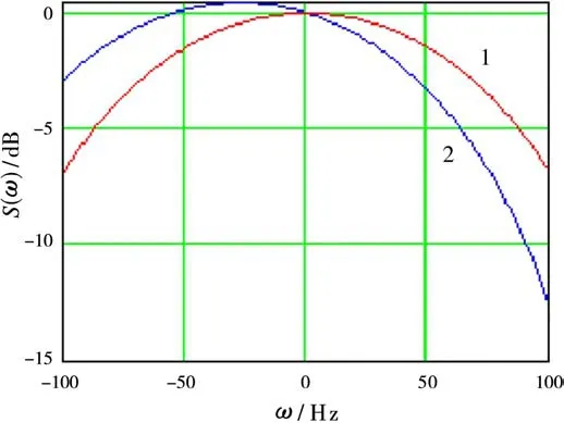
Fig.2 The idealized envelope of the Doppler spectrum form(curve 1)and shifted envelope of Doppler’s spectra form under trajectory distortions(curve 2)
The real reflected signal is highly noisy.As an example,Fig.3 shows(symbols “+”)the trajectory signal spectrum averaged over 128 neighborhood range strobes on the part of trajectory where an aircraft executed maneuvering.Because of high dispersion of the Doppler spectrum envelope samples,it is difficult to construct the procedure for calculating the reliable estimates of their shifts and asymmetry coefficients for correcting supporting function in algorithm(1).However,if spectral samples would be approximated by a well-known function,for example,the polynomial function,then the calculation procedure of correcting coefficients can be implemented.
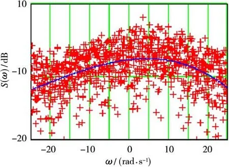
Fig.3 The spectral density of Doppler trajectory signal frequencies during the air craft maneuvering(shown by symbols“+”)and its third-degree polynomial approximation(solid line)
The third-degree polynomial approximation of the Doppler spectrum amplitude envelope with a set of coefficients:24.469;0.024;1.656×10⁻⁵;-4.507×10⁻⁸is shown in Fig.3 by solid line.The polynomial coefficients have been calculated from the next system of equations:
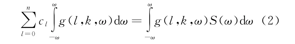
wherek=0,1,…,n+1;nis the polynom’s degree;c lis the coefficient of polynom according to its index;g(l,k,ω)=ωl+k-1is the basic function.Under the criterium of meansquare error,the value of normalized error is

the symbol of expectation operator.In our experiments the value ofσphas been less than 0.248.
Moreover,if one assumes that the SAR platform is not capable to execute the rapid changes in its position relative to the synthesizing interval,and the high-frequency fluctuations caused by platform vibrations are negligible,then in the Maclaurin’s expansion in to series in terms of the power exponent we can use no more than three terms of the series[6].
Then the instantaneous value of slant ranger(t)from the phase center of the real SAR antenna relative to the point reflector on a surface is written as:

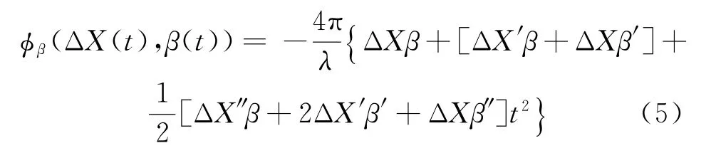
Using formula(3),it is not difficult calculate the projection of phase errors in the supporting function for the aircraft drift along coordinatesX,Y,Z,where coordinateXcoincides with the flight direction,coordinateYcoincides with the line which is perpendicular to the flight line and coordinateZis a normal to the ground surface.

whereΔX,ΔY,ΔZare the errors of aircraft position accordingly toX,Y,Zcoordinates;ΔX′,ΔY′,ΔZ′,ΔX″,ΔY″,ΔZ″are the corresponding derivatives of these errors;vis aircraft’s initial velocity at the momentt;θis the angle between the normal to the ground surface and direction on to the target.
The phase error caused by the combined ambiguity of a sideslip angle and the SAR platform position are defined as a series:
whereβ,β′,β″are the sideslip angle,the velocity of the sideslip angle and the acceleration of the sideslip angle respectively.
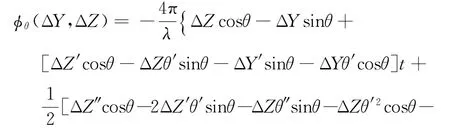
The phase error caused by the combined ambiguity of angleθand the SAR platform position reads as

Now consider in more detail the case where the SAR platform flight velocity is changing on the synthesizing interval.As shown in[4],the phase incursion of a signal from the point reflector to the antenna phase center can be written as:
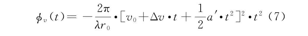
wherev0,Δv,a′is the SAR platform velocity,its acceleration and acceleration derivative respectively.
In order to correct the signal trajectory distortions in the phase factor of the supporting function it is necessary to take into account the coefficientsΔv,a′,which are selected by comparing curve 2(Fig.3)with reference curve 1(Fig.2).To formalize this procedure one can made use of the conjugate gradient method[11].Let us designate the shifted spectral density asS2(ω).The argumentω=ω?,which corresponds to extremumω?is then calculated through iteration of the procedure

where the optimal values of coefficientsαk,βkat each step of the iteration procedure is calculated according to the relation
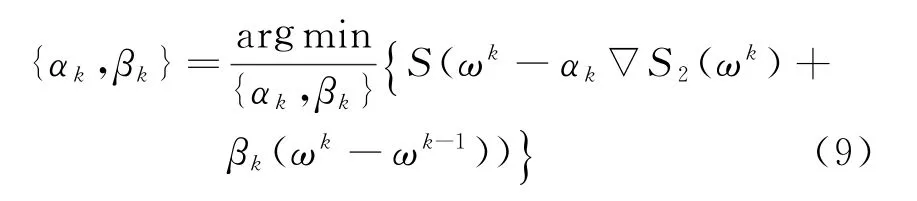
To simplify this procedure the coefficientsαk,βkare chosen in within 0<α≤1,0≤β<1.Then the conjugate gradient method(8)reduces to the heavy ball method[11].
The coefficients Δv,a′are calculated by using procedure(8).For the case shown in Fig.1,the procedure(8)yields the synthetic antenna pattern shown in Fig.4.It takes 36 iterations only atα=0.9,β=0.2.The result is.
As see from Fig.4,the main lobes of both corrected and ideal patterns are equal,but side lobes are not.One can find the residual approximation error at the level minus 50 dB.This error results from the calculation errors of correcting coefficients.This is quite sufficient for most of practical applications.
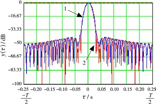
Fig.4 The corrected synthetic antenna pattern(curve 1),ideal synthetic antenna pattern(curve 2)
An effect of using the adaptive correction of an image acquired in synthesizing a hologram of the decimetric-band SAR(λ=0.23 m)is visible when comparing the images shown in Figs 5 and 6.
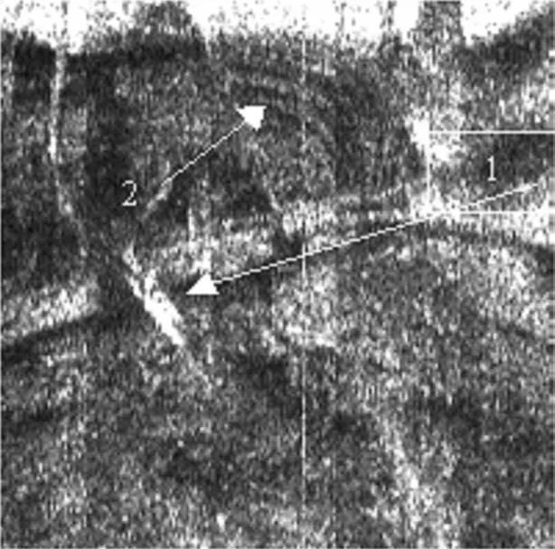
Fig.5 The fragment of the uncorrected synthesized image during aircraft maneuvering

Fig.6 The fragment of the corrected synthesized image during aircraft maneuvering
Specifically,as a result of adaptive correction of the supporting function in(1)the repeated object 1 in Fig.5 has been removed(see Fig.6).The periodical structure on both images(marked by digit 2 in Figs 5 and 6)was unchanged.It is evident that this object is real.To calculate the correction coefficients we used the estimates of Doppler spectrum has shown in Fig.3.
In Figs 7 and 8 has shown the results of signal processing by the proposed method for metric-band SAR(λ=1.8 m).In Figs 5-8 the azimuthal direction is shown from top to bottom,and the direction along the slant range—from left-hand to right-hand.The slant range resolution for the decimetric-band SAR is 22.5 m,and in the azimuthal direction—10 m.The resolution sell for images was 15×37.5 m in Figs 7 and 8.
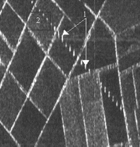
Fig.7 The fragment of the uncorrected synthesized image during aircraft maneuvering

Fig.8 The fragment of the corrected synthesized image during aircraft maneuvering
In Fig.7 one can see the defocused-in-azimuth plane dots which are the columns(marked by digit 1)of electricity transmission lines.In Fig.8 shown that after correcting the synthesized image the same strip has objects like normal targets(marked by digit 2).Besides,the bright solid lines that correspond to the forest belts are well-defined in Fig.8 and appear to the more detailed as compare to Fig.7.
Apart from the visual estimate of quality correction of the synthesized images the quantitative criterium can be used for image analysis.As a criterium we suggested using the comparative analysis of radar’s contrasts along the data row during the flight.For instance,Fig.9 presents the results obtained from synthesizing one row of azimuth uncorrected data and in Fig.10 the result of synthesis of the same data using the proposed a correction algorithm.
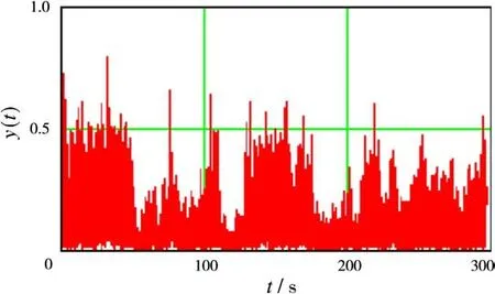
Fig.9 The result from synthesizing one row of uncorrected azimuth data

Fig.10 The result from synthesizing one row of corrected azimuth data
For convenience of comparison,the scale of amplitudes of response from target along the ordinate axis in Fig.9 and 10 is linear,whereas the amplitudes of responses are normalized to maximum in Fig.10.
The total time of data recording was 300 seconds at flight velocity of 487 km/h.The slant range to a strobe was 13 680 m,and the synthesizing interval was 1.8 seconds.
The adaptive correction algorithm was used during the whole flight and,as a result,one can see the growth of image contrasts,in the average,approximately at 10%~20%,and for a separate target(for example,the target within on interval 70 and 90 seconds,see Fig.10)the response amplitude has increased by a factor of almost 1.5.
The generalized block diagram of the adaptive correction algorithm is shown in Fig.11.The procedure for processing the distorted parts of ground surface image is as follows.The initial coherent trajectory signal data is pre-processed by Fourier transform and the trajectory signal samples are concurrently stored on a shift registers.
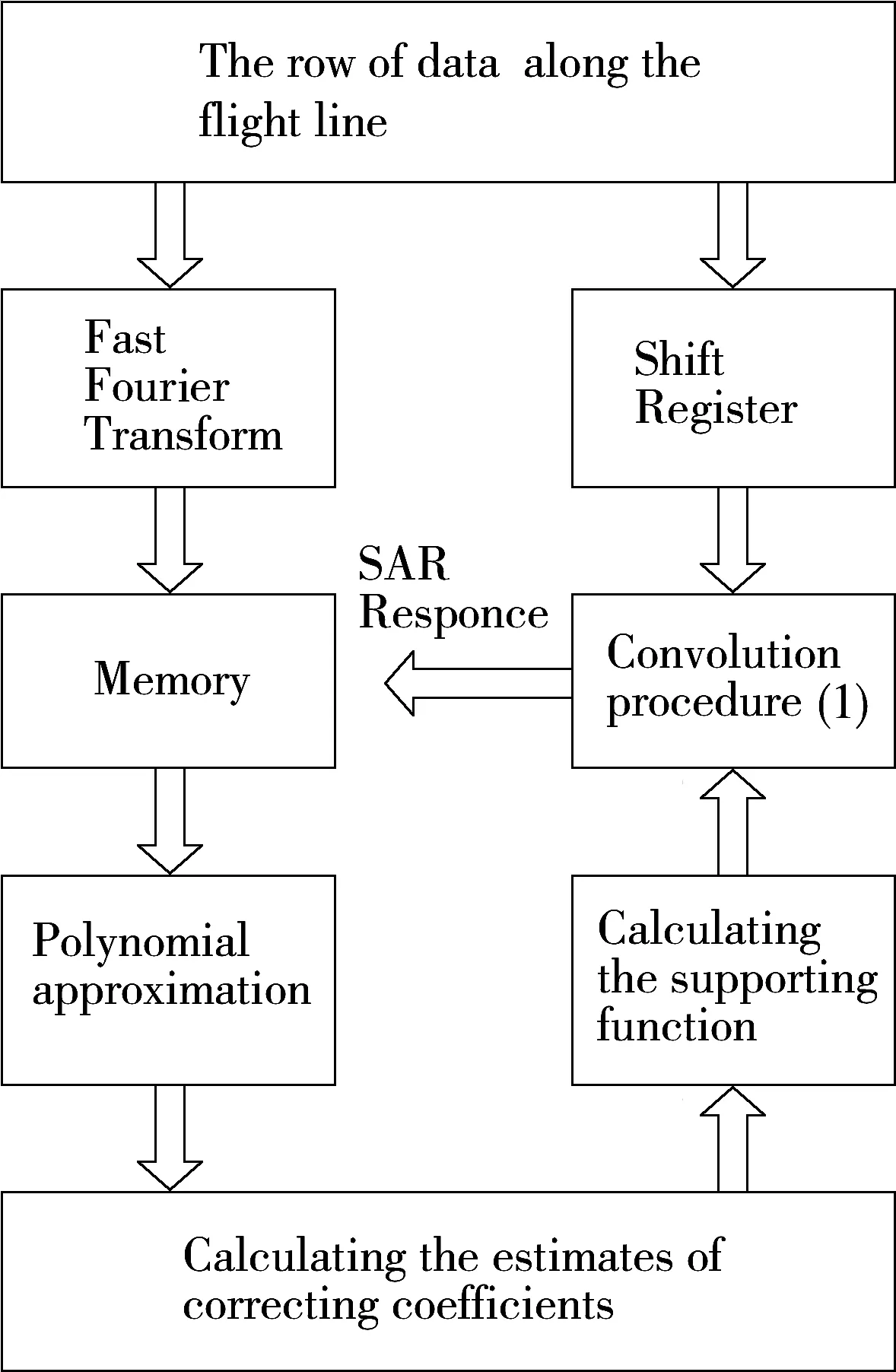
Fig.11 The generalized block diagram of the adaptive correction algorithm
Averaging over several adjacent slant range strobes is used to reduce the dispersion of spectrum samples.The spectral estimate thus obtained is polynomially approximated.The resulting polynom is investigated on an extremum by means of the recursive two-step procedure.This procedure has been chosen in an effort to find a compromise between the convergence rate and the computations per step of one iteration.
3 Conclusion
Thus,we have succeeded in building the adaptive correction algorithm for trajectory errors caused by maneuvering the SAR platform.As a consequence,we had to augment the computations(approximately by 30%per each synthesizing interval).
Theory and practice of using this adaptive algorithm has shown that azimuth resolution on separate areas of SAR images can be increased twice and the amplitudes of responses from some targets have grown by a factor of 1.5.The convergence rate of the recurrent procedure is proportional to geometric progression,and in each case it depends upon the initial shifts from an extremum and the value of fluctuation component Doppler spectrum dispersion.The algorithm allowed calculates the appropriate estimates of flight velocity errors and aircraft acceleration for 30~40 iterations for a real row of data presented in this paper.To accelerate the calculation rate of is made possible by optimizing the parametersαk,βkin procedure(8).
[1]Goryainov V.Radars with Digital Synthesis of Antenna Aperture[M].Moscow:[s.n.],1988.
[2]Tomiyasu K.Tutorial Review of Synthetic Aperture Radar(SAR)with Applications to Imaging of the Ocean Surface[J].Proceedings of the IEEE,1978,66(5):563-583.
[3]Itshoky Y,Sazonov N,Tolstov Y.Main Characteristics of SAR under Arbitrary Platform Motion[J].Radiotehnika and Electronica,1984,29(11):2164-2172.
[4]Hounam D.Motion Errors and Compensation Possibilities[C]∥AGARD Lecture Series 182.Fundamentals and Special Problems of Synthetic Aperture Radar(SAR),[s.l.]:[s.n.],1992:31-42.
[5]Moreira J A.A New Method of Aircraft Motion Error Extraction from Radar Raw Data for Real Time Motion Compensation[J].IEEE Trans on Geoscience and Remote Sensing,1990,28(4):620-626.
[6]Sytnik O.The Criteria of Image Quality of Coherent Radars[J].Kosmitchnanauka and Technology,2002,8(2/3):287-288.
[7]Cumming I,Wong F,Hawkins R.RADARSAT-1 Doppler Centroid Estimation Using Phase-Based Estimators[C]∥CEOS SAR Workshop,Toulouse,France:[s.n.],1999,159-165.
[8]Sharif A H A,Cumming I.Centroid Estimation for Azimuth-Offset SARs[C]∥Proceedings of the IEEE National Aerospace and Electronics Conference,Dayton,Ohio:[s.n.],1995:134-139.
[9]Lawrence M S,William M C.Digital Spectral Analysis with Applications[J].The Journal of the Acoustical Society of America,1989,86(5):2043.
[10]Korn G A,Korn T M.Mathematical Handbook for Scientists and Engineers(2nd ed)[M].New York:Courier Dover Publications,2000.
[11]Polyak B.Introduction in Optimization Theory[M].Moscow:[s.n.],1983.
