Free-walking: Pedestrian inertial navigation based on dual footmounted IMU
2024-04-11 03:38:00QuWngMixiFuJinqunWngLiSunRongHungXinLiZhuqingJingYnHungChnghuiJing
Defence Technology 2024年3期
Qu Wng , Mixi Fu , Jinqun Wng ,*, Li Sun , Rong Hung , Xin Li ,Zhuqing Jing , Yn Hung , Chnghui Jing
a School of Automation Science and Electrical Engineering, University of Science and Technology Beijing, Beijing,100083, China
b Shunde Innovation School, University of Science and Technology Beijing, Fo Shan, 528399, China
c Research Institute of China Unicom, Beijing,100190, China
d School of Artificial Intelligence, Beijing University of Posts and Telecommunications, Beijing,100876, China
e Department of Automation Tsinghua University, Beijing,100084, China
f GEOLOC Laboratory, Universitˊe Gustave Eiffel, Paris, 77454, France
Keywords:Indoor positioning Inertial navigation system (INS)Zero-velocity update (ZUPT)Internet of things (IoTs)Location-based service (LBS)
ABSTRACT The inertial navigation system(INS),which is frequently used in emergency rescue operations and other situations, has the benefits of not relying on infrastructure, high positioning frequency, and strong realtime performance.However, the intricate and unpredictable pedestrian motion patterns lead the INS localization error to significantly diverge with time.This paper aims to enhance the accuracy of zerovelocity interval (ZVI) detection and reduce the heading and altitude drift of foot-mounted INS via deep learning and equation constraint of dual feet.Aiming at the observational noise problem of low-cost inertial sensors,we utilize a denoising autoencoder to automatically eliminate the inherent noise.Aiming at the problem that inaccurate detection of the ZVI detection results in obvious displacement error, we propose a sample-level ZVI detection algorithm based on the U-Net neural network, which effectively solves the problem of mislabeling caused by sliding windows.Aiming at the problem that Zero-Velocity Update (ZUPT) cannot suppress heading and altitude error, we propose a bipedal INS method based on the equation constraint and ellipsoid constraint,which uses foot-to-foot distance as a new observation to correct heading and altitude error.We conduct extensive and well-designed experiments to evaluate the performance of the proposed method.The experimental results indicate that the position error of our proposed method did not exceed 0.83% of the total traveled distance.
1.Introduction
With the increasing need for indoor location-based service(LBS)in various scenarios and sectors, high-precision and highly robust LBS solutions have become a research hotspot [1].Location awareness is emerging as an Internet of Things (IoTs)-enabled technology and an essential part of the ambient assisted living framework [2].Global Navigation Satellite Systems (GNSS) have provided millimeter to centimeter level positioning in outdoor environment [3].Due to the obstruction of satellite signals, it is difficult for global navigation satellite systems to obtain accurate positioning results in indoor environments [4].Therefore, indoor positioning systems built on wireless signals such as cellular [5,6],Radio Frequency Identification (RFID) [7], ZigBee, LiDAR [8], Ultra-WideBand (UWB) [9], Bluetooth [10], and Wi-Fi [11] have been studied and implemented extensively.The unreliable variations in Wi-Fi signals, such as the complicated signal multipath problem,limit its application.Vision-based indoor localization methods achieve high-precision localization results,but privacy and security issues limit their application [12].In addition, issues such as high computational overhead limit its application to embedded devices[13].Visible light-based localization methods achieve high localization accuracy in a small range,but sunlight affects the robustness of the localization system [14].In summary, the existing indoor positioning technologies have their strengths.However, they all have problems such as high deployment costs,small coverage,poor robustness,and low positioning accuracy,which cannot fully meet the high-precision LBS requirements in various application.
With the rapid development of microelectromechanical system(MEMS)technology,MEMS-based inertial navigation systems(INS)play a vital role in providing seamless indoor and outdoor LBS for arbitrary unprepared and unfamiliar environments.Compared with other navigation and positioning methods, pedestrian inertial navigation technology based on MEMS sensors does not need to deploy base stations in advance,and only relies on the sensors they carry, such as accelerometers, gyroscopes and magnetometers, to complete pedestrians’ navigation and positioning [15].Inertial navigation has the characteristics of strong autonomy, high positioning frequency, low power consumption and real-time performance.Therefore, it is more suitable for applications such as individual combat, anti-terrorism action, emergency rescue, and fire rescue where the environment is unknown and infrastructure cannot be deployed in advance, as shown in Fig.1.Especially in military applications, inertial navigation can not only improve training efficiency and duty efficiency, but also provide accurate and continuous location services for areas such as jungles, indoor environments, and urban canyons, enabling multi-soldier collaborative operations.However, the work of such personnel is rather special.In addition to normal walking,more situations are running,turning,going up and downstairs,and even jumping and crawling,which brings greater challenges to navigation and positioning algorithm.
Although there has been much research work on strapdown INS,foot-mounted INS still has the following difficulties and challenges:(1)Low-cost MEMS sensors with poor performance and high noise;(2)The complex and changeable pedestrian motion modes make it difficult to accurately detect the zero-velocity interval (ZVI); (3)Heading and altitude error accumulate over time in Zero-Velocity Update (ZUPT)-assisted pedestrian navigation systems.Thus, the positioning error of ZUPT-assisted INS is not well suppressed and diverges with time and movement distance [16].
This paper aims to improve the ZVI detection accuracy and reduce the heading and altitude drift of foot-mounted INS via deep learning and the equation constraint of dual feet.The key contributions of our study are as follows:
(1) We propose a novel dense sequence labelling mechanism to solve the multiclass window problem.This mechanism can accurately label the data for each timestamp, and then the dense prediction of temporal data is achieved by encoding and decoding data with accurate labelling.
(2) Aiming at the problem that traditional ZVI detectors based on sliding windows cannot provide sample-level detection results,we propose a novel sample-level ZVI detection model based on a dense sequence labelling mechanism and a U-Net network, which outputs binary zero-velocity classification results for each sensor measurement.
(3) We propose a bipedal INS method based on the equality constraint and ellipsoid constraint.This method fuses two monopod systems through foot-to-foot ranging, and uses foot-to-foot distance as a new observation of the Kalman filter to correct heading and altitude error.The method can effectively suppress heading and altitude error, and achieve long-term accurate and stable pedestrian positioning.
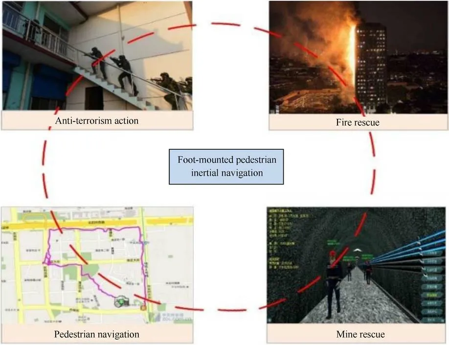
Fig.1.Applications of foot-mounted pedestrian inertial navigation.
(4) We conduct extensive and well-designed experiments to verify the performance of the proposed ZVI detection method and bipedal INS method, and obtain a satisfactory performance.
The remainder of this paper is organized as follows: Section 2 reviews the related literature.Section 3 details the proposed sample-level ZVI and bipedal INS method.Section 4 conducts an extensive experiment to verify the proposed method.Finally, Section 5 draws a conclusion.
2.Related work
The methods for pedestrian inertial navigation can be classified into three categories:(1)Pedestrian dead reckoning(PDR)consists of step detection [17], step length estimation [18] and heading estimation[19],which obtain high-precision positioning results in a short period through device built-in inertial sensors [20]; (2)Deep learning-based inertial odometry [21] recognizes pedestrian’s moving modes and regresses pedestrian’s position without any constraints on the usage mode of the device [21]; (3) The strapdown inertial navigation system(SINS)integrates the angular velocity with time to obtain the attitude change, and double integrates the acceleration with time in the navigation coordinate system to obtain the position change.The SINS sensors can be worn on the waist,calf,head,or upper arm,and more are tied to the foot or built into the insole.In this paper, we focus on foot-mounted inertial navigation.
However, the localization error diverges over time due to inertial sensor noise(i.e.,biases,cross-coupling errors,scale factors and random noise) and non-strapdown relationship between user and device [15].To overcome the divergence of accumulative inertial navigation error, the zero-velocity correction is the most practical constraint method, which consists of two parts: ZVI detection and zero-velocity update.ZUPT technology suppresses error accumulation by the fact that the velocity of pedestrian is zero when the foot contacts the ground [22].ZVI detection is the basis of zerovelocity updating, which directly affects the effect of zerovelocity correction [23].The ZVI detection is often modeled as a hypothesis-testing problem,and statistical detection theory is used to analyze recognize zero-velocity interval [24].Extensive ZVI detection methods based on inertial sensors, including the generalized likelihood ratio test (GLRT) [25], acceleration magnitude(MAG) detector, acceleration moving mean detector, acceleration moving variance (MV) detector, angular rate moving mean detector,angular rate moving variance(ARMV)detector and angular rate energy (ARE)detector, have been proposed.These methods are all based on predefined thresholds,and their performance depends on pedestrian movement patterns and threshold settings.
Selecting the threshold value of each ZVI detection method,which must be selected according to the judgement principle of the zero-velocity state and a large number of experiments, is complicated.In addition, human movement is relatively complex and cannot be in a single movement mode,such as walking all the time.To solve the problem of the fixed threshold method,Ren et al.[26]leveraged a hidden Markov model(HMM)to adaptively adjust the ZVI detection threshold according to pedestrian movement modes.Yang et al.[27]utilized a Mahony filtering algorithm to merge and de-noise the original foot acceleration and angular velocity information to provide high-precision pitch angle information.Then,they utilized the pitch angle sliding variance for zero-velocity detection.Wahlstrom et al.[28] proposed a threshold-adaptive ZVI detection algorithm, which selects the optimal threshold online according to the user's speed, gait frequency, or movement pattern.However, this algorithm requires collecting large quantity datasets at different walking velocities and different movement modes.
With the rapid development of deep learning technology,some researchers try to use a data-driven approach to perform ZVI detection, which can be applied to more general motion models without any manual feature extraction [29].The ZVI detection methods based on deep learning or machine learning import the original inertial measurement units(IMU)data and corresponding labels into the neural network for training, which can effectively solve the dependence of traditional methods on the threshold setting and greatly improve the ZVI detection accuracy [30].Wagstaff et al.[31] used a Long Short-Term Memory (LSTM) neural network to build a ZVI detection model, and improved model performance through rotation,scaling,and dithering.Zhu et al.[32]combined Convolutional Neural Networks (CNN) and LSTM, and used one-dimensional CNN to process raw data to achieve motion classification and improve the ZVI detection accuracy.Chen et al.[23] trained a contrastive neural network by comparing with the known static inertial data to recognize ZVI.Yang et al.[33] proposed Symmetrical-Net that leverages deep Recurrent Convolutional Neural Networks to adaptively detect ZVI.
Researchers have also explored ZVI detection methods based on images, foot pressure, radar signals, and echo feedback, which require additional equipment and are computationally expensive.In addition,the introduction of additional facilities can provide the ZVI detection accuracy, but the positioning system loses its autonomy and cannot deal with emergencies or cannot collect data in advance.
Compared with the ZVI detection accuracy, the heading and altitude error in inertial navigation has a greater impact on the positioning results.In the IEZ framework, the accumulation of the heading error cannot be eliminated.Therefore,limiting the heading error has become a research hotspot.In 2005, Foxlin et al.[34]corrected the navigation error according to the gait characteristics of walking to limit the navigation error, and combined ZVI detection with the extended Kalman filter to form an INS+EKF+ZUPT(IEZ)foot-mounted INS framework.The algorithm not only corrects velocity error, but also helps limit the increase in position and attitude error.Based on the IEZ framework, Zhang et al.[35] proposed the Zero Angular Rate Update (ZARU) method based on the assumption that the heading change is zero when the device is static or quasi-static, which limits the accumulation of gyroscope error and improves the heading stability.Since then, navigation system using the IEZ framework has been widely used.To enhance localization accuracy, scholars have improved various key parts of the IEZ framework.Sun et al.[36] improved the data quality of inertial sensor by calibration to improve the navigation accuracy.
Some studies have attempted to wear multiple inertial sensors on pedestrians, which can use multiple sensors to constrain each other to improve the navigation and positioning results.Zhu et al.[37] and Wu et al.[38] fixed two IMUs on pedestrian feet, using a maximum distance constraint between the feet to improve heading stability.Skog et al.[39] and Chen et al.[40] integrated multiple small and low-cost IMU on a PCB board to form an IMU array,and then used unscented Kalman filtering to fuse the navigation information of multiple IMUs to obtain a more robust and precise heading estimation.Pedestrians will be constrained by the surrounding environment during walking.Therefore, some researchers correct pedestrian inertial navigation error based on map assistance or map matching [41].Khairi et al.[42] used building structures to assist pedestrian navigation, effectively constraining the heading divergence.Sahoo et al.[43] proposed a ramp calibration algorithm that detects ramps on the map and uses the ramp position to correct pedestrian positions to improve localization accuracy.
In addition, some researchers combine foot-mounted INS with Global Navigation Satellite System (GNSS) [3], pseudolite [44],Bluetooth [45], cellular [6], vision [13], LiDAR, ultra-wideband(UWB) [9], Wi-Fi and other wireless positioning technologies to provide absolute position information for foot-mounted INS to enhance positioning accuracy and robustness.However, the method suppresses the heading error by fusing the magnetometer and GNSS can only be used outdoors, and the magnetometer and GNSS will fail in the indoor environment.In addition, the integrating sensors such as cameras and UWB will make the system too complicated and bloated,which is not conducive to the widespread use of pedestrian inertial navigation.
3.Materials and methods
3.1.System architecture
Fig.2 illustrates the overall structure of our proposed pedestrian inertial navigation based on dual foot-mounted IMU.We sanitize inertial sensor noise with a denoising autoencoder.Subsequently,we propose a sample-level ZVI detection method that effectively solves the problem of mislabeling caused by sliding windows.Furthermore, we leverage the equality constraint and ellipsoid constraint to correct heading and altitude error.
3.2.Sensor noise sanitization based on denoising autoencoder
Mining the intrinsic features of inertial sensor measurements can effectively enhance the performance of ZVI detection and INS mechanization.In this study,the denoising autoencoder is utilized to learn the intrinsic characteristics of sensor data before training the ZVI detection model.The autoencoder is an unsupervised learning method with the same size as the input and output layers.Autoencoder consists of encoding and decoding procedures.For input x, the hidden encoding layers predict a target, and the decoding procedure reconstructs the input with z through decoding mirror layers.The objective of autoencoder is to minimize the difference between the raw measurements x of inertial sensors and reconstructed input.
The denoising autoencoder [46] is a stochastic variant of the autoencoder.The denoising autoencoder is an extremely effective tool for learning the essential features,which can be used for noise reduction.Compared with autoencoder, denoising autoencoders require an additional stochastic corruption step in the training phase.As shown in Fig.3, each denoising autoencoder consists of three parts: an encoder layer, a noise-added layer, and a decoder layer.The noise-added layer obtains corrupted inertial data ?x by adding the masking noise to the original sensor measurements x.The encoder layer maps the corrupted data ?x into hidden representation y.
where w is an N×M encoding matrix, and b is a bias vector.M represents the number of input units and N represents the number of hidden units.f(·) denotes the activation function.A similar process is performed by the decoder layer to map the hidden representation back to the raw sensor measurements.
where w′is an M×N decoding matrix, and b′is a bias vector.z is the reconstructed vector.g(·) denotes the activation function.In this paper, we choose the sigmoid function as the activation function.
The goal of denoising is to minimize the reconstruction error,which is done by minimizing the square error loss function L(xi,zi),where
A sparsity term applies to the objective function of the denoising autoencoder to make it work even if there are more hidden units than input units.Therefore,the cost function JDAEis rewritten as
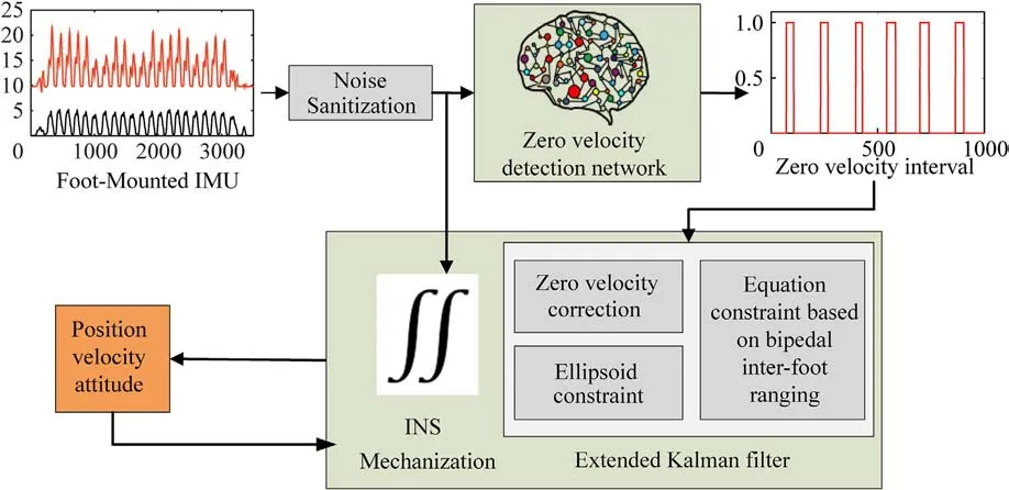
Fig.2.System architecture.
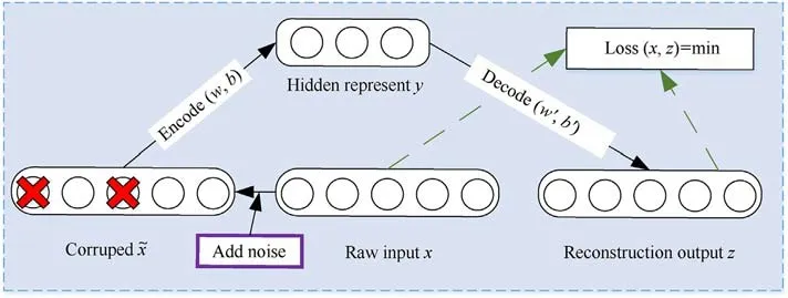
Fig.3.Structure diagram of a denoising autoencoder.
The first term is the cost function of autoencoder, and the second term is the sparse penalty term, where N is the number of hidden units; ρ and ^ρjare the sparsity parameter and the average activation of hidden unit j, respectively; and β is the sparsity penalty.
3.3.Zero-velocity interval detection based on U-Net neural network
ZVI detection is the most critical technology in pedestrian inertial navigation systems based on zero-velocity assistance.Enhancing the ZVI detection accuracy can effectively improve positioning accuracy[16].However,due to the high-frequency foot vibration during pedestrian movement, it is challenging to accurately recognize the zero-velocity state and the non-zero-velocity state from the gyroscope and accelerometer measurements.Especially for mixed motion modes such as running and jumping,further research is needed to accurately detect the ZVI.The traditional ZVI detection methods are based on sliding window, which suffers from a multiclass window problem,i.e.,the samples within each window cannot always share the same label.To solve the multiclass window problem, we analyze the pedestrian gait cycle,present a dense labelling mechanism,and propose a novel samplelevel ZVI detection method based on U-Net neural network.
3.3.1.Gait analysis
A entire gait cycle of pedestrian is defined as the process from the heel of one foot on the ground to the heel of the opposite foot on the ground again when they walk[49].Fig.4 shows the different stages in the pedestrian gait cycle.The time for the foot to fully contact the ground during walking is very short, usually approximately 0.1-0.3 s,and it is even shorter when running[47,48].Fig.5 shows the acceleration change during the walking process.As shown in Fig.5,the periodic amplitude change in the inertial data corresponds to the alternating occurrence of ZVI and non-ZVI,and has a relatively apparent front-to-back dependency in the time dimension.
3.3.2.Traditional zero-velocity interval detection methods
During movement such as walking and running, the feet will alternately leave and touch ground.When their feet touch the ground, the pedestrian's speed is zero.Many research works are based on this phenomenon to correct the positioning error.The traditional ZVI detection methods based on IMU are classified into the following three categories: those based on acceleration, those based on angular velocity, or those based on a combination of acceleration and angular velocity [50].A sliding window is usually used to enhance detection robustness.Detection method based on acceleration amplitude threshold (MAGD) [42],

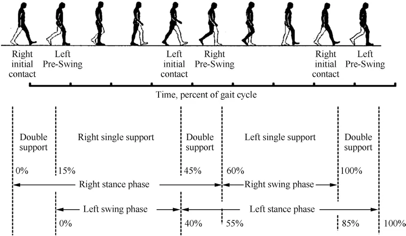
Fig.4.An entire gait cycle [47,48].
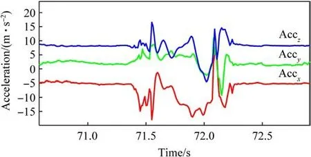
Fig.5.Acceleration variation within one gait cycle.
The above fixed threshold-based methods are excellent for ZVI detection in uniform motion, but when the pedestrian frequently switches motion modes and intensities, the detection accuracy drops sharply[33].
3.3.3.Dense labelling
ZVI detection may be considered as an issue of sequence labelling in which the zero-velocity states at each timestamp in long-term time-series data are anticipated.The traditional ZVI detection method typically uses explicit windowing to segment the data.The explicit windowing method divides data into subwindows of equal length and assigns an identical label to each sample in each subwindow.As illustrated in Fig.6, a multiclass windows occur when samples within a subwindow do not share the same label.In addition, there is no clear consensus on the definite window size to utilize because it is challenging to define the boundaries of state change.
Fig.6 provides a visual comparison of sliding window labeling and dense sequence labeling.Red indicates the swinging phase(S1),and blue represents the stance phase(S2).For instance,when using the labeling strategy with the most occurring classes, the label of this subwindow is assigned as S1.Conversely,S2.However,this subwindow essentially involves class S1 and class S2 information.Therefore, it leads to losing the accurate information of the other class.Using incorrect sequence semantic information leads to an inaccurate recognition result.The bottom of Fig.6 shows that dense sequence labeling can train and predict every sample’s label rather than every window.
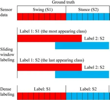
Fig.6.Illustration of sliding window labeling and dense sequence labeling.The top of the figure shows the sensor data in different states, with different colors indicating different state (swing or stance).The middle of the figure shows two different approaches in sliding window labeling, which both lead to loss of label information.The bottom of the figure shows dense sequence labeling, which avoids the multiclass window problem by assigning labels to each sample.
As technical jargon, the term “dense sequence labeling” is proposed by the semantic segmentation field in computer vision.We contributed the dense sequence labeling method to circumvent the multiclass window problem,giving a single label for each sample in every timestamp rather than assigning the same label for each subwindow.The dense sequence labeling result is denoted as YL={y1,y2,…yi,…yL},where yirepresents the state of the ith sample.The output of dense labeling is the same length as the time-series data.
3.3.4.Zero-velocity interval detection
Based on dense labels, we propose a novel sample-level ZVI detection method based on U-Net neural network.U-Net neural network is an improved end-to-end image semantic segmentation network based on a fully convolutional neural network[53],which contains a shrinking path for feature extraction and a dilation path for expanding the size of feature maps.The shrinking and dilation paths are a pair of symmetric structures (encoder-decoder structures).In U-Net, the input image first performs feature extraction on the image through the convolution-pooling operation,then uses deconvolution in the expansion path to enlarge the size of the feature map to the raw image size,and finally predicts category of each pixel to realize semantic segmentation of images.
The model architecture of the proposed sample-level ZVI detection method is shown in Fig.7.We denote the sanitized twodimensional sensor data as a single pixel column and multichannel image with a size of (1, N, C), where N is the length of the input subsequence, and C is the number of the sensor channels.Our method outputs the time of heel strike and toe-off (zero-velocity interval).
3.4.INS mechanization
As shown in Fig.8, INS mechanization obtains the position,velocity,and attitude of an object by integrating acceleration twice and angular rate once provided by accelerometers and gyroscope.Compared with the noise of low-cost MEMS sensors,the navigation performance improvement brought by optimizing parameters such as Earth rotation is negligible.Therefore, the INS mechanization equations can be simplified as follows [54]:
where k is a time index,Δt =tk-tk-1is the time interval between two consecutive observations, pnand vnindicate the position vectors and velocity vectors in the navigation system,respectively,Cnbrepresents the rotation matrix from the carrier system to the navigation system, gn=[0,0,-g]Trepresents the Earth’s gravity vectors in the navigation system, ?fband ?wbrepresent the acceleration and angular rate observation vectors in the carrier system,respectively,baand bgare the bias vectors of the accelerometer and gyroscope, respectively, and Ω[·] is the cross-product form.
3.5.Heading error correction based on equation constraints of bipedal INS and inter-foot ranging
Traditional heading correction methods use magnetometer observations mounted on the IMU to correct heading estimation error.This method can effectively provide position estimation accuracy,but the magnetometer is easily contaminated by building materials,electronic equipment and other external magnetic sources.Other heading correction methods that rely on sources or prior knowledge (WLAN fingerprinting, map matching) require infrastructure to be installed in the area to be located or environmental data to be collected in advance.These methods lose the substantial autonomy of inertial navigation,and cannot be applied to emergencies such as emergency rescue.
To calibrate the heading error while maintaining the autonomy of inertial navigation, we calibrate the heading error by means of bipedal INS and inter-foot ranging.We design a bipedal pedestrian navigation system that consists of two IMU modules and an ultrasonic module.The system obtains the distance between the feet through the ultrasonic module and synchronizes it with the inertial data.The inter-foot distance between is calculated as follows:
where L and R represent the left and right feet, respectively.Ibrepresents the lever arm of IMU module and ultrasound module.pnindicates the position vectors.Cnbrepresents the rotation matrix.ndrepresents the inter-foot distance observation noise with a covariance of σ2d.‖·‖ represents the vector magnitude.In this paper, the bipedal distance is incorporated into the EKF as a new observation.
We define the error state δx as the state estimate ^x minus the true state x.
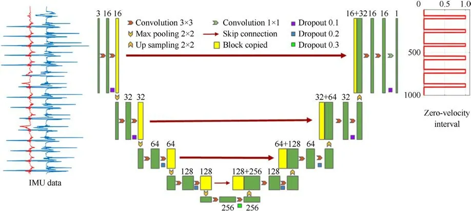
Fig.7.System architecture of the proposed robust zero-velocity interval detection method based on U-Net network.Input refers to IMU raw measurements surrounding the under determining point.Output infers the time of heel strike and toe-off.

Fig.8.INS mechanization.
According to the monopod model,the left and right feet are each subsystem.We combine the two subsystems into a bipedal system by introducing a bipedal intra-foot distance constraint.Correspondingly,the system state vectors δX of the biped are expanded to
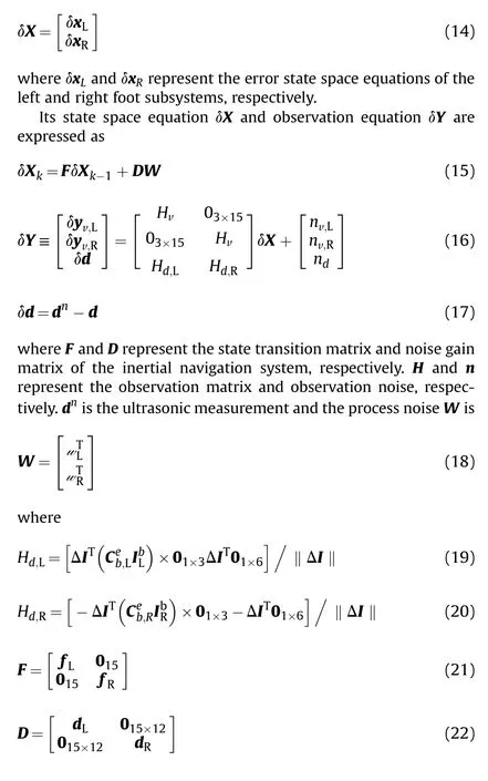
where I represents identity matrix.0 represents zero matrix.C represents the rotation matrix.f represent the acceleration observation vectors.
The filtering process is as follows.
3.5.1.Initialization phase
PLand PRare the covariance matrices of the left and right feet,respectively.
where piirepresents the empirical value of the navigation parameter.
3.5.2.Prediction stage
where δXk-1is the error estimate from the previous step.F and D represent the state transition matrix and noise gain matrix of the inertial navigation system.Since the noises of the two subsystems are independent of each other, the covariance matrix Q of the process noise Wkis calculated as follows:
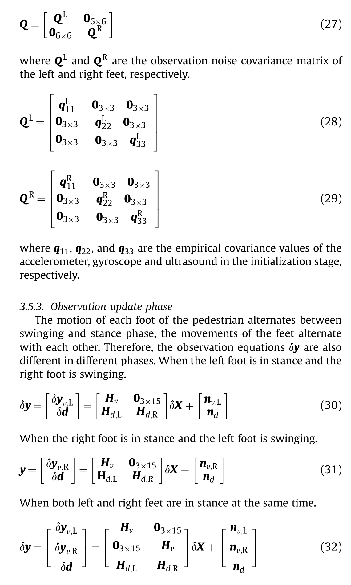
where H and n represent the observation matrix and observation noise, respectively.0 represents zero matrix.
The observation is input into the extended Kalman filter,and the filter gain is calculated.Then,the innovation is calculated, and the innovation is substituted into the state estimation equation to obtain the optimal estimation of the error.Finally, the optimal estimation of the error is compensated for the state obtained by the solution.
3.6.Altitude error correction based on ellipsoid constraint
Although the height error of each step is only centimeters.However, altitude errors accumulate over time and step count,eventually resulting in very significant altitude errors, especially with low-cost sensors.Therefore, altitude error correction is very meaningful and necessary for low-cost inertial sensors.The altitude drift of each step of pedestrians is usually less than 3 cm,which is significantly smaller than the height of stair (decimeters).When the altitude change is less than the threshold,it is considered to be drift and needs to be set to zero; when it is greater than the threshold,it is considered to be a real altitude change and is not set to zero.As shown in Fig.9, the foot lies on a common ellipsoid surface during the neighboring stance phases, the ellipsoid constraint can be used to suppress the drift of altitude.The ellipsoid constraint means that the height change in the same foot(position of foot-mounted IMU)between two adjacent supports is less than a threshold ε.
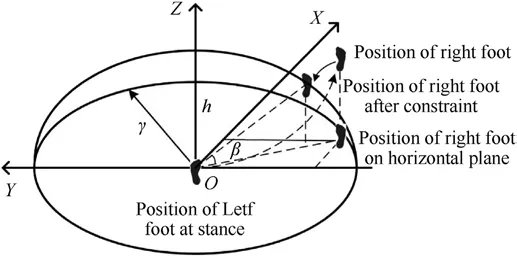
Fig.9.Ellipsoid constraint correction diagram.

where Hecand necrepresent the height observation matrix and observation noise.δX represents the system state vectors of the biped.
In extreme cases,this approach will fail and lead to height errors when the user is walking on a very gentle slope or ramp.This problem can be solved by ramp detection [55].
4.Experimentation and evaluation
We conduct well-designed and extensive experiments on different scenarios to verify the performance of the proposed method.The experimental setup is first introduced.Section B validates the ZVI recognition accuracy.Section C validates the positioning accuracy of the proposed method in typical scenarios.Section D compares the proposed method with other methods in a complex indoor and outdoor environment.
4.1.Experimental setup
To alleviate the heading error,we install an IMU on each foot of pedestrian, and obtain the foot distance measurement value through the ultrasonic ranging module.The two monopod INS subsystems are fused by equality constraints through the inter-foot distance.As illustrated in Fig.10, the proposed system consists of two foot-mounted IMU modules (ICM-42605 [56]), a pair of ultrasound sensors and an Arduino development board for collecting sensor data.The key performance parameters of the IMU module and the ultrasound module are shown in Table 1 and Table 2,respectively.
Inertial navigation is relative positioning.Its positioning error depends not only on the sensor performance and positioning algorithm, but also on the positioning time and travel distance.Therefore, we adopt absolute trajectory error (ATE), distancenormalized relative trajectory error (D-RTE), time-normalized relative trajectory error (T-RTE) and position drift error (PDE) to fully evaluate the performance of the proposed method.To explore the localization error distribution, we introduce the positioning error cumulative distribution function (CDF).
ATE is the major metric used to evaluate the indoor positioning accuracy.ATE is the RMSE of the estimation error and reflects the global consistency between the estimated trajectory and the true trajectory,and the error grows with movement time and distance.
PDE reflects the final position (at timestamp m) drift over the total traveled distance (traj.len).
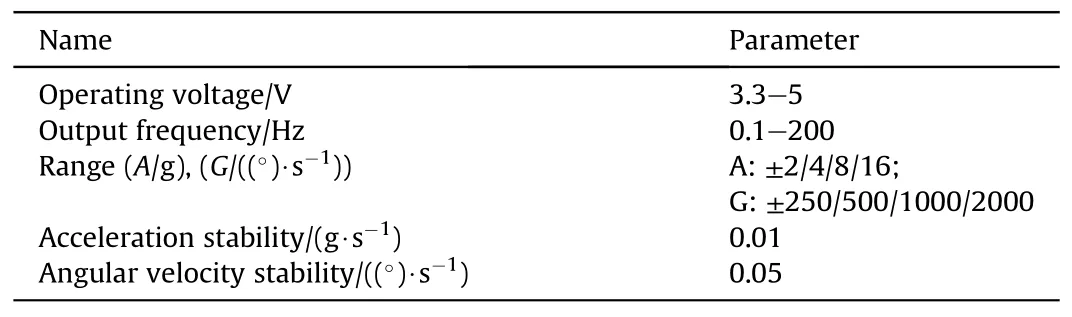
Table 1 Performance parameters of IMUs module.
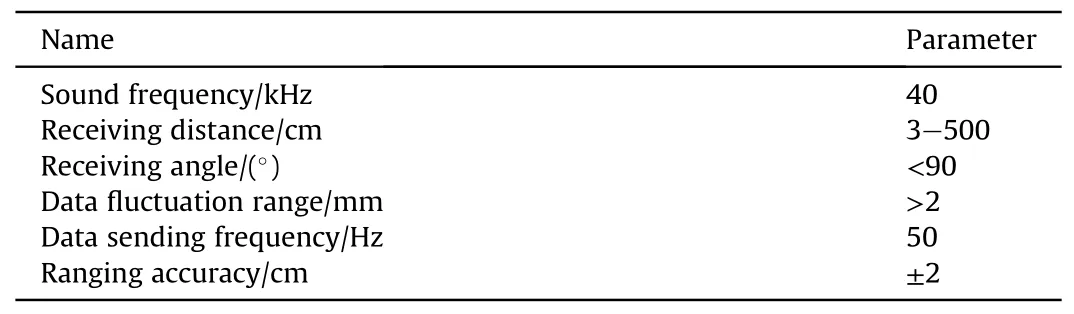
Table 2 Performance parameters of the ultrasonic module.
where xtand ?xtrepresent the position in the ground truth trajectory and in the predicted path at timestamp t,respectively.tdis the time required to travel a distance of d.
4.2.Accuracy of zero-velocity interval recognition
To verify the performance of the ZVI detection method, we compare the proposed method with traditional fixed thresholdbased ZVDs methods (acceleration-moving variance detector(MVD)[51],acceleration-magnitude detector(MAGD)[42],angular rate energy detector (ARED) [52], and stance hypothesis optimal detector(SHOE)[57])and data-driven methods(CNN,LSTM,CNNLSTM).Table 3 compare these methods in typical movement modes(forward walking, backward walking, running, lateral walking).As shown in Table 3, for normal movement (forward walking), the fixed threshold method and the data-driven method are similar,and both achieve more than 95% recognition accuracy.For abnormal movements (backward walking, running, lateral walking),it is difficult for the fixed threshold methods to maintain a recognition accuracy of more than 90%, while the data-driven methods still achieve a recognition accuracy of more than 90%.For abnormal movements, the recognition accuracy of the datadriven method is significantly better than that of the fixed threshold method.As shown in Table 3, the average accuracy of each ZVI detector in different motion modes are 85.80%, 88.05%,89.63%, 90.23%, 93.43%, 95.83%, 97.03% and 98.55%, respectively.The proposed method outperforms other compared methods on four common motion patterns.All compared methods are based on the sliding window for zero-velocity interval detection, only knowing whether there is a zero-velocity point in the window,and cannot specifically detect whether each observation is zerovelocity.The proposed method provides more.The proposed method provides more accurate and finer ZVI detection for each observation.
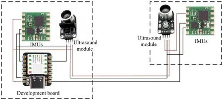
Fig.10.Data acquisition equipment.
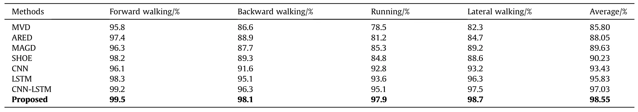
Table 3 Comparison of zero-velocity recognition accuracy in different motion modes.
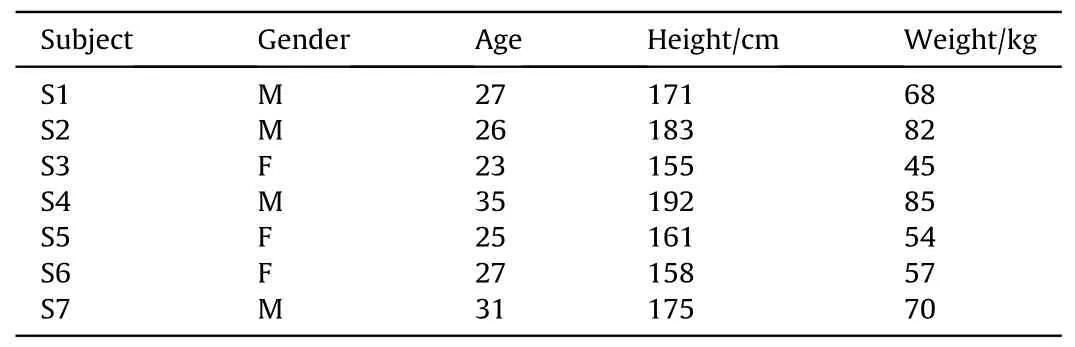
Table 4 Description of volunteers.
In this work, we collect acceleration,angular velocity data, and trained the zero-velocity interval detection model on the PC with python language and PyTorch deep learning platform.U-Net is a neural network with high efficiency and low computational overhead.The zero-velocity interval detection model based on U-Net can efficiently detect the zero-velocity interval in real time.
4.3.Positioning accuracy in typical scenarios
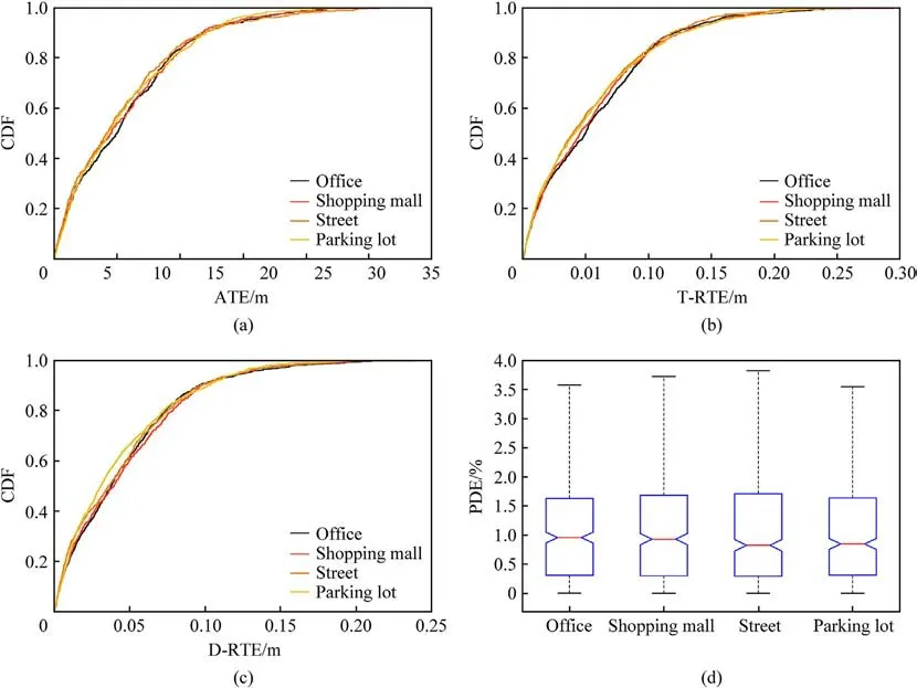
Fig.11.Accuracy comparison in typical scenarios: (a) ATE; (b) T-RTE; (c) D-RTE; (d) PDE.
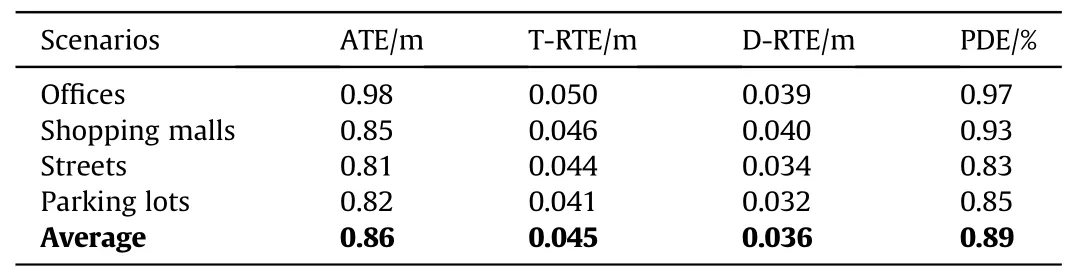
Table 5 Accuracy comparison in typical scenarios.
To more fully and systematically evaluate the proposed positioning method,we invited 7 volunteers to conduct experiments in four typical indoor and outdoor positioning scenarios, including offices, shopping malls, streets, and parking lots.Table 4 details 7 volunteers’ information.Volunteers randomly generated multiple trajectories of 50-300 m in each scenario.The cumulative walking distance of each scenario is approximately 5 km.Fig.11 shows the comparison of localization accuracy for the four scenarios in the form of CDF and boxplot.As shown in Fig.11(a), the 80% ATE of offices,shopping malls,streets and parking lots are 1.90 m,1.87 m,1.83 m and 1.84 m, respectively.As shown in Fig.11(b), the 80% TRTE of offices,shopping malls,streets and parking lots are 0.092 m,0.099 m,0.091 m and 0.096 m,respectively.As shown in Fig.11(c),the 80% D-RTE of offices, shopping malls, streets and parking lots are 0.074 m,0.079 m,0.075 m,and 0.072 m,respectively.As shown in Fig.11(d),the average PDE of offices,shopping malls,streets and parking lots are 0.97%, 0.93%, 0.83% and 0.85%, respectively.The localization performance of the four scenarios is very similar,which proves that the proposed method has satisfactory universality and robustness.Table 5 shows that the average ATE, T-RTE, D-RTE and PDE of the proposed method in typical scenarios are 0.86 m,0.045 m, 0.036 m, and 0.89%, respectively.
4.4.Comparison with other methods
To justify the superiority of our proposed bipedal INS method based on equality constraint and ellipsoid constraint,we compared our proposed method with the following foot-mounted INS.
(1) The IEZ (INS + EKF + ZUPT) framework was proposed by Foxlin et al.[34], which uses ZUPT method to estimate and correct the drift error of the sensors, and then uses an Extended Kalman Filter (EKF) to correct the solution results of the INS.
(2) Wagstaff et al.[31]trained an Support Vector Machine(SVM)to classify pedestrian’s movement modes, adaptively updated the ZVI detector threshold and trained an LSTM-based learning strategy to directly classify pedestrians’ state (stationary or moving).
Fig.12 compares our proposed method and abovementioned methods in a comprehensive environment, including multiple indoor and outdoor scenes.The preplanned comprehensive path is up to 3.3 km, covering typical scenarios, such as cover football fields, indoor passages, round flower beds, streets, outdoor stairs and parking lots.In the comparative experiment, we invited 5 volunteers, and each volunteer walked along the planned path 3 times.
The experimental results are shown in Fig.13.The yellow line of the proposed method is steeper than the other plots, which indicates that the overall error of our proposed method are significantly lower than those of the compared methods.As shown in Fig.13(a),80%ATE of our proposed method is 3.51 m,while those of Wagstaff’s method and IEZ are 5.47 m and 8.89 m,respectively.As shown in Fig.13(b), 80% T-RTE of our proposed method is 0.10 m,while those of Wagstaff’s method and IEZ are 0.15 m and 0.22 m,respectively.As shown in Fig.13(c), 80% D-RTE of our proposed method is 0.06 m, while those of Wagstaff’s method and IEZ are 0.10 m and 0.16 m, respectively.Table 6 demonstrates that our proposed method achieves the best results in terms of ATE,T-RTE,D-RTE and PDE metrics.As shown in Table 6,the proposed method improves the average ATE by 32.18% and 54.38% over Wagstaff’s method and IEZ,respectively.Wagstaff’s method adaptively adjust the zero-velocity detection threshold according to the motion mode to obtain more accurate zero-velocity detection and positioning accuracy.Wagstaff’s method and IEZ are based on the sliding window for zero-velocity interval detection, only knowing whether a certain window is zero-velocity, and cannot specifically detect whether each observation is zero-velocity.The proposed method provides zero-velocity judgment for each observation,while using equality constraints and ellipsoid constraints to effectively suppress positioning errors.

Fig.12.Preplanned comprehensive paths.
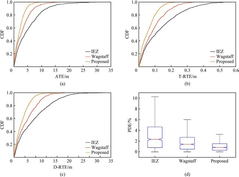
Fig.13.Accuracy comparison of different methods: (a) ATE; (b) T-RTE; (c) D-RTE.(d) PDE.

Table 6 Accuracy comparison of different methods.
5.Conclusions
The main issues of inertial navigation are that the observation contains noise, the pedestrian's complex and changeable movement patterns lead to inaccurate ZVI detection, and the heading and elevation error are difficult to suppress.To conquer these issues, we propose a pedestrian inertial navigation method named free-walking that consists of a sensor denoising module,a samplelevel ZVI detection module, and a dual-foot INS module based on intra-foot ranging.The proposed method not only improves the robustness of ZVI detection in complex motion modes, but also provides sample-level ZVI detection.We proposed a bipedal INS combined with inter-foot ranging.Based on bipedal INS, we establish equation constraints and ellipsoid constraint models,and integrate the bipedal distance as an observation into the bipedal system through EKF.The method can effectively suppress heading and altitude error, and achieve long-term accurate and stable pedestrian positioning.The proposed method does not rely on any additional infrastructure and historical training data to achieve indoor localization.Therefore, the proposed method is not only easy to deploy in arbitrary unfamiliar and unprepared environments,but also easy to integrate with other localization algorithms or IoTs systems.
Declaration of competing interest
The authors declare that they have no known competing financial interests or personal relationships that could have appeared to influence the work reported in this paper.
Acknowledgements
This work was supported in part by National Key Research and Development Program under Grant No.2020YFB1708800, China Postdoctoral Science Foundation under Grant No.2021M700385,Guang Dong Basic and Applied Basic Research Foundation under Grant No.2021A1515110577, Guangdong Key Research and Development Program under Grant No.2020B0101130007, Central Guidance on Local Science and Technology Development Fund of Shanxi Province under Grant No.YDZJSX2022B019, Fundamental Research Funds for Central Universities under Grant No.FRF-MP-20-37, Interdisciplinary Research Project for Young Teachers of USTB (Fundamental Research Funds for the Central Universities)under Grant No.FRF-IDRY-21-005, National Natural Science Foundation of China under Grant No.62002026.

- Defence Technology的其它文章
- Evolution of molecular structure of TATB under shock loading from transient Raman spectroscopic technique
- MTTSNet:Military time-sensitive targets stealth network via real-time mask generation
- Vulnerability assessment of UAV engine to laser based on improved shotline method
- Investigation of hydroxyl-terminated polybutadiene propellant breaking characteristics and mechanism impacted by submerged cavitation water jet
- Estimation of surface geometry on combustion characteristics of AP/HTPB propellant under rapid depressurization
- Numerical study on the blocking effect of skin on Flash-Ball Impact and damage assessment