Mixed Electric and Magnetic Coupling Design Based on Coupling Matrix Extraction
2024-01-12 14:48:40XIONGZhiangZHAOPingFANJiyuanWUZengqiangGONGHongwei
ZTE Communications 2023年4期
XIONG Zhiang, ZHAO Ping, FAN Jiyuan,WU Zengqiang, GONG Hongwei
(1. Xidian University, Xi’an 710000, China;2. ZTE Corporation, Shenzhen 518057, China)
Abstract: This paper proposes a design and fine-tuning method for mixed electric and magnetic coupling filters. It derives the quantitative relationship between the coupling coefficients (electric and magnetic coupling, i.e., EC and MC) and the linear coefficients of frequencydependent coupling for the first time. Different from the parameter extraction technique using the bandpass circuit model, the proposed approach explicitly relatesEC and MC to the coupling matrix model. This paper provides a general theoretic framework for computer-aided design and tuning of a mixed electric and magnetic coupling filter based on coupling matrices. An example of a 7th-order coaxial combline filter design is given in the paper, verifying the practical value of the approach.
Keywords: coupling matrix; frequency-dependent coupling; mixed electric and magnetic coupling; parameter extraction
1 Introduction
In the design of microwave filters, the realization of finite transmission zeros (TZs) is critical to improving selectivity. Cross-coupling is the most popular method to create TZs[1]. However, this multi-path mechanism often leads to complexity in the design of filter layout, especially for highorder filters with many TZs. To solve this problem, frequencydependent coupling (FDC) is introduced into the filter design.In an FDC, the coupling coefficient will be zero at a specific frequency, creating extra TZs in a given filter network.
SZYDLOWSKI et al.[2-5]proposed an optimization-based approach to the synthesis of coupling matrices with FDCs.Years later, HE[6-7]and ZHAO[8]developed deterministic matrix transformation approaches that can eliminate one crosscoupling from traditionalN-tuples and introduce FDCs into the network. Constant couplings can be realized as pure electric or magnetic coupling, whereas FDCs need to be implemented as mixed electric and magnetic couplings. However,the mixed electric and magnetic coupling is difficult to control, because there is no quantitative relationship between FDCs and the mixed electric and magnetic couplings.
In 2006, MA[9]proposed constructing an electrical coupling and a magnetic coupling path between two resonators to generate a TZ. However, he did not give the relationship between the TZ position and the electric and magnetic coupling coefficients. In 2008, CHU[10-11]defined the mixed electric and magnetic coupling coefficient and gave the extraction method of the electric coupling coefficient (EC) and the magnetic coupling coefficient (MC) from the electromagnetic (EM) simulation of mixed electric and magnetic coupling structures. Furthermore, the relationship between the location of TZ and (EC,MC) is found. However, the parameter extraction is carried out in the bandpass domain. The approach does not explicitly relate Ec and Mc to the coupling matrix model, which is popular in filter synthesis. Therefore, it is difficult to design or tune the mixed coupling by coupling matrix extraction approaches.
This paper derives the explicit relationship between EC(MC)in the mixed electric and magnetic coupling and elements in the coupling and capacitance matrices. With the coupling matrix extracted by the model-based vector fitting (MVF) technique[12], the filter designer can easily design and tune the mixed coupling filter by comparing the extracted matrices with target ones.
The rest of the paper is organized as follows. Section 2 derives the relationship between the lowpass FDC model and the bandpass mixed coupling coefficients (ECand MC). Section 3 presents a mixed electric and magnetic coupling physical model. The theory proposed in Section 2 is applied to design the mixed coupling structure. We then demonstrate a 7thorder in-line mixed coupling filter design with the aid of coupling matrix extraction. Section 4 concludes this paper.
2 Relationship Between FDC and Mixed Electric and Magnetic Coupling
A constant coupling in the coupling matrix is modeled by an ideal J-inverter, the π-equivalent circuit of which consists of three frequency-invariant susceptances (FISs). The characteristic admittance of a frequency-dependent inverter varies with frequency. Fig. 1 shows the π-equivalent circuit model of the frequency-dependent inverter. The circuit model includes three capacitors parallel-connected with FISs.
Note that the FDC is an element in lowpass circuit models.The bandpass frequency is mapped to the lowpass frequency domain by:
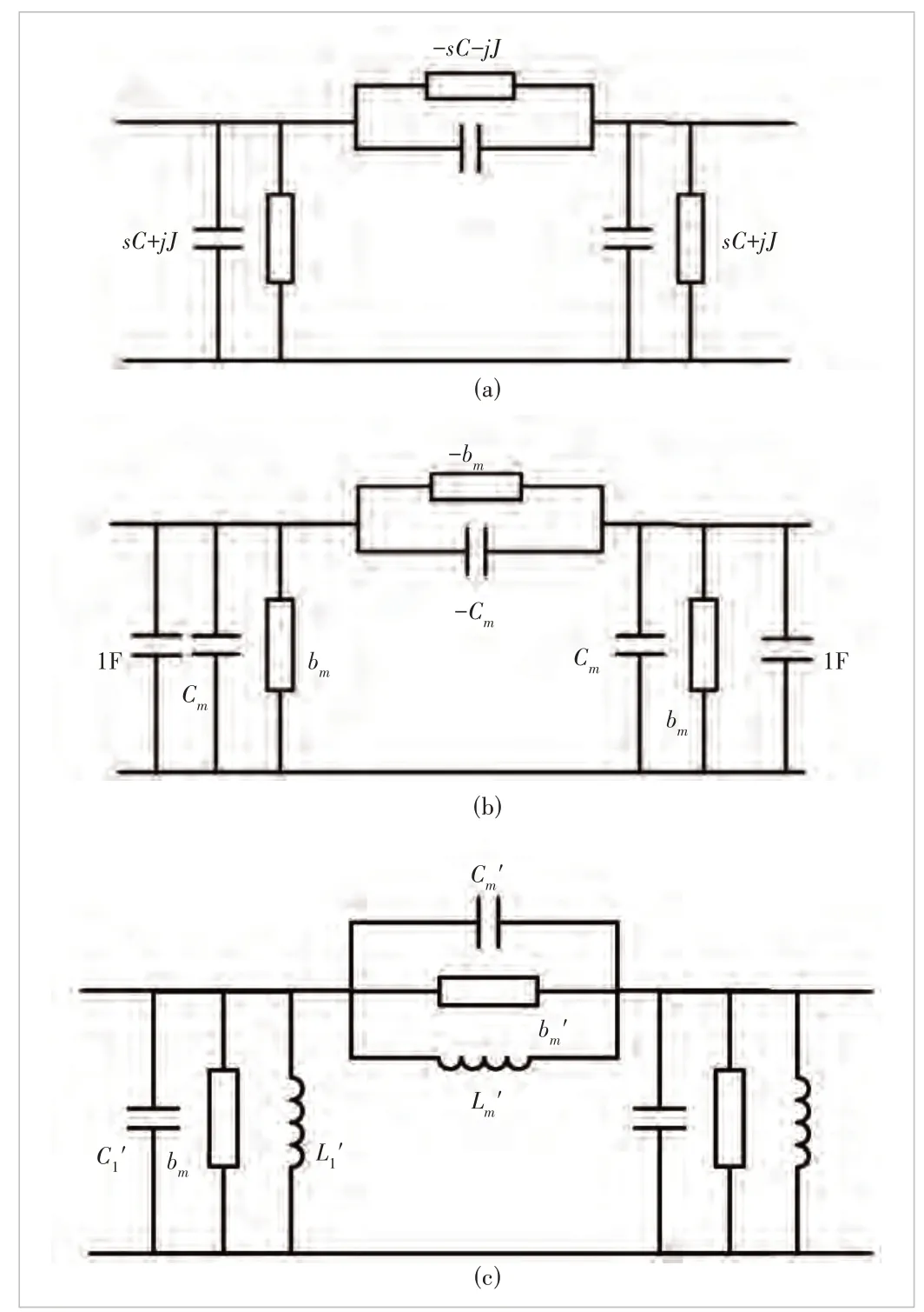
▲Figure 1. π-equivalent circuit model: (a) frequency-dependent inverter, where the admittances of capacitance and frequency-invariant susceptances are sC( - sC) and jJ( - jJ) respectively; (b) frequencydependent inverter coupled lowpass network consisting of two resonators, where the two resonators are unit capacitors and resonant frequency is zero rad/s; (c) bandpass circuit model of mixed electric and magnetic coupling
whereΩis the normalized lowpass frequency,ω0is the center frequency of the bandpass filter,ω2is the upper band edge frequency,ω1is the lower band edge, andωis the bandpass frequency.
Substituting Eq. (1) into the admittance formula of FIS and capacitor connected in parallel yields
whereCLPis the capacitance in the lowpass circuit model,CBPis the capacitance, andLBPis the inductance in the bandpass circuit model. According to Eq. (2), the parameters in the lowpass and bandpass circuits are related by:
where BW is the bandwidth and 2πBW=ω2-ω1. After transformation, the coupling between two resonators is not a pure electric or magnetic coupling form but mixed coupling.Therefore, an FDC should be realized as a mixed electric and magnetic coupling. However, Eq. (3) cannot reveal the qualitative relationship between FDC and mixed electric and magnetic coupling.
As shown in Fig. 1(b), there are unity capacitors on both sides of the frequency-dependent inverter. The capacitors model parallel resonant circuits with a resonant frequency of zero rad/s. The value of the frequency-dependent inverter issCm+jbm. If the left node index isiand the right node index isj,the coupling matrix elementMijisbm,and the capacitance matrix elementCijisCm. After lowpass-to-bandpass circuit transformation in Eq. (3), the resultant bandpass circuit model is shown in Fig. 1(c), where
In the above derivation, we use the narrowband condition ofω0>> BW. This condition also applies to the derivation of Eqs. (7), (9) and (10).ωmis the resonant frequency. When the frequency isωm, the parallelCm',Lm'andbm'form an open circuit, and the signal transmission is blocked to generate a TZ.
For a mixed electric and magnetic coupling, the calculation formula of Ec and Mc can be expressed as follows[10]:
whereωevis the even mode resonant frequency, andωodis the odd mode resonant frequency of a coupled resonator pair.
We can calculate ECand MCin the mixed electric and magnetic coupling based onωm,ωev, andωod. To obtain ECand MCof the mixed electric and magnetic coupling in terms of FDC coefficients, we can analyze the even- and odd-mode resonant frequencies of the coupled-resonator circuit model in Fig. 1(c).
We analyze the odd mode first. The odd-mode sub-circuit is shown in Fig. 2(a). After combining parallel-connected capacitors, inductors, and FISs, the odd-mode sub-circuit is transformed into the form shown in Fig. 2(b). We have:
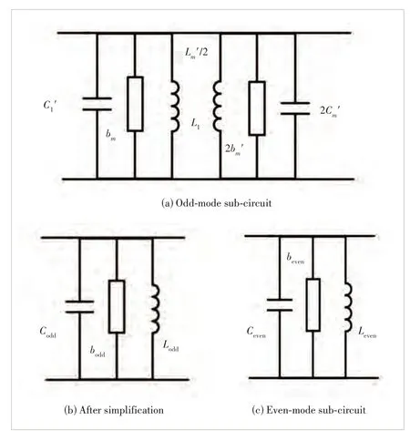
▲Figure 2. Mode circuit of a bandpass circuit model of mixed electric and magnetic coupling
Therefore, the resonant frequency of the odd mode is
Similarly, to analyze the even mode, as shown in Fig. 2(c), we have
Therefore, the resonant frequency of the even mode subcircuit is
Substituting Eqs. (7) and (9) into Eq. (5) yields
The results in Eq. (10) show that ECand MCin mixed electric and magnetic coupling filters are almost equal, and both values are approximately equal to -Cm. This analysis result reveals that the majority of electric and magnetic coupling should be canceled with each other to realize an FDC. The electric coupling or magnetic coupling is slightly stronger than the other one to provide a weak total coupling for constructing the narrowband passband. Therefore, if the absolute value of the synthesized capacitance matrix elementCijis larger, the electric and magnetic coupling in the mixed coupling structure should be tuned stronger simultaneously.
To conclude, the FDC in the lowpass coupling matrix model issCij+jMij, whereMijrepresents the total coupling exhibited by the mixed electric and magnetic coupling at the center frequency, andCmis related to the strength of both the electric and the magnetic coupling coefficient in the mixed coupling.
3 Analysis of Electromagnetic Model
For the experimental validation, a 7th-order in-line bandpass filter is designed with coaxial cavity structures in this section.The 7th-order filter contains two mixed electric and magnetic couplings, the structure of which is shown in Fig. 3(a). The simulation results of the second-order filter block are shown in Fig. 3(b). The center frequency of the filter is 3.5 GHz, the bandwidth is 0.2 GHz, and the return loss is 18 dB. The open end of the metal rod is connected to a folded metal sheet.Two adjacent metal sheets form a parallel plate capacitor to realize a strong electric coupling. The height of the platehplateis 3.6 mm. The short ends of adjacent coaxial resonators are connected by a metal ridge to realize a strong magnetic coupling. The height of the ridge,hridge, is 6.3 mm. The strong electrical coupling and the magnetic coupling exist simultaneously to form a mixed electric and magnetic coupling. Ifhplateorhridgeincreases, the electric coupling or magnetic coupling will become stronger in this design.
By repeatedly applying the MVF technique to extract the coupling matrix from simulation data[12], we can study the relationship between the mixed coupling coefficients and the element values of the coupling and capacitance matrices. Tables 1 and 2 show the extracted values ofMijandCijwhen ECand MCare changed. It can be found from Table 1 that whenhridgeandhplateincrease simultaneously,Cijincreases, whereasMijalmost does not change. Therefore,Cijis related to both the electric and magnetic coupling coefficients in the mixed coupling.
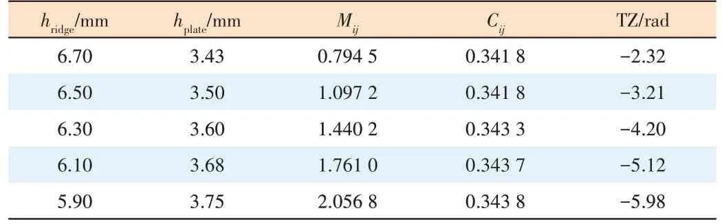
Table 2 shows that when ECincreases and MCdecreases,Mijincreases. SinceMijrepresents the total coupling exhibited by the mixed electric and magnetic coupling at the center frequency, it can be seen that ECis stronger than MCin the mixed coupling structure shown in Fig. 3(a). Table 2 also shows that we can controlMijby increasing the difference between ECand MCwithout affectingCij.
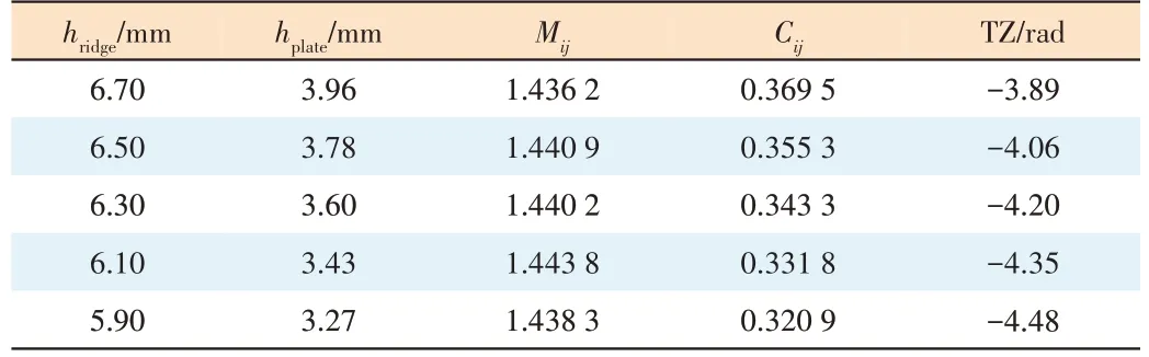
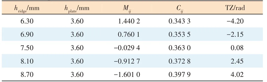
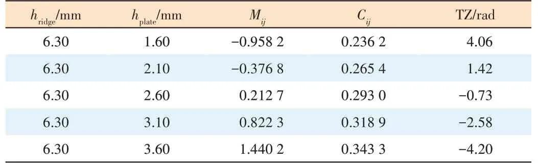
Table 3 shows that when MCincreases, the TZ is shifted tothe right. From Table 4, it can be found that when ECincreases, the TZ is shifted to the left. From Tables 3 and 4, we can also see that when the TZ is located in the lower stopband,ECis stronger than MC. If the TZ is in the upper stopband,then MCis stronger than EC.
▼Table 1. Simultaneously changing the heights of the ridge and the plate
▼Table 2. Changing the height of the ridge or the plate
▼Table 3. Changing the height of the ridge or the plate when TZ is in the lower stopband
To conclude, the tuning of the mixed electric and magnetic coupling structure in Fig. 3(a) follows two rules:
Rule 1: We simultaneously increase or decrease ECand MCto tuneCij.
Rule 2: If the TZ is in the lower stopband, we can increase ECand decrease MCto increaseMij. If the TZ is in the upper stopband, we can increase MCand decrease ECsimultaneously to increaseMij.
To verify the above theory, take a 7th-order filter with the coupling topology shown in Fig. 4(a) as an example. The center frequency and bandwidth of the filter are 3.5 GHz and 200 MHz, respectively. The in-band return loss level is required to be 18 dB. Two TZs at 3.7 GHz and 3.3 GHz are generated sequentially by two mainline FDCs. The synthesized coupling matrix and capacitance matrix are shown in Figs. 5 and 6, respectively.
The perspective view of the filter model is shown in Fig. 4(b).With the help of the MVF method to extract the coupling matrix from simulation data, we can identify how to adjust the dimensions and finally obtain satisfactory filter responses. The simulation results with ideal lossless materials are shown in Fig. 7,where solid lines are simulation data, and dashed lines are theideal synthesis responses.
▼Table 4. Changing the height of the ridge or the plate when TZ is in the upper stopband
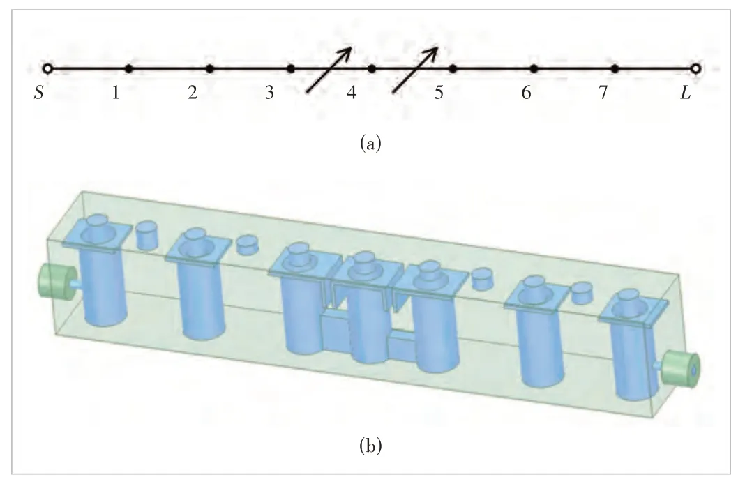
▲Figure 4. 7th-order filter with mixed electric and magnetic coupling:(a) target topology and (b) electromagnetic model of the 7th-order filter with mixed electric and magnetic coupling
4 Conclusions
In this paper, the relationship between the coupling matrix(capacitance matrix) and EC(MC) is obtained through circuit analysis. A filter example is designed to verify the proposed theory. Although only the inline filter is discussed in detail,the strategy introduced in this paper can be easily generalized to mixed electric and magnetic coupling filters in different coupling topologies. Compared with the existing theory of mixed electric and magnetic coupling filters, this work has the following distinctive features.
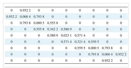
▲Figure 5. Coupling matrix
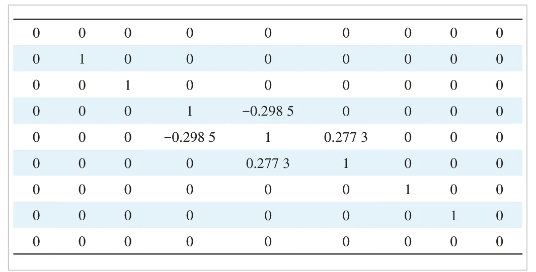
▲Figure 6. Capacitance matrix
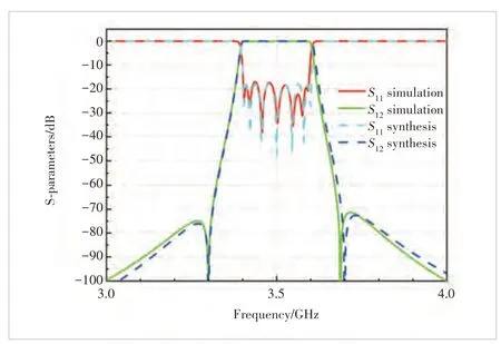
▲Figure 7. Response of the 7th-order, where dashed lines are ideal synthesis responses and solid lines are simulation results
1) It derives the explicit relationship between EC(Mc) in the mixed electric and magnetic coupling and elements in the coupling and capacitance matrices.
2) The filter tuning procedure is based on analytical coupling matrix extraction and thus is very fast, compared with optimization-based filter tuning techniques.
This paper gives a guiding idea for designing the physical model of the mixed electric and magnetic coupling filter.

- ZTE Communications的其它文章
- Table of Contents, Volume 21, 2023
- Special Topic on 3D Point Cloud Processing and Applications
- Beyond Video Quality: Evaluation of Spatial Presence in 360-Degree Videos
- A Hybrid Five-Level Single-Phase Rectifier with Low Common-Mode Voltage
- Incident and Problem Ticket Clustering and Classification Using Deep Learning
- Research on Fall Detection System Based on Commercial Wi-Fi Devices