基于激活函數(shù)的LCC-S型無(wú)線電能傳輸系統(tǒng)建模和穩(wěn)定性分析
2023-03-30 06:08:36胡秀芳呂雙慶趙德林馬天錄
電工技術(shù)學(xué)報(bào) 2023年6期
胡秀芳 王 躍 呂雙慶 趙德林 馬天錄
基于激活函數(shù)的LCC-S型無(wú)線電能傳輸系統(tǒng)建模和穩(wěn)定性分析
胡秀芳 王 躍 呂雙慶 趙德林 馬天錄
(電力設(shè)備電氣絕緣國(guó)家重點(diǎn)實(shí)驗(yàn)室(西安交通大學(xué)) 西安 710049)
基于電力電子器件的無(wú)線電能傳輸(WPT)系統(tǒng)是一種開(kāi)關(guān)系統(tǒng),其大信號(hào)模型是研究系統(tǒng)運(yùn)行特性和穩(wěn)定性的基礎(chǔ)。建模的關(guān)鍵是如何描述系統(tǒng)中的非線性、離散開(kāi)關(guān)變量,為解決這一問(wèn)題,該文提出一種基于S型激活函數(shù)的建模方法。S型激活函數(shù)是連續(xù)、平滑、可微的且在一定值時(shí)具有飽和特性,因此可利用陡度因子較大的激活函數(shù)來(lái)近似開(kāi)關(guān)的切換過(guò)程,將WPT系統(tǒng)由離散的開(kāi)關(guān)系統(tǒng)轉(zhuǎn)變?yōu)檫B續(xù)系統(tǒng)。該文以LCC-S型WPT系統(tǒng)為研究對(duì)象,構(gòu)建其開(kāi)環(huán)和閉環(huán)模式下激活函數(shù)模型,利用該模型分析控制器參數(shù)和系統(tǒng)參數(shù)對(duì)瞬態(tài)行為和穩(wěn)定性的影響,并通過(guò)仿真和實(shí)驗(yàn)進(jìn)行驗(yàn)證。結(jié)果表明,所構(gòu)建的模型與仿真和實(shí)驗(yàn)結(jié)果吻合較好。該模型數(shù)學(xué)表達(dá)式結(jié)構(gòu)簡(jiǎn)單統(tǒng)一,物理意義明確,是一個(gè)具有普遍意義的高精度大信號(hào)連續(xù)模型。
無(wú)線電能傳輸系統(tǒng) LCC-S補(bǔ)償 激活函數(shù) 大信號(hào)模型 穩(wěn)定性
0 引言
無(wú)線電能傳輸[1-3](Wireless Power Transfer, WPT)系統(tǒng)根據(jù)電路運(yùn)行特性,可以將一個(gè)開(kāi)關(guān)周期分為不同的開(kāi)關(guān)狀態(tài),在每個(gè)開(kāi)關(guān)狀態(tài)下,對(duì)應(yīng)一個(gè)由連續(xù)狀態(tài)變量表示的子系統(tǒng),因此WPT系統(tǒng)可以被視為由離散開(kāi)關(guān)狀態(tài)和連續(xù)狀態(tài)變量組成的開(kāi)關(guān)系統(tǒng),開(kāi)關(guān)器件在每個(gè)連續(xù)子系統(tǒng)中有選擇地保持某一固定開(kāi)關(guān)狀態(tài),以滿足系統(tǒng)動(dòng)態(tài)響應(yīng)的要求。建模的關(guān)鍵是描述離散開(kāi)關(guān)變量和連續(xù)狀態(tài)變量之間的相互作用并建立統(tǒng)一的模型[4]。狀態(tài)空間平均法[5]使用狀態(tài)變量在一個(gè)開(kāi)關(guān)周期的平均值建立模型,只保留狀態(tài)變量的低頻成分,忽略其高頻紋波分量,從而建立一個(gè)連續(xù)的系統(tǒng)模型。然而,由于在穩(wěn)態(tài)運(yùn)行時(shí)LCC-S型WPT系統(tǒng)[6-7]中各電量是交流量,對(duì)其進(jìn)行狀態(tài)空間平均將丟失其最主要的波形信息,因此不能使用狀態(tài)空間平均法進(jìn)行建模。
為此,研究學(xué)者提出了廣義狀態(tài)空間平均(Generalized State-Space Averaging, GSSA)法[8-9]、擴(kuò)展描述函數(shù)(Extended Describing Function, EDF)法[10]、耦合模理論[11]及離散迭代模型[12]等方法來(lái)解決WPT系統(tǒng)的建模問(wèn)題。廣義狀態(tài)空間法和描述函數(shù)法都實(shí)現(xiàn)了從非線性時(shí)變不連續(xù)的狀態(tài)空間方程到線性時(shí)不變連續(xù)狀態(tài)空間方程,甚至局部線性化方程的轉(zhuǎn)換。相比較而言,廣義狀態(tài)空間法從原始狀態(tài)空間方程開(kāi)始,便不再需要物理模型,僅由數(shù)學(xué)分析便完成建模。擴(kuò)展描述函數(shù)法通過(guò)電路的基波分析給出描述函數(shù)的具體形式,物理概念相對(duì)明確。兩種方法的共同點(diǎn)是都用兩個(gè)或多個(gè)緩慢變化的量去描述一個(gè)快速變化且波形接近正弦的量(廣義狀態(tài)空間平均法使用共軛的第1項(xiàng)和第-1項(xiàng)傅里葉系數(shù),擴(kuò)展描述函數(shù)法使用正弦和余弦分量的系數(shù)),因此,它們雖然克服了系統(tǒng)的非線性、時(shí)變性和不連續(xù)性,但代價(jià)是增加了系統(tǒng)的階數(shù)[12]。此外,當(dāng)WPT系統(tǒng)工作在斷續(xù)模式(流入整流橋的電流斷續(xù))時(shí),系統(tǒng)諧波成分較大,上述兩種方法中采用的簡(jiǎn)化處理均會(huì)帶來(lái)較大誤差。耦合模理論將WPT系統(tǒng)的原、副邊描述為兩個(gè)復(fù)變量,可以很好地解釋能量的交換情況。但是,耦合模理論只能描述具有低耦合系數(shù)的系統(tǒng)。該方法的另一個(gè)局限是從能量的角度描述WPT系統(tǒng)中的高階補(bǔ)償網(wǎng)絡(luò)較為困難。
由于開(kāi)關(guān)器件的存在,等效電路拓?fù)潆S著系統(tǒng)開(kāi)關(guān)器件的開(kāi)關(guān)狀態(tài)變化而變化。離散迭代模型根據(jù)開(kāi)關(guān)器件的狀態(tài),將一個(gè)開(kāi)關(guān)周期分為不同的開(kāi)關(guān)狀態(tài),得到每個(gè)開(kāi)關(guān)狀態(tài)下的數(shù)學(xué)映射,將上一個(gè)開(kāi)關(guān)狀態(tài)初始時(shí)刻的狀態(tài)變量通過(guò)該數(shù)學(xué)映射得到下一個(gè)開(kāi)關(guān)狀態(tài)初始時(shí)刻的狀態(tài)變量。如此反復(fù)進(jìn)行迭代運(yùn)算就得到了系統(tǒng)的離散迭代模型[12]。離散迭代模型由于保留了低頻次與開(kāi)關(guān)頻次所有的信息,因此具有較高的精確度。但是當(dāng)系統(tǒng)工作于斷續(xù)模式時(shí),開(kāi)關(guān)狀態(tài)復(fù)雜,求解難度高[13]。
WPT系統(tǒng)建模的關(guān)鍵是如何尋求一個(gè)統(tǒng)一的模型來(lái)表示所有開(kāi)關(guān)狀態(tài)下的等效電路模型。WPT系統(tǒng)通常采用脈沖寬度調(diào)制(Pulse Width Modulation, PWM)來(lái)保證諧振過(guò)程的完成。本文通過(guò)引入激活函數(shù)[14]為WPT系統(tǒng)建立統(tǒng)一的連續(xù)系統(tǒng)模型,使連續(xù)系統(tǒng)理論可以直接應(yīng)用于分析WPT系統(tǒng)。S型激活函數(shù)是神經(jīng)網(wǎng)絡(luò)中重要的激活函數(shù)之一[15],其具有連續(xù)性、平滑性、可微性、有界且嚴(yán)格單調(diào)性,已被用于描述滑模控制器中的系統(tǒng)模式轉(zhuǎn)換[16],描述電路的模態(tài)變換[17]等。
基于激活函數(shù)可建立WPT系統(tǒng)在開(kāi)環(huán)和閉環(huán)模式下的模型,然而,在閉環(huán)控制模式下,數(shù)字控制系統(tǒng)中的時(shí)間延遲往往被忽略。延時(shí)環(huán)節(jié)使WPT系統(tǒng)更加復(fù)雜。對(duì)于沒(méi)有時(shí)滯的系統(tǒng),可以在輸入和輸出之間建立一定的映射關(guān)系[18]。但延時(shí)的存在可能會(huì)擾亂這種特定的關(guān)系[19]。對(duì)于相同的采樣信號(hào),數(shù)字控制系統(tǒng)中的時(shí)間延遲可能會(huì)導(dǎo)致WPT系統(tǒng)出現(xiàn)不穩(wěn)定現(xiàn)象。 WPT系統(tǒng)性能將不可避免地受到影響甚至惡化。因此,考慮延時(shí)環(huán)節(jié)影響的穩(wěn)定性分析是必要的。
為了避免這些問(wèn)題,對(duì)穩(wěn)定性分析中的時(shí)間延遲進(jìn)行近似成為一個(gè)優(yōu)選的解決方案。時(shí)間延遲可以通過(guò)一階滯后[20]、泰勒展開(kāi)[21]、Pade近似[22-23]等來(lái)近似。與一階滯后和泰勒級(jí)數(shù)相比,Pade近似憑借其有理多項(xiàng)式的形式而具有更好的性能。此外,Pade近似能夠處理相對(duì)較短的延遲[24]。由于數(shù)字控制系統(tǒng)的時(shí)間延遲在微秒量級(jí),Pade近似可能更合適。因此,本文采用Pade近似等值延時(shí)環(huán)節(jié)來(lái)分析系統(tǒng)的穩(wěn)定性。
由于LCC-S型WPT系統(tǒng)具有發(fā)射電流恒定、對(duì)線圈未對(duì)準(zhǔn)的高度容忍性、輕載或副邊開(kāi)路時(shí)的高度穩(wěn)定性等優(yōu)點(diǎn)而被廣泛應(yīng)用。因此,本文引入S型激活函數(shù),針對(duì)移相控制下的LCC-S型WPT系統(tǒng)進(jìn)行建模和穩(wěn)定性分析。首先,介紹了S型激活函數(shù)的特性;其次,推導(dǎo)出基于激活函數(shù)的LCC-S型WPT系統(tǒng)在開(kāi)環(huán)模式下的模型;然后,基于五階Pade等值近似延時(shí)環(huán)節(jié),建立了閉環(huán)模式下的模型,揭示系統(tǒng)中存在的不穩(wěn)定現(xiàn)象;最后,通過(guò)仿真和實(shí)驗(yàn)驗(yàn)證該模型的有效性。此建模過(guò)程對(duì)任何其他補(bǔ)償網(wǎng)絡(luò)均有效。
1 激活函數(shù)
常用的S型激活函數(shù)有l(wèi)og-sigmoid和tan-sigmoid,這兩個(gè)函數(shù)的曲線是“S”型,其中tan-sigmoid函數(shù)表達(dá)式為

tanh(x)定義域在(-∞,+∞)上,其具有雙向飽和性,函數(shù)值范圍是(-1,1)。可以在函數(shù)中引入一個(gè)陡度因子a來(lái)改變曲線的陡度。圖1a顯示了當(dāng)a取不同值時(shí)y=tanh(ax) 的曲線,a值越大,tanh(ax)越接近于符號(hào)函數(shù)sgn(x)。因此,在a的值足夠大的情況下,通過(guò)一個(gè)連續(xù)tanh(ax)函數(shù)可以對(duì)斷續(xù)的符號(hào)函數(shù)進(jìn)行等效。同理,利用周期性激活函數(shù)y= tanh(asin(wt))表示幅值等于1的周期性方波信號(hào),其中w=1。a的值越大,波形越接近方波,如圖1b所示。
2 LCC-S型WPT系統(tǒng)穩(wěn)態(tài)運(yùn)行特性
LCC-S型WPT系統(tǒng)電路拓?fù)淙鐖D2所示,由全橋逆變器、諧振網(wǎng)絡(luò)和全橋整流器組成。全橋逆變器將直流電壓in逆變?yōu)楦哳l交流電壓AB,從而激勵(lì)由p、p、1組成的LCC補(bǔ)償網(wǎng)絡(luò)和發(fā)射線圈1,再由發(fā)射線圈1以交變電磁場(chǎng)的形式將能量傳輸至接收側(cè),接收側(cè)由2、2串聯(lián)網(wǎng)絡(luò)拾取能量,高頻交流電壓CD經(jīng)高頻整流橋和濾波電容f,傳遞給負(fù)載電阻L,完成從直流電壓in到直流電壓o的無(wú)線能量傳輸。其中,p為p的等效串聯(lián)電阻與MOSFET的導(dǎo)通電阻之和,1為1和1等效串聯(lián)電阻之和,2為2、2的等效串聯(lián)電阻及整流二極管的導(dǎo)通電阻之和,c為p的等效串聯(lián)電阻,f為f的等效串聯(lián)電阻,j為移相角,系統(tǒng)的工作周期為s。

圖2 LCC-S型WPT系統(tǒng)電路拓?fù)?/p>
對(duì)于LCC-S型WPT系統(tǒng),運(yùn)行的諧振條件為

移相控制策略下,系統(tǒng)工作于穩(wěn)定狀態(tài)時(shí),LCC-S型WPT系統(tǒng)主要工作波形如圖3所示。
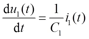
根據(jù)圖2,建立系統(tǒng)微分方程為


輸出方程為

其中

系統(tǒng)中包含三個(gè)非線性項(xiàng),分別是逆變器輸出電壓AB、整流橋輸入電壓CD和整流橋輸出直流電流rect,將其定義為


式中,當(dāng)s+0.25s(1-/p)≤s+0.25s(1+/p)時(shí),AB()=1;當(dāng)(+0.5)s+0.25s(1-/p)≤(+1)s-0.25s(1-/p)時(shí),AB()=-1;其余為0。當(dāng)s≤(+0.5)s時(shí),CD()=1,當(dāng)(+0.5)s≤(+1)s時(shí),CD()=-1。
取狀態(tài)變量()、輸入變量()和輸出變量()分別為


式(3)~式(10)所描述的系統(tǒng)是一個(gè)非線性時(shí)變不連續(xù)系統(tǒng),不便于進(jìn)行分析。使用本文提出的激活函數(shù)可以將其轉(zhuǎn)變?yōu)檫B續(xù)系統(tǒng)。
3 基于激活函數(shù)的LCC-S型WPT系統(tǒng)模型
3.1 開(kāi)環(huán)系統(tǒng)建模
逆變器輸出電壓波形如圖3所示。對(duì)于式(12)中AB,利用周期性激活函數(shù)可表示為


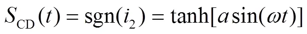
根據(jù)圖3所示的整流橋輸入電壓、輸入電流及輸出電流波形,整流橋輸入電壓CD取決于整流橋輸入電流2的方向。若2為正,則CD=o;若2為負(fù),則CD=-o,即CD= sgn(2)o。整流橋輸出電流是整流橋輸入電流的絕對(duì)值,可表示為|2|=2sgn(2)。對(duì)于式(13)中CD,利用周期激活函數(shù)可表示為
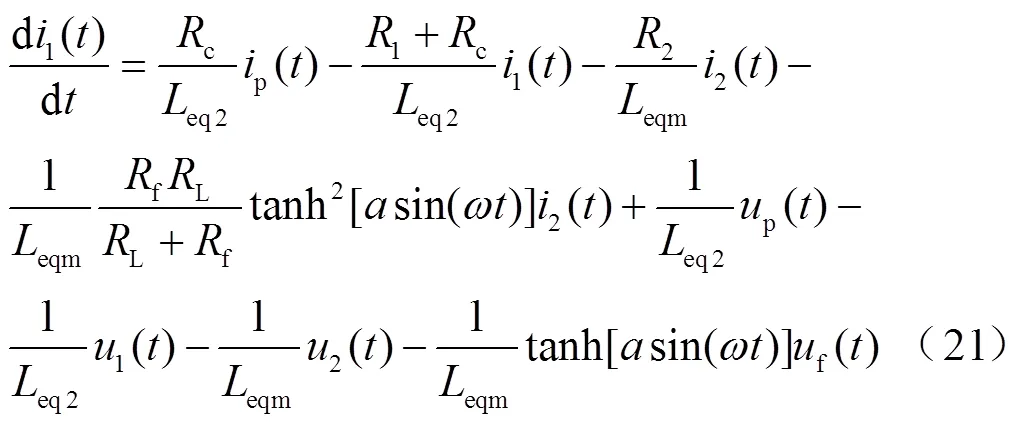
因此,LCC-S型WPT系統(tǒng)可以表示為一個(gè)統(tǒng)一的連續(xù)時(shí)間系統(tǒng)模型,即

輸出方程為

3.2 閉環(huán)系統(tǒng)建模
本文中,數(shù)字控制閉環(huán)系統(tǒng)框圖如圖4所示。

圖4 數(shù)字控制閉環(huán)系統(tǒng)框圖
對(duì)于積分環(huán)節(jié),將引入額外的狀態(tài)變量i,即

圖4中,PI()為PI控制器的傳遞函數(shù);p與i分別為PI控制器的比例與積分系數(shù),則PI控制器的輸出信號(hào)pre可表示為

在WPT系統(tǒng)中,不可避免地會(huì)引入延時(shí)環(huán)節(jié),主要包括硬件延時(shí)和數(shù)字控制器引入的采樣延時(shí)、計(jì)算延時(shí)及 PWM延時(shí)等。在本文中,硬件延時(shí)主要包括電壓檢測(cè)電路的延時(shí),MOSFET驅(qū)動(dòng)電路的延時(shí)以及MOSFET開(kāi)通與關(guān)斷的延時(shí),延時(shí)時(shí)間用d表示,實(shí)際測(cè)量d=87μs。


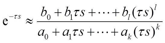
在本文中,采用Pade近似[25]以將延時(shí)環(huán)節(jié)表示為有限維多項(xiàng)式,即
利用傳遞函數(shù)實(shí)現(xiàn)問(wèn)題的一般性方法,可將式(32)轉(zhuǎn)換為式(33)~式(37)所示的等價(jià)微分方程,其中Pade近似的階數(shù)為5。


控制系統(tǒng)的輸出為

結(jié)合式(20)~式(38)即可得到描述整個(gè)LCC-S型WPT系統(tǒng)在閉環(huán)控制模式下的統(tǒng)一連續(xù)時(shí)間系統(tǒng)模型,此處不再具體給出。
4 仿真與實(shí)驗(yàn)驗(yàn)證
為了驗(yàn)證所建立的激活函數(shù)模型的準(zhǔn)確性,搭建系統(tǒng)仿真和實(shí)驗(yàn)平臺(tái),參數(shù)見(jiàn)表1,本文仿真和實(shí)驗(yàn)均采用此參數(shù)。
表1 LCC-S型WPT系統(tǒng)電路參數(shù)

Tab.1 The parameters of LCC-S compensation WPT system
在實(shí)驗(yàn)室中搭建系統(tǒng)實(shí)驗(yàn)樣機(jī),如圖5所示。實(shí)驗(yàn)樣機(jī)包括直流電源、全橋逆變器、LCC-S諧振網(wǎng)絡(luò)、全橋整流器和電子負(fù)載。

圖5 LCC-S型WPT系統(tǒng)實(shí)驗(yàn)樣機(jī)
4.1 穩(wěn)態(tài)模型驗(yàn)證
為了驗(yàn)證本文提出的基于激活函數(shù)的LCC-S型WPT系統(tǒng)模型的精確度,將激活函數(shù)模型與非線性時(shí)域仿真模型、EDF模型和GSSA模型的結(jié)果進(jìn)行對(duì)比,其中在Matlab/Simulink中實(shí)現(xiàn)了非線性時(shí)域仿真模型,然后通過(guò)使用Matlab中的m文件來(lái)執(zhí)行激活函數(shù)模型。LCC-S型WPT系統(tǒng)的激活函數(shù)模型中的陡度因子設(shè)置為1 000。LCC-S型WPT系統(tǒng)在不同負(fù)載下的電壓和電流仿真波形如圖6所示。圖6a中,=0.8π,L=10Ω,流入整流二極管的電流2處于連續(xù)模式;圖6b中,=0.8π,L=30Ω,流入整流二極管的電流2處于斷續(xù)模式。由圖6可以看出,EDF模型及GSSA模型在斷續(xù)模式下存在較大的誤差,而激活函數(shù)模型可以準(zhǔn)確地描述LCC-S型WPT系統(tǒng)的靜態(tài)特性。

4.2 大信號(hào)模型驗(yàn)證
為了進(jìn)一步驗(yàn)證3.1節(jié)中建立的激活函數(shù)模型,分別觀察在移相角擾動(dòng)和負(fù)載擾動(dòng)條件下系統(tǒng)的動(dòng)態(tài)響應(yīng)。對(duì)于移相角擾動(dòng),在=50ms時(shí),移相角從0.5π躍升至π,負(fù)載電阻L=10Ω。電感電流p、2和輸出電壓o的波形如圖7所示,實(shí)驗(yàn)結(jié)果如圖8所示。通過(guò)圖7可以看出,激活函數(shù)模型的穩(wěn)態(tài)和瞬態(tài)過(guò)程與Simulink電路仿真結(jié)果一致,同時(shí)與實(shí)驗(yàn)結(jié)果吻合。該結(jié)果表明,激活函數(shù)模型可以準(zhǔn)確地描述系統(tǒng)的瞬態(tài)特性。

圖7 移相角階躍時(shí)激活函數(shù)模型與仿真模型的對(duì)比

圖8 移相角階躍時(shí)實(shí)驗(yàn)波形
對(duì)于負(fù)載擾動(dòng),在=50ms時(shí),負(fù)載從10Ω躍升至30Ω,移相角保持0.8π。電感電流p、2和輸出電壓o的波形如圖9所示,實(shí)驗(yàn)結(jié)果如圖10所示。
由圖9可以看出,系統(tǒng)從連續(xù)模式轉(zhuǎn)換到斷續(xù)模式,激活函數(shù)模型的穩(wěn)態(tài)和瞬態(tài)過(guò)程與Simulink電路仿真結(jié)果一致,同時(shí)與實(shí)驗(yàn)結(jié)果吻合。該結(jié)果表明,激活函數(shù)模型可以準(zhǔn)確地描述系統(tǒng)的瞬態(tài)特性。

圖9 負(fù)載階躍時(shí)激活函數(shù)模型與仿真的對(duì)比

圖10 負(fù)載階躍時(shí)實(shí)驗(yàn)波形
綜上所述,激活函數(shù)模型、仿真和實(shí)驗(yàn)結(jié)果十分吻合,驗(yàn)證了本文建立的激活函數(shù)模型的準(zhǔn)確性。激活函數(shù)模型可以準(zhǔn)確地預(yù)測(cè)系統(tǒng)的穩(wěn)態(tài)和動(dòng)態(tài)過(guò)程,對(duì)WPT系統(tǒng)動(dòng)態(tài)性能分析,了解系統(tǒng)高速動(dòng)態(tài)變化的電壓電流應(yīng)力情況,系統(tǒng)參數(shù)設(shè)計(jì)起到輔助作用。
4.3 穩(wěn)定性驗(yàn)證
本節(jié)將利用3.2節(jié)建立的閉環(huán)模式下的激活函數(shù)模型進(jìn)行穩(wěn)定性分析,將模型計(jì)算結(jié)果與Simulink仿真結(jié)果和實(shí)驗(yàn)結(jié)果進(jìn)行對(duì)比,以探究系統(tǒng)存在的不穩(wěn)定現(xiàn)象。
首先,研究了控制器參數(shù)變化時(shí)所提出的激活函數(shù)模型和時(shí)域仿真模型中系統(tǒng)穩(wěn)定性的對(duì)比,結(jié)果如圖11所示。在這兩種模型中,延時(shí)時(shí)間d為87μs,i設(shè)置為10,<0.2s時(shí),p為0.11,=0.2s時(shí)p由0.11階躍至0.13。通過(guò)對(duì)比可以發(fā)現(xiàn),比例系數(shù)p增加,系統(tǒng)由穩(wěn)定狀態(tài)進(jìn)入不穩(wěn)定狀態(tài),出現(xiàn)低頻振蕩現(xiàn)象,同時(shí)激活函數(shù)模型和仿真模型具有相同的穩(wěn)態(tài)和瞬態(tài)響應(yīng)。對(duì)應(yīng)的實(shí)驗(yàn)波形如圖12所示,可以看出,激活函數(shù)模型、仿真模型和實(shí)驗(yàn)結(jié)果基本一致,證實(shí)了本文提出的激活函數(shù)模型的準(zhǔn)確性及穩(wěn)定性分析的有效性。

圖11 控制器參數(shù)階躍變化仿真波形(ki=10)
同理延時(shí)時(shí)間d為87μs,i=100,在=0.2s時(shí)將p由0.09階躍變化為0.11。此時(shí)激活函數(shù)模型和時(shí)域仿真模型中p和o的波形如圖13所示。實(shí)驗(yàn)波形如圖14所示。激活函數(shù)模型、仿真模型和實(shí)驗(yàn)結(jié)果基本一致。


圖13 控制器參數(shù)階躍變化仿真波形(ki =100)
由圖11和圖13可以發(fā)現(xiàn),在積分系數(shù)一定的情況下,比例系數(shù)的增大可能會(huì)導(dǎo)致系統(tǒng)失穩(wěn);對(duì)比圖11和圖13可以發(fā)現(xiàn),積分系數(shù)增加時(shí),系統(tǒng)保持穩(wěn)定狀態(tài)的比例系數(shù)的范圍減小。
為了驗(yàn)證負(fù)載對(duì)系統(tǒng)穩(wěn)定性的影響,進(jìn)行負(fù)載階躍實(shí)驗(yàn)。由圖11可知,系統(tǒng)運(yùn)行在p=0.13,i=10,L=10Ω的工況時(shí),系統(tǒng)處于不穩(wěn)定運(yùn)行狀態(tài)。在此條件下,負(fù)載電阻從10Ω階躍到7Ω,此時(shí)激活函數(shù)模型和仿真模型結(jié)果如圖15所示。二者具有相同的穩(wěn)態(tài)和瞬態(tài)響應(yīng)。結(jié)果表明,當(dāng)負(fù)載電阻減小,p和o由不穩(wěn)定狀態(tài)過(guò)渡到穩(wěn)定狀態(tài)。實(shí)驗(yàn)結(jié)果如圖16所示。因此,減小負(fù)載L可以增加系統(tǒng)的穩(wěn)定性。

圖14 控制器參數(shù)階躍變化實(shí)驗(yàn)波形(ki=100)

圖15 負(fù)載階躍變化仿真波形(ki=10)
本節(jié)激活函數(shù)模型、仿真模型和實(shí)驗(yàn)波形清楚地描繪了LCC-S型WPT系統(tǒng)的穩(wěn)態(tài)和動(dòng)態(tài)特性。當(dāng)系統(tǒng)進(jìn)入不穩(wěn)定狀態(tài)時(shí),發(fā)生低頻振蕩,此時(shí)系統(tǒng)中電壓和電流的幅值增大,這種現(xiàn)象會(huì)增加器件的應(yīng)力,甚至損壞器件。

圖16 負(fù)載階躍變化實(shí)驗(yàn)波形(ki=10)
5 結(jié)論
本文通過(guò)引入S型激活函數(shù),對(duì)不連續(xù)的開(kāi)關(guān)變量進(jìn)行連續(xù)處理,建立了LCC-S型WPT系統(tǒng)的大信號(hào)連續(xù)模型。所提出的模型具有以下優(yōu)點(diǎn):
1)利用激活函數(shù)建立的大信號(hào)模型不包括斷續(xù)函數(shù),例如符號(hào)函數(shù)、絕對(duì)值函數(shù)或方波。系統(tǒng)微分方程中的不連續(xù)函數(shù)由激活函數(shù)近似,以便使不連續(xù)部分連續(xù)。
2)該模型實(shí)現(xiàn)了對(duì)LCC-S型WPT系統(tǒng)的統(tǒng)一描述,以及對(duì)連續(xù)和斷續(xù)模式的統(tǒng)一描述。該模型準(zhǔn)確地描述了系統(tǒng)的穩(wěn)態(tài)和動(dòng)態(tài)特性。
3)通過(guò)建立的閉環(huán)模式下的激活函數(shù)模型,分析了控制器參數(shù)和系統(tǒng)參數(shù)對(duì)穩(wěn)定性的影響。
本文提出利用激活函數(shù)建立LCC-S型WPT系統(tǒng)的模型和穩(wěn)定性分析方法同樣適用于任何其他補(bǔ)償網(wǎng)絡(luò),可為系統(tǒng)參數(shù)和控制器參數(shù)設(shè)計(jì)提供指導(dǎo)。
[1] 沈棟, 杜貴平, 丘東元, 等. 無(wú)線電能傳輸系統(tǒng)電磁兼容研究現(xiàn)況及發(fā)展[J]. 電工技術(shù)學(xué)報(bào), 2020, 35(13): 2855-2869.
Shen Dong, Du Guiping, Qiu Dongyuan, et al. Research status and development trend of electromagnetic compatibility of wireless power transmission system[J]. Transactions of China Electrotecnical Society, 2020, 35(13): 2855-2869.
[2] 薛明, 楊慶新, 章鵬程, 等. 無(wú)線電能傳輸技術(shù)應(yīng)用研究現(xiàn)狀與關(guān)鍵問(wèn)題[J]. 電工技術(shù)學(xué)報(bào), 2021, 36(8): 1548-1567.
Xue Ming, Yang Qingxin, Zhang Pengcheng, et al. Application status and key issues of wireless power transmission technology[J]. Transactions of China Electrotecnical Society, 2021, 36(8): 1548-1567.
[3] 吳理豪, 張波. 電動(dòng)汽車(chē)靜態(tài)無(wú)線充電技術(shù)研究綜述(下篇)[J]. 電工技術(shù)學(xué)報(bào), 2020, 35(8): 1662-1678.
Wu Lihao, Zhang Bo. Overview of static wireless charging technology for electric vehicles: part Ⅱ[J]. Transactions of China Electrotecnical Society, 2020, 35(8): 1662-1678.
[4] Han Junfeng, Zhang Bo, Qiu Dongyuan, Bi-switching status modeling method for DC-DC converters in CCM and DCM operations[J]. IEEE Transactions on Power Electronics, 2017, 32(3): 2464-2472.
[5] Middlebrook R, Cuk S. A general unified approach to modelling switching power converter stages[C]//IEEE Power Electronics Specialists Conference, California, 1997: 18-34.
[6] 國(guó)玉剛, 崔納新. LCC-S 型無(wú)線電能傳輸系統(tǒng)優(yōu)化配置及特性研究[J].電工技術(shù)學(xué)報(bào), 2019, 34(18): 3723-3731.
Guo Yugang, Cui Naxin. Research on optimal configuration and characteristics based on LCC-S type wireless power transfer system[J]. Transactions of China Electrotecnical Society, 2019, 34(18): 3723-3731.
[7] Ramezani A, Shahrokh F, Hossein I, et al. Optimized LCC-series compensated resonant network for stationary wireless EV chargers[J]. IEEE Transactions on Industrial Electronics, 2019, 66(4): 2756-2765.
[8] Hu Aiguo Patrick. Modeling a contactless power supply using GSSA method[C]//2009 IEEE International Conference on Industrial Technology, Gippsland, VIC, 2009: 1-6.
[9] 程志遠(yuǎn), 邵會(huì)文, 陳坤, 等. 無(wú)線電能傳輸系統(tǒng)小信號(hào)模型降階研究[J]. 電工技術(shù)學(xué)報(bào), 2021, 36(24): 5143-5152.
Cheng Zhiyuan, Shao Huiwen, Chen Kun, et al. Research on order reduction of small signal model of wireless power transmission system[J]. Transactions of China Electrotecnical Society, 2021, 36(24): 5143-5152.
[10] Zahid Z, Zakariy D, Cong Z, et al. Modeling and control of series-series compensated inductive power transfer system[J]. IEEE Journal of Emerging and Selected Topics in Power Electronics, 2015, 3, (1): 111-123.
[11] Li Hongchang, Wang Kangping, Huang Lang, et al. Dynamic modeling based on coupled modes for wireless power transfer systems[J]. IEEE Transactions on Power Electronics, 2015, 30(11): 6245-625
[12] 高國(guó)慶, 雷萬(wàn)鈞, 袁曉杰, 等. 雙有源全橋變換器全狀態(tài)離散迭代建模與輸出電壓紋波分析[J]. 電工技術(shù)學(xué)報(bào), 2021, 36(2): 330-340.
Gao Guoqing,Lei Wanjun,Yuan Xiaojie,et al. Full-state discrete-time model and the output-voltage-ripple analysis of the dual active bridge converter[J]. Transactions of China Electrotecnical Society, 2021, 36(2): 330-340.
[13] Tahavorgar A, Quaicoe J. Stability and small signal analysis of the dual series-resonant DC-DC converter[J]. IEEE Transactions on Power Electronics, 2019, 34(2): 1420-1430.
[14] 張煥, 張慶, 于紀(jì)言. 激活函數(shù)的發(fā)展綜述及其性質(zhì)分析[J]. 西華大學(xué)學(xué)報(bào)(自然科學(xué)版), 2021, 40(4): 1-10.
Zhang Huan, Zhang Qing, Yu Jiyan. Overview of the development of activation function and its nature analysis[J]. Journal of Xihua University (Natural Science Edition), 2021, 40(4): 1-10.
[15] Lu Yimin, Huang Xianfeng, Huang Yizheng, et al. Sigmoid function model for a PFM power electronic converter[J]. IEEE Transactions on Power Electronics, 2020, 35(4): 4233-4241.
[16] Kim H, Son J, Lee J. A high-speed sliding-mode observer for the sensorless speed control of a PMSM[J]. IEEE Transactions on Industrial Electronics, 2011, 58(9): 4069-4077.
[17] Basterretxea K, Tarela J, del Campo I. Approximation of sigmoid function and the derivative for hardware implementation of artificial neurons[J]. IEEE Proceedings Circuits Devices and Systems, 2004, 151(1): 18-24.
[18] Richard J. Time-delay systems: an overview of some recent advances and open problems[J]. Automatica, 2003, 39(10): 1667-1694.
[19] Hu Jun, Wang Zidong, Gao Huijun, et al. Robust sliding mode control for discrete stochastic systems with mixed time delays, randomly occurring uncertainties, and randomly occurring nonlinearities[J]. IEEE Transactions on Industrial Electronics, 2012, 59(7): 3008-3015.
[20] Harnefors L, Antonopoulos A, Ilves K, et al. Global asymptotic stability of current-controlled modular multilevel converters[J]. IEEE Transactions on Power Electronics, 2015, 30(1): 249-258.
[21] 賈宏杰. 電力系統(tǒng)時(shí)滯穩(wěn)定性[M]. 北京: 科學(xué)出版社, 2016.
[22] 郭春義, 彭意, 徐李清, 等.考慮延時(shí)影響的 MMC-HVDC系統(tǒng)高頻振蕩機(jī)理分析[J]. 電力系統(tǒng)自動(dòng)化, 2020, 44(12): 119-126.
Guo Chunyi, Peng Yi, Xu Liqing, et al. Analysis on high-frequency oscillation mechanism for MMC-HVDC system considering influence of time delay[J]. Automation of Electric Power Systems, 2020, 44(12): 119-126.
[23] Dong Chaoyu, Yang Shunfeng, Jia Hongjie, et al. Padé-based stability analysis for a modular multilevel converter considering the time delay in the digital control system[J]. IEEE Transactions on Industrial Electronics, 2019, 66(7): 5242-5253.
[24] Li Hongyi, Wang Lijie, Du Haiping, et al. Adaptive fuzzy back stepping tracking control for strict-feedback systems with input delay[J]. IEEE Transactions on Fuzzy Systems, 2017, 25(3): 642-652.
[25] 陳錦洲,陳磊,陳亦平, 等. 基于Pade近似的電力系統(tǒng)頻率振蕩模式延時(shí)軌跡分析[J]. 電力系統(tǒng)自動(dòng)化, 2019, 43(14): 120-125.
Chen Jinzhou, Chen Lei, Chen Yiping, et al. Trajectory analysis of time delay for frequency oscillation mode of power system based on Pade approximation[J]. Automation of Electric Power Systems, 2019, 43(14): 120-125.
Modeling and Stability Analysis of Wireless Power Transfer System with an LCC-S Compensated Network Based on Activation Function
Hu Xiufang Wang Yue Lü Shuangqing Zhao Delin Ma Tianlu
(State Key Laboratory of Electrical Insulation and Power Equipment Xi’an Jiaotong University Xi’an 710049 China)
Wireless power transfer (WPT) system based on power electronic devices is a switching system, its large-signal model is the basis for studying the operating characteristics and stability of the system. The key to modeling is how to describe the nonlinear and discrete switch variables in the system. In this paper, a modeling method based on sigmoid activation function is proposed to solve this problem. Since the sigmoid activation function is continuous, smooth, differentiable, and saturated at a certain value. Therefore, a sigmoid activation function with a large steepness factor is used to approximate the switching process of the switch, the WPT system is transformed from a discrete switching system to a continuous system. An LCC-S compensated WPT system is selected as an example, and its sigmoid function model in open-loop and closed-loop mode is constructed. However, in closed-loop control mode, the time delay in digital control system is often ignored. Delay link makes WPT system more complicated. For systems without time delay, a certain mapping relationship can be established between input and output. But the existence of time delay may disturb this specific relationship. For the same sampled signal, the time delay in digital control system may lead to the instability of WPT system. The performance of WPT system will inevitably be affected or even deteriorated. Therefore, it is necessary to analyze the stability considering the influence of time delay.
In order to avoid these problems, approximating the time delay in stability analysis becomes a preferred solution. Time delay can be approximated by first-order lag, Taylor expansion, Pade approximation, etc. Compared with the first-order lag and Taylor series, Pade approximation has better performance because of its rational polynomial form. In addition, Pade approximation can handle a relatively short delay. Because the time delay of digital control system is in the order of microseconds, Pade approximation may be more appropriate. Based on the fifth-order pade equivalent approximate delay link, a closed-loop model is established to reveal the instability in the system. The influence of controller parameters and system parameters on transient behavior and stability are analyzed.
In addition, the simulation and experimental platform of the LCC-S compensated WPT system are built in this paper, and the simulation and experimental results verify the validity of the above-derived model. The large signal model established by activation function does not include discontinuous functions, such as sign function, absolute value function or square wave. The discontinuous function in the differential equation of the system is approximated by the activation function in order to make the discontinuous part continuous. From continuous mode to discontinuous mode, the steady and transient processes of the activation function model are consistent with the simulation results of simulation and the experimental results. The results show that the activation function model can accurately describe the transient characteristics of the system. The generalized state-space averaging (GSSA) and extended describing function (EDF) models which are commonly used in WPT systems are compared with model established by activation function, the results show that the model established by activation function model has higher accuracy.
When the system enters into an unstable state, low-frequency oscillation occurs. At this time, the amplitude of voltage and current in the system increases. This phenomenon will increase the stress of the device, or even damage the device. The activation function model, simulation model and experimental waveform in this section clearly describe the steady-state and dynamic characteristics of LCC-S compensation WPT system.
Wireless power transfer, LCC-S compensation topology, activation function, large signal model, stability
10.19595/j.cnki.1000-6753.tces.211722
TM724
2021-10-29
2022-01-05
胡秀芳 女,1986年生,博士研究生,研究方向?yàn)闊o(wú)線電能傳輸系統(tǒng)建模和控制。E-mail:huxiufang029@stu.xjtu.edu.cn
王 躍 男,1972年生,教授,博士生導(dǎo)師,研究方向?yàn)闊o(wú)線電能傳輸技術(shù)、雙有源全橋DC-DC變換器、模塊化多電平換流器、虛擬同步發(fā)電機(jī)。E-mail:davidwangyue@mail.xjtu.edu.cn(通信作者)
(編輯 赫 蕾)
猜你喜歡
童話王國(guó)·奇妙邏輯推理(2024年5期)2024-06-19 16:03:38
小獼猴智力畫(huà)刊(2022年9期)2022-11-04 02:31:42
工業(yè)設(shè)計(jì)(2022年8期)2022-09-09 07:43:20
軍民兩用技術(shù)與產(chǎn)品(2021年10期)2021-03-16 06:05:30
北京測(cè)繪(2020年12期)2020-12-29 01:33:58
中學(xué)生數(shù)理化·七年級(jí)數(shù)學(xué)人教版(2020年10期)2020-11-26 08:24:50
數(shù)學(xué)物理學(xué)報(bào)(2020年2期)2020-06-02 11:29:24
小哥白尼(趣味科學(xué))(2019年6期)2019-10-10 01:01:50
家庭影院技術(shù)(2017年9期)2017-09-26 03:41:45
光學(xué)精密工程(2016年6期)2016-11-07 09:07:19
