數字散斑干涉形變測量中基于多CCD的相位拼接
2022-05-07 03:31:30隆軍蔡萍潘淑媛劉持越閆浩
光子學報
2022年4期
關鍵詞:上海
隆軍,蔡萍,潘淑媛,劉持越,閆浩
(1 上海交通大學 電子信息與電氣工程學院,上海 200240)
(2 上海智能診療儀器工程技術研究中心,上海 200240)
0 Introduction
Digital Speckle Pattern Interferometry(DSPI)[1-2]provides an effective means of full-field and noncontact measurement of deformation or displacement. It has been widely used in material properties analysis[3-7],structural design verification[8],and thermal stress analysis[9]. With the advancement of the aerospace and automotive industry,deformation measurements with a large Field of View(FOV),high resolution and wide measurement range are becoming more and more urgent. The synthesis of multiple sub-holograms has proven effective in increasing the field of view and improving the lateral resolution of Digital Holography(DH)[10-12].
In the current DH aperture synthesis methods,sub-holograms are obtained by a multi-step image acquisition operation as the object or camera is scanned along thexandy-axis[10,12-15]. In the case where there is a certain overlap area between adjacent sub-holograms,the aperture synthesis algorithm can stitch all the subholograms by image registration to obtain a full-field hologram.This method assumes that two neighboring subholograms have the same intensity distribution in the overlapping region. It is only applicable to the measurement and observation of stationary objects. In DH or DSPI deformation measurements,two surface states of the object are involved,corresponding to before and after deformation,and the full-field deformation is obtained by subtracting the pre-deformation hologram or interferogram note from the post-deformation hologram or interferogram. Positioning errors in objects or cameras during successive sub-image acquisitions can lead to mismatches in the position of the corresponding pixels of the stitched image before and after the deformation,which may invalidate the resolved deformation. In addition,axial misalignment between corresponding hologram pairs will result in stitching failure[14,16].
The use of multiple CCDs to cover the full field of view can overcome the disadvantages of multi-step image acquisition schemes. However,the relative positions among the CCDs need to be addressed. Using multi-CCDs to cover the full field of view can overcome the drawback of the multi-step image acquisition scheme. However,the relative positions among CCDs need to be addressed. This is usually estimated by calculating the similarity of intensity images in overlapping regions between adjacent images[13-14,17-18]. However,the intensity distribution in the overlapping areas is usually unequal due to non-uniform illumination light,angular differences between the reference and object beams and differences in the CCD,which affects the correctness of the relative position estimation. Therefore,a method is proposed to estimate relative positions based on the consistency of unwrapped phase maps between adjacent CCDs. At the same time,phase deviations between sub-images of multiple CCDs in the overlapping area caused by the distinct phase reference points of sub-images can be compensated for. Additionally,multi-CCDs solutions pose the problem of bulky and uneconomical systems,so the size of the overlap region should be as small as possible.
To evaluate the effectiveness of image registration of multi-CCDs DSPI system,a dual-CCDs DSPI system was constructed,the relative positions between CCDs were estimated based on the unwrapped phase diagram,the effect of the size of the overlapping area on the image registration accuracy was analyzed,and a compensation method of the phase deviation between CCDs was proposed. Finally,the registration accuracy of the stitching method is evaluated with a calibrated artifact.
1 Method
The optical setup of the two CCD DSPI system is shown in Fig.1. The light source is a laser with a wavelength of 532 nm. A fiber optic coupler and beam splitter are used to split the laser beam into two beams,one of which serves as thereference light while the other is the illumination light,forminga,βangle with the optical axis of the CCDs(β=45° in our setup). The backscattered light from the object is collected by a lens with a focal length of 85 mm,which is approximately 96 mm from the CCD sensor. There is an aperture in front of the lens to reduce high high-frequency noise and to limit the size of the first-order spectrum in the Fourier transform domain. The reference and object beams are brought together by a 50∶50 beam combiner in front of the CCD sensor. Each CCD records the corresponding sub-speckle pattern and transmits it to the computer for sequential data processing. To improve the quality of the interferogram,an NDF is used to adjust the intensity ratio between the object beam and the reference beam. Note that the distance between NDF and the outlet of optical fiber should be as small as possible to avoid the influence of the NDF on the wavefront of reference wavefront.
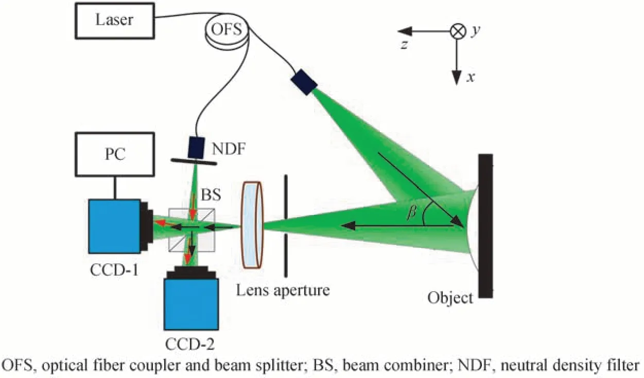
Fig.1 Multi-CCD DSPI experimental setup
The speckle interferograms beforeIb(x,y) and afterIa(x,y) the object surface deformation are recorded with each CCD,one of the interferograms obtained by CCD#1 and CCD#2 are shown in Fig.2(a)and(b),respectively. By using the Fourier-transform method[19],the phase differenceδ(x,y)caused by the deformation or displacement of the object surface is obtained. After noise suppression filtering[20]and phase unwrapping[21],the unwrapped phase maps(φp(x,y) andφq(x,y))of each CCD are obtained. The flow chart of proposed method of phase stitching is shown in Fig.2.
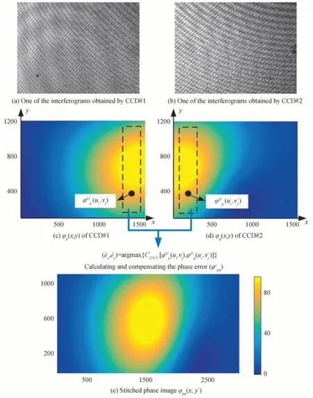
Fig.2 The flow chart of proposed method of phase stitching
After the unwrapped phase maps are obtained,shown as Fig. 2(c)and(d),assuming a set of relative positions(ex,ey),calculating the similarity between the phase(ui,vj) andof the overlapping area by Zero-Normalized Cross-Correlation(ZNCC)criterion[22].

where the overlapping area of the two unwrapped phases isI×Jpixels,=ui-ex=vj-ey(i∈[1,I],j∈[1,J]),vj) anddenote the phase value at coordinates (ui,vj) and (′) of the overlapping area of the CCD#1 and the CCD#2,respectively;andandare the mean values of the overlapping area of the CCD#1 and the CCD#2,respectively.
The ZNCC criterion defined in Eq.(1) is a parametric objective function involving two unknown parameters of the relative positions(ex,ey)of the two CCDs. Mathematically,this becomes a parametric optimization problem. The position corresponding to the maximum value of the objective function Eq.(1)is the best estimate of the relative position(). Then the phase error()between(ui,vj),in the overlapping area can be calculated by Eq.(2). Note that the relative position()between CCDs needs to be solved once,but the phase error()under different deformation values needs to be solved every time.

Then compensating the phase deviation between CCDs by Eq.(3)and

where(x,y) is the compensated phase map ofφq(x,y) . Then a larger unwrapped phase mapφpq(x′,y′)(x′∈[1,M+ex],∈[1,N-ey])can be correctly stitched,shown as Fig.2(e),and the deformationlw(x′,y′)can be calculated by Eq.(4).
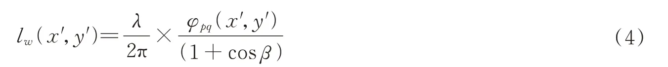
wherelw(x′,y′)is the out of plane deformation of the tested specimen,λis the wavelength of the laser,βis the included angle between illumination direction and detection direction.
2 Experiment and results
The experiment setup is shown in Fig. 3,where two CCDs with a pixel size of 4.4 μm ×4.4 μm and 1 600×1 200 pixels were utilized to record multiple sub-images. An artifact fixed to a calibrated loading device was employed to investigate the proposed method. The deformation is imposed by piezo actuators. The artifact is a disk shape. The displacement of the central area is calibrated with a universal length meter(HELIOSIP550M). It is often the case that one always expects the maximum field of view from as few CCDs as possible. Therefore,it is essential to explore the effect of overlap area size on the stitching results. Comparing the standard deviation of the difference in overlap area measurements before and after stitching different sizes of overlap areas,the results are shown in Fig. 4. The standard deviation is not sensitive to the size of the overlapping area,the smallest overlap area size in our experiments is 59 pixels and the largest size is 817 pixels in thex-axis direction. The maximum standard deviation is less than 0.018 μm and the minimum standard deviation is greater than 0.013 μm,and the difference between them is less than 0.005 μm which is neglibible.The standard deviation is less than 0.015 μm when the size of the overlap area is between 141 and 461 pixels,corresponding to a percentage of the overlap area between 8.8% and 28.8%. Therefore,when using multiple CCDs for phase stitching in the DSPI,it is appropriate to take an overlap area of around 10%.
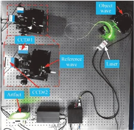
Fig.3 Experiment setup
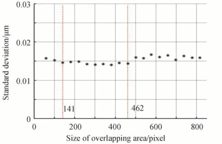
Fig.4 The relationship between the standard deviation of the difference of before and after stitching and size of overlapping area
In order to prove the effective of the proposed method,the relative error which is defined as
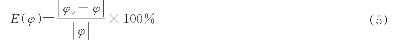
whereφoandφare the phases of the overlapping region before and after stitching,respectively. When the deformation of the workpiece is 9 μm the unwrapped phase and the relative error of the overlapping region before and after stitching are shown in Fig.5. The FOV expends from 5.5 cm×4 cm to 10 cm×4 cm after stitching. The maximum relative error before and after stitching is less than 1%,which illustrates the effectiveness of the proposed method.
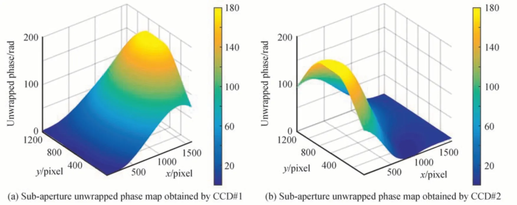
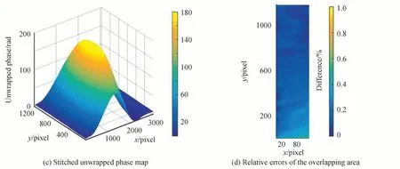
Fig.5 Unwrapped phase map and the relative errors of the overlapping area before and after stitching
To further evaluate the proposed method,a total of 9 displacement loading points are included,and three groups of values are measured by CCD#1,CCD#2,and the phase stitching method. The fitted curves and residual errors are shown in Fig.6. The Root Means Squared Errors(RMSE)and coefficient of determinationRare shown in Table 1. A good fit to a range of discrete deformation values using the Least Square(LS)method is shown in Fig.6(a)and is evaluated quantitatively using the metricRin Table 1. The measurement errors and fitting residuals are shown in Fig. 6(b)are small and illustrate the validity of the measurement method. By comparing the RMES values shown in Table 1,the measurements of the proposed method are more accurate than those of a single CCD. It seems to violate that the errors in stitching must be larger than the measurement of a single CCD. However,it should be noted that the values of the overlapping areas are averaged out during the stitching process,which may account for the lower mean square error of the sutures compared to the single CCD measurements.Maybe the random noise was suppressed during the averaging process.

Table 1 The RMSE and R of the measurement results
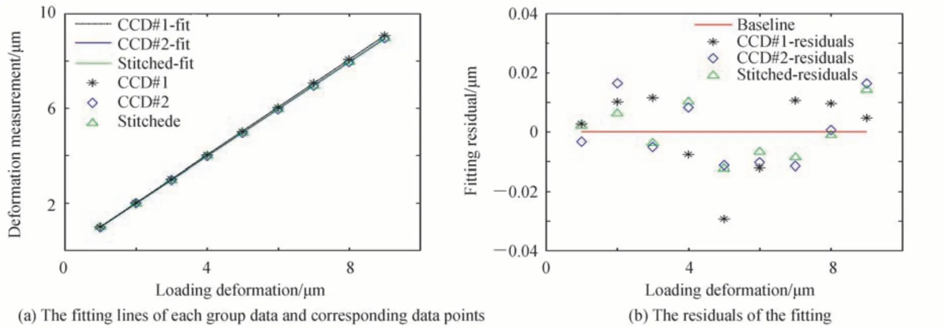
Fig.6 Least square fitting and fitting residuals
Based on the results obtained above,it can be concluded that phase stitching is effective and allows for FOV expansion.
3 Conclusion
A DSPI system with two CCDs is used to record multiple sub-aperture images to avoid scanning errors in the micro-positioning stage when moving the CCD or object. The registration positions were calibrated to eliminate phase errors between SASPIs. In order to obtain the maximum FOV with fewer CCDs,the relationship between the standard deviation and the size of the overlapping area was investigated. The size of the overlap zone is approximately 10%,which may be appropriate in terms of the trade-off between FOV and accuracy. To demonstrate the effectiveness of the phase stitching method,a calibrated loading device driven by a piezoelectric actuator was used. The measurement accuracy of the phase stitching method is approximate to that of the single-camera method when comparing the measurements of the calibration points by RMSE metric.Since the true value of the full field is unknown,the difference in overlap area between the single CCD method and the phase stitching method was calculated to evaluate the confidence of the full field values obtained by the proposed method,and these values are less than 1%. Furthermore,with more CCDs,the measurement range and axial resolution are increased to a certain FOV.
登錄APP查看全文
猜你喜歡
國家教育行政學院學報(2022年9期)2022-10-10 10:02:28
散文詩(2021年24期)2021-12-05 09:11:54
環境衛生工程(2021年5期)2021-11-20 05:45:36
少先隊活動(2021年5期)2021-07-22 09:00:02
環境衛生工程(2021年3期)2021-07-21 05:34:40
環境衛生工程(2021年2期)2021-06-09 09:11:16
家庭影院技術(2020年11期)2020-12-28 01:22:42
上海質量(2019年8期)2019-11-16 08:47:12
小主人報(2018年24期)2018-12-13 14:13:50
電器工業(2017年1期)2017-04-11 10:00:36
