Physical design of a new set of high poloidal mode number coils in the EAST tokamak
2022-04-15 05:13:32LiangLIAO廖亮YunfengLIANG梁云峰ShaochengLIU劉少承HuaxiangZHANG張華祥XiangJI戢翔YouwenSUN孫有文WenyinWEI魏文崟HuihuiWANG王輝輝JinpingQIAN錢金平LiangWANG王亮ManniJIA賈曼妮LongZENG曾龍XiangGAO高翔andtheEASTTeam
Plasma Science and Technology 2022年3期
Liang LIAO (廖亮), Yunfeng LIANG (梁云峰),Shaocheng LIU (劉少承), Huaxiang ZHANG (張華祥), Xiang JI (戢翔),Youwen SUN (孫有文), Wenyin WEI (魏文崟), Huihui WANG (王輝輝),Jinping QIAN (錢金平), Liang WANG (王亮), Manni JIA (賈曼妮),Long ZENG (曾龍), Xiang GAO (高翔) and the EAST Team
1 Institute of Plasma Physics, Hefei Institutes of Physical Science, Chinese Academy of Sciences, Hefei 230031, People’s Republic of China
2 University of Science and Technology of China, Hefei 230026, People’s Republic of China
3 Forschungszentrum Jülich GmbH, Institut für Energie- und Klimaforschung—Plasmaphysik, Partner of the Trilateral Euregio Cluster (TEC), Jülich D-52425, Germany
4 International Joint Research Laboratory of Magnetic Confinement Fusion and Plasma Physics,State Key Laboratory of Advanced Electromagnetic Engineering and Technology,School of Electrical and Electronic Engineering, Huazhong University of Science and Technology, Wuhan 430074, People’s Republic of China
Abstract An external resonant magnetic perturbation (RMP) field, which is an effective method to mitigate or suppress the edge localized mode(ELM),has been planned to be applied on the ELM control issue in ITER.A new set of magnetic perturbation coils,named as high m coils,has been developed for the EAST tokamak.The magnetic perturbation field of the high m coils is localized in the midplane of the low field side,with the spectral characteristic of high m and wide n, where m and n are the poloidal and toroidal mode numbers, respectively.The high m coils generate a strong localized perturbation field.Edge magnetic topology under the application of high m coils should have either a small or no stochastic region.With the combination of the high m coils and the current RMP coils in the EAST, flexible working scenarios of the magnetic perturbation field are available, which is beneficial for ELM control exploration on EAST.Numerical simulations have been carried out to characterize the high m coil system, including the magnetic spectrum and magnetic topology, which shows a great flexibility of magnetic perturbation variation as a tool to investigate the interaction between ELM and external magnetic perturbation.
Keywords: resonant magnetic perturbation, ELM control, tokamak
1.Introduction
A great breakthrough in fusion research is the improved confinement operational modes in tokamaks.The well-known high confinement mode (H-mode) was first discovered on ASDEX in 1982 [1].Compared with low confinement mode(L-mode),the triple product required by the Lawson criterion can be increased by two orders of magnitude in an H-mode discharge [2].However, edge localized modes (ELMs), and strong magnetohydrodynamic (MHD) instabilities, are commonly found accompanying H-mode operation in tokamaks.During the eruption of ELMs, a large amount of heat and particles in the core plasmas is exhausted into the scrape-off layer (SOL) and deposited on the divertor targets, which could induce an extremely high heat load on the target and lead to strong sputtering and erosion of material,especially in ITER and the future fusion reactors [3–5].External resonant magnetic perturbation (RMP) fields have been demonstrated to be an effective method to suppress or mitigate ELMs in various tokamaks, such as DIII-D [6], JET [7], ASDEX Upgrade [8], KSTAR [9], and EAST [10].Consequently,RMP is a key technique to control ELMs and ELM induced divertor heat load,so that RMP coils will be installed in ITER[11].Based on the experimental and modelling works in the last decade,a possible mechanism of ELM control induced by RMP is proposed as follows: magnetic islands would be formed on the rational surfaces at the plasma edge under the application of RMPs, and the overlap of these neighboring islands could create a stochastic region,which would enhance the effective radial transport of heat and particle, and consequently reduce the pedestal pressure and avoid the triggering of type-I ELMs [11, 12].
By now, major devices have achieved ELM mitigation and suppression within differentq95windows [6, 7].The dominant toroidal perturbation mode of these experiments is mostly less than 4.ELM mitigation and suppression have been achieved in EAST by using its up-down symmetrical RMP coil system which generates toroidal magnetic perturbation mostly withn≤4 [13,14].When low order magnetic perturbation is used to control ELMs, due to its large amplitude and deep penetration depth, it can have substantial impact on core MHD instabilities and particle transport,potentially forming a locked mode in the core [15], and thereby causing plasma confinement degradation and density pump-out [16, 17].In the DIII-D experiment, the decreased coil current threshold of ELM suppression suggests that mixed toroidal harmonic RMPs offer a better path to ELM control [18].Therefore, it is worthy of attention to study the influence of external resonant magnetic perturbations with high order modes and multiple modes on the plasma, especially the influence on ELM behavior.
To achieve ELM suppression without obvious impact on the core plasma and confinement degradation, a new type of magnetic perturbation coil, named high m coils, has been designed for EAST.It would generate a strongly localized perturbation field.To avoid confusion, in this work the acronym ‘RMP’ will not be used to describe high m coils.Compared with the RMP system in EAST, the high m coils are capable to create high m and wide n magnetic perturbations,which have better coupling at poloidal structure,such as ballooning modes with high order structures.The conceptual design of the high m coils is introduced in section 2.Its magnetic field features are described in section 3.The synergy between the EAST RMP and high m coils is presented in section 4.Finally, a summary and outlooks are given in section 5.
2.Conceptual design
In recent years, some experimental results indicate that the spatial structure of ELMs has the characteristics of high poloidal (m>20) and medium toroidal mode numbers(3≤n≤ 20)[19,20].Modelling research also confirms that the toroidal mode number of the most unstable modes increases when going from current- to pressure gradient-driven-boundaries.Therefore, the variation of toroidal mode number along the stability threshold plays an important role in the peeling-ballooning instability [21, 22].The high m components of magnetic perturbations generated by lower-hybridwave (LHW)-induced helical currents play an important role in the ELM mitigation on EAST[23].However,some results suggest that the magnetic resonance is not a strictly necessary condition to achieve ELM mitigation by using external field perturbations [22].The influence of RMPs on the mode coupling and saturation can be quite significant with small magnetic perturbations(about 10-5T)[24].Inspired by these previous research works, a new type of coil is being developed in EAST, which has smaller dominant Fourier components, but a strongly localized field.Compared with the current RMP system in EAST, the high m coils have a better resonance at high order modes, especially for the ballooning mode with a high n structure.The difficulty of engineering implementation is also taken into consideration.
As illustrated in figure 1,the high m coil system consists of two coils,which are located at the low field side(LFS)and are up-down symmetric about the outer midplane in the vacuum vessel.With this setup,the high m coil system is close to the last closed flux surface (LCFS) and is able to create a localized perturbation field with the same strength as the EAST RMP coils, though it is challenging to install the coils in a narrow space between two neighboring ports.Each coil is composed of two loops of a rounded rectangle shape (181.8 mm ×200 mm,201.7 mm×200 mm,poloidal×toroidal).As shown in figure 1(c), a single loop forms two circles with opposite current directions,i.e.the magnetic fields B1and B2generated by the two circles of the upper loop are directed inward and outward radially, respectively.Note that each coil has two turns to enhance the perturbation field.The direction of the current flowing in a single loop can be adjusted according to the preferred magnetic perturbation spectrum and experimental purpose.In this paper,the direction of the perturbation magnetic field is defined as below:positive(+)isBrpointing inward radially, while negative (-) isBrpointing outward radially.Consequently, there are two operation modes of a high m coils.The primary operation mode is presented in figure 1(c), with the directions of perturbation fieldas‘+ -+-’ corresponding to the four circles from top to bottom.Besides,the secondary operation mode has a distribution of perturbation field‘+--+’.
3.External magnetic perturbation fields induced by the high m coils
The magnetic field in the vacuum vessel generated by a high m coils has been calculated and analyzed by the ERGOS code[25] without considering the plasma response.The thickness of coils has also been neglected because the distance between plasma and coils is much larger than the thickness of the coils.
Compared with the toroidal and poloidal perturbation components, the radial perturbation field on the flux surface with a normalized radiusρ= 0.95 draws more interest in the ELM control.In figures 2(a) and (b), the magnetic spectra of the perturbation fieldBr/Btat the 95% normalized flux surface generated by the high m coils are illustrated for the primary operation mode ‘+ -+-’ and the secondary operation mode ‘+ - - +’, with 3 kA coil current.For comparison,an example of a n=1 EAST RMP configuration with maximum coil current 2.5 kA by which ELM suppression has been achieved in the previous EAST experiment[13]is given in figure 2(c).It can be seen that: (1) the dominant component(Brn,m)of a single set of high m coils is two orders of magnitude smaller than that of the EAST RMP coils, withBrn,m/Bt≈10-5.This is becauseBrn,mis an average effect on the entire flux surface and the total area of the EAST RMP coils is about two orders of magnitude larger than high m coils.However, owing to the strong localized perturbation field and the broad magnetic perturbation spectrum in both m and n dependence of high m coils,which will be introduced in the following part, abilities to affect edge instabilities is promising; (2) for ‘+ -+-’ operation mode in figure 2(a),the amplitudesBrn,m/Btretain 90% of then=1 component whennreaches 10,and remain still above 60%whenncomes to 20, exhibiting a very broad toroidal mode spectrum.Additionally, a double-peak structure appears in the poloidal mode number space, with the major peak located at m=15;(3)for‘+--+’operation mode in figure 2(b),the broad n spectrum characteristic and double-peak m structure are also observed, but the major peak in the poloidal mode space is shifted down to m=8; (4) the dominant componentsBrn,m/Btin the EAST RMP case are concentrated in the low m and n space compared with the high m coils.With the synergy of the high m coils and the EAST RMP coils, it is capable to create a perturbation field spectrum with considerable intensity covering a wide poloidal mode number regime.
Figures 3(a)–(c) show the 2D contour plots of the radial perturbation fieldBron theρ= 0.95 flux surface for the primary operation mode ‘+ -+-’, secondary operation mode‘+--+’of high m coils and the n=1 RMP coils in upper single null (USN) plasmas on EAST.Solid black lines represent typical EAST equilibrium magnetic field lines(q95=3.9)on the ρ=0.95 flux surface.As can be seen, the radial perturbation field generated by the high m coils occupies a very small area on theρ= 0.95 flux surface,localized in the LFS midplane where edge instabilities often occur.On theρ= 0.95 flux surface, localized maximum radial field strength of high m coils is larger than that of the EAST RMP.The sectional view of the radial perturbation field originated from high m coils and the EAST RMP coils are shown in figures 3(d)–(f).It should be noted that the intensive radial perturbation field densityBrof both primary operation mode(+ -+-) and secondary operation mode (+ - - +) is localized at the edge plasma.The maximum radial perturbation field strength of high m coils is 120 Gs at the LCFS, as shown in figures 3(d) and (e), while for EAST RMP it is 90 Gs.It is reasonable mainly because the distance between high m coils and the LCFS is smaller than the EAST RMP’s,although the number of turns of the EAST RMP is twice that of high m coils.In the case above, the shortest distance between the LCFS and high m coils is approximately 10 cm,and for the EAST RMP it is nearly 20 cm.
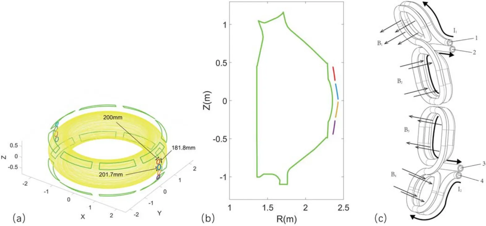
Figure 1.(a)3D view of the EAST tokamak torus,the EAST RMPs are shown in green and high m coils are located at the outer midplane;(b)layout of a high m coils in the poloidal cross-section;(c)sketch of a high m coils,and the current flowing directions and perturbation field Br of the primary operation mode.
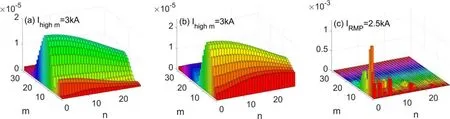
Figure 2.Magnetic spectrum of the perturbation field Br /Bt at the 95%normalized poloidal flux surface.(a)Primary operation mode of high m coils, (b) secondary operation mode of high m coils, (c) n=1 EAST RMP configuration.

Figure 3.2D contour plot of the radial perturbation field ( Gs)on theρ = 0.95 flux surface: (a) primary operation mode ‘+ -+-’ of 3 kA high m coils, (b) secondary operation mode ‘+ - - +’ of 3 kA high m coils, (c) 2.5 kA EAST RMP, n=1.Sectional view of the radial perturbation field( Gs) :(d)primary operation mode‘+-+-’of 3 kA high m coils,(e)secondary operation mode‘+--+’of 3 kA high m coils, (f) 2.5 kA EAST RMP, n=1.
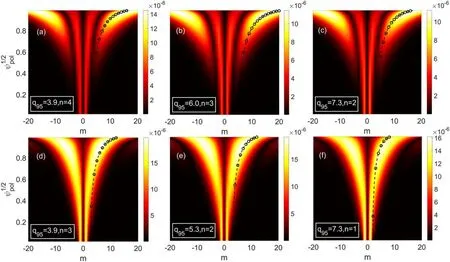
Figure 4.Radial profile of the vacuum radial perturbation field spectrum in the PEST flux coordinates: (a) n =4,=3.9,(b) n =3,=6.0and (c), n =2,=7.3for the primary operation mode with coil current=3 kA; and (d) n =3,=3.9,(e) n =2,=5.3and (f) n =1,=7.3for the secondary operation mode with coil current=3kA.Dashed curves indicate the resonant condition m=nq(r).Small circles on the m=nq(r) curves represent the locations of rational surfaces.
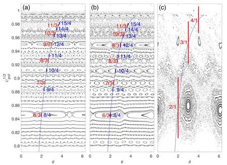
Figure 5.Poincaréplotinfulxcoordinates:(a)primaryoperationmodeofhighmcoils,(b)secondaryoperationmodewithcoilcurrent=3kA(EFIT equilibrium data of shot 41985 on EAST is used as the initial two-dimensional equilibrium)and(c)n=1 EAST RMP with coil current=2.5kA.
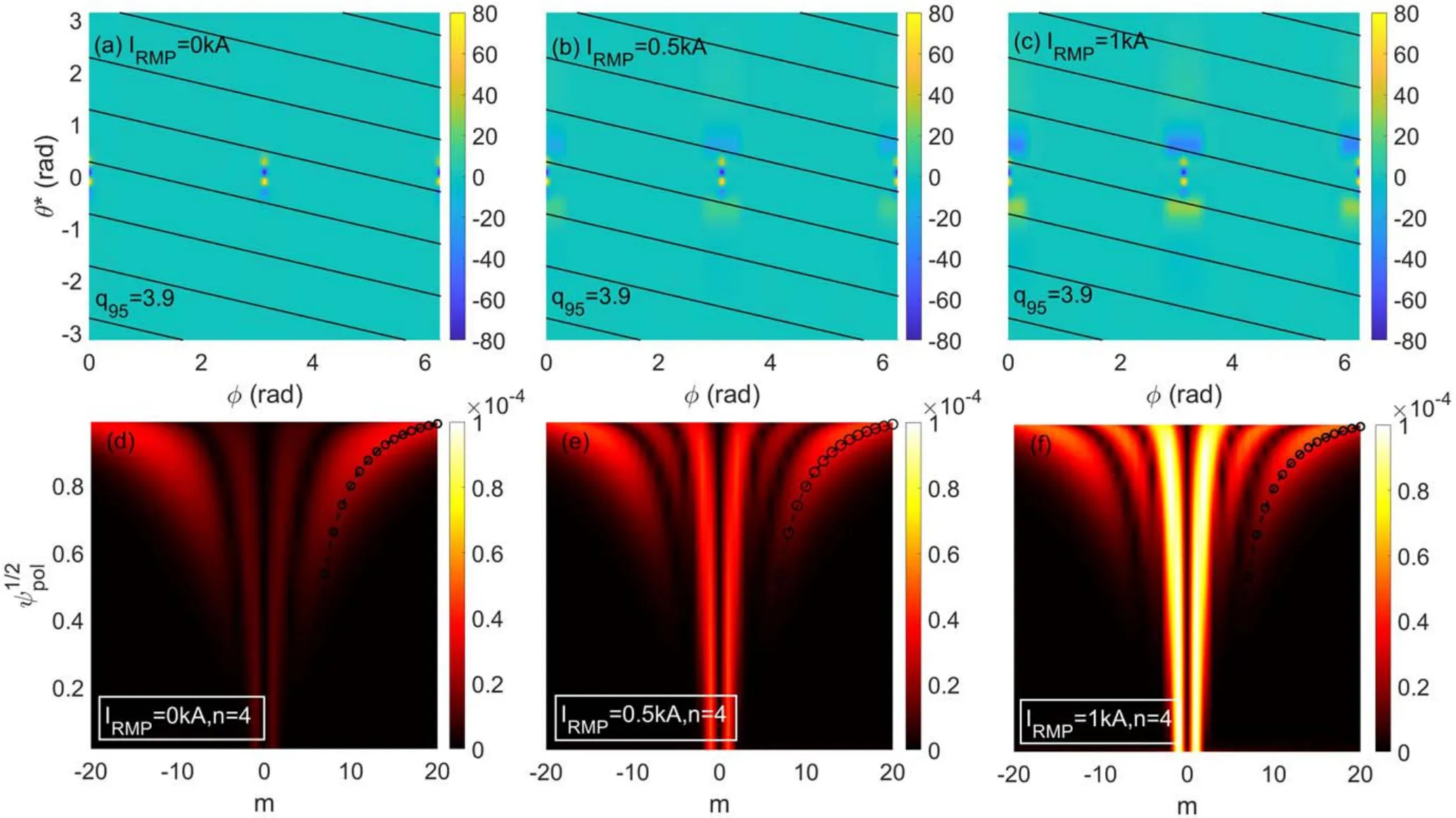
Figure 6.2D contour plot of the radial perturbation field ( Gs)on theρ = 0.95 flux surface for the synergy of high m coils(=3kA)and EAST RMP coils: (a)=0kA, (b)=0.5kA, (c)=1kA.The corresponding radial profile spectra of the vacuum perturbation field in the PEST flux coordinates for the n =4 component:(d)=0kA,(e)=0.5kA,(f)=1kA.The dashed curves indicate the resonant condition m = nq ( r ).Small circles on the m = nq ( r )curves represent the locations of the rational surfaces.
The radial profiles of the vacuum radial perturbation field spectrum in the PEST flux coordinates for the primary operation mode and secondary operation mode at different q profiles are shown in figure 4.The dashed curves indicate the resonance condition m=nq(r).Small circles on the m=nq(r) curves represent the locations of the rational surfaces.In an extremely broad range of the edge safety factor q95, from 3.9 to 7.3, for different toroidal mode number, the m=nq(r)curves lie on the ridge of perturbation spectrum of the high m coils for various toroidal mode numbers.Due to the broad toroidal mode spectrum characteristic of high m coils,amplitudes of the perturbation spectrum for these broad toroidal mode numbers are mostly the same order(Brn,m/Bt~10-5).The good resonance within a wide q95range at the plasma edge indicates a wider q95window for ELM suppression or mitigation by high m coils.When the operation mode of high m coils changes from the primary one to the secondary one, the major ridge of the radial perturbation spectrum is shifted down fromρ= 0.95 toρ= 0.9,because the penetration depth of the radial perturbation field in the secondary case is deeper than that in the primary case.An additional reason lies in the m=1 component in the core region being much stronger in the secondary operation mode.
The Poincaré plots in the flux coordinate under the primary and secondary operation modes of high m coils are shown in figure 5.For comparison, a Poincaré plot of the n=1 EAST RMP ELM suppression case in EAST [13] is given.The q profile (solid line) and the analytic islands widths(lengths of the line segments)are superimposed in the figure.The magnetic topology under the application of high m coils is obviously different from that generated by the EAST RMP: (1) the magnetic islands of different toroidal mode numbers are generated by the application of the high m coils;(2) the islands’ widths under the application of high m coils are significantly smaller than that of the EAST RMP, but the number of island chains in high m coils case is larger.The radial distance between two adjacent island chains is also smaller; (3) magnetic islands marked on the figures do not overlap under the application of high m coils.For the EAST RMP, magnetic islands overlap at the plasma edge(ρ>0.95), stochastic field lines are produced.In other cases while q95is above 4, overlapping of the magnetic islands at the edge can occur when high m coils are switched on.
4.Synergy between the EAST RMP and high m coils
To provide reliable operation at the required prolongation,an in-vessel RMP coil system has been proposed for ITER for the purposes of ELM control, increased vertical stability and stabilization of resistive wall modes [26].Currently, the KSTAR tokamak is the only major tokamak featuring invessel mid-plane RMP coils,whose configuration is similar to that of the planned ITER RMP coils [27], unlike other tokamaks equipped with two (top/bottom) rows of RMP coils.With these in-vessel mid-plane RMP coils, ELM changes were observed to differ (including suppression, mitigation)from phasing and field spectrum of RMPs in KSTAR[9,28].It was also found that the divertor heat fluxes near the outer strike point were broadened under the application of midplane RMP in KSTAR while the other two-row RMPs rarely affected the near-SOL heat flux[29].To explore the potential synergy effect between RMP coils and high m coils, the 2D contour plot of the radial perturbation field on theρ= 0.95 flux surface and the corresponding perturbation spectra under the synergy of high m coils (Ihighm=3kA) and RMP coils are shown in figure 6.By the application of EAST RMP coils installed at same toroidal position of high m coils, (1) the maximum amplitude of perturbation spectrum increases by over 20%, (2) an m=1 mode arises at the edge, mixed harmonics of all high m, medium m and low m modes are obtained.
Figure 7 shows the Poincaré plot, q profile and island widths in the flux coordinate under the simultaneous operation of high m coils and EAST RMP coils with the high m coil current kept at 3 kA and the RMP coil current increasing from 0 to 1 kA at intervals of 0.5 kA.For better understanding,here only the positions and widths of then= 2, 4 magnetic islands are plotted at the edge as an example.It can be seen that (1) the edge magnetic topology is changed due to the formation of magnetic island chains at different rational surfaces, (2) the overlapping of magnetic islands is observed at the very edge (ρ>0.96) of plasma with two sets of high m coils, and (3) the synergy of the high m coils and the EAST RMP coils makes it more flexible to actively control the radial distribution of the stochastication area.
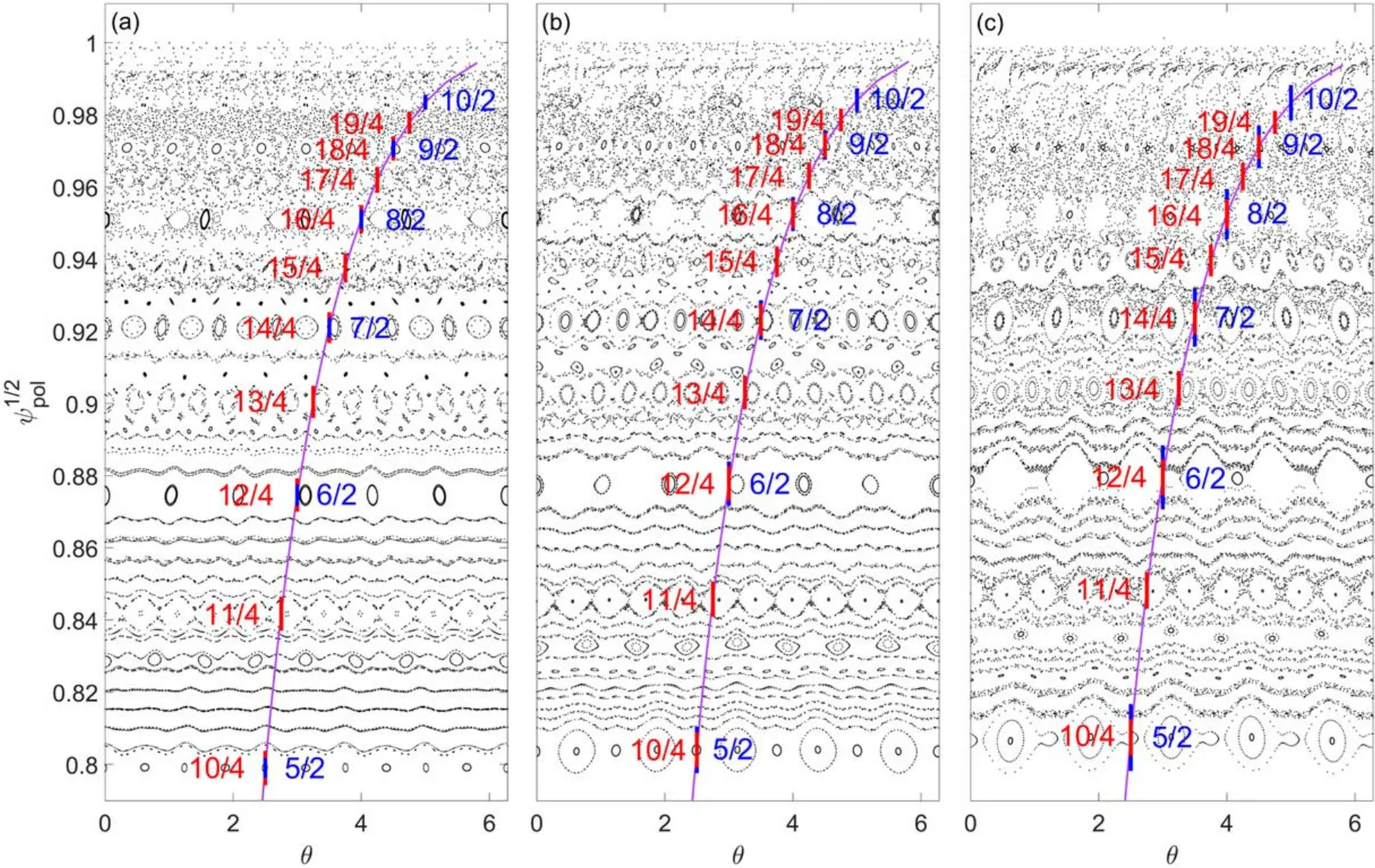
Figure 7.Poincaré plot in the flux coordinate under the synergy of the high m coils and the EAST RMP coils.The high m coils are operated in the primary mode with current=3kA,and RMP coil current is:(a)0 kA,(b)0.5 kA and(c)1 kA.The EFIT equilibrium of discharge 72999 of the EAST is used as the initial two-dimensional equilibrium.The n =2, 4 magnetic islands are marked in red and blue respectively.Here the width of island represents the length of line segment.
5.Summary and discussion
A new high m coil system located at the outer midplane has been designed for the EAST tokamak.The two most prominent characteristics of the high m coils are that: (1) the perturbation field localized in the midplane and plasma edge;(2)the dominant components of the radial perturbation field concentrated in the high m regime, with its peak around m=15 or 8 depending on the operation modes.In addition,the dominant component ofBrreveals a wide distribution in the toroidal mode number space,with a small decreasing rate when n<10.The perturbation magnetic field generated by the high m coils has been calculated, showing a good resonance at a wide range ofq95.Poincaré plot shows that under the application of high m coils, magnetic islands of multiple toroidal modes can be generated by the high m coils.All these simulations are based on the vacuum paradigm because the coupling of multiple toroidal modes,which is one of the main features of high m coils, is not yet accomplished currently in the ideal MHD codes,such as MARS-F.It should be pointed out that plasma response in different scenarios will not be the same.
Investigations of the potential joint operation of the new high m coils and the EAST RMP coils have also been performed.By turning on the EAST RMP coils at the same toroidal position as the high m coils, an enhancement of the high m components and mixed harmonic of both high order and low order modes can be obtained.Poincaré plots show that the width of the low n magnetic island increases under the application of the EAST RMP coils.This could be helpful to ELM mitigation or suppression with the threshold currents of high m coils.
Currently, the coils are being manufactured and will be installed in this year.Three types of power supply waveforms are considered, including sine wave, square wave and direct current.In the succeeding experiments, the plasma response process under the high m magnetic perturbation field and the influence of the strong localized magnetic perturbation field on plasma stability and edge transport properties will be investigated.
Acknowledgments
This work was supported by National Magnetic Confined Fusion Energy R&D Program of China (Nos.2017YFE0301100,2019YFE03040000 and 2017YFE0301300), National Natural Science Foundation of China (No.11875294), the Science Foundation of Institute of Plasma Physics, Chinese Academy of Sciences (No.DSJJ-2021-01) and the Collaborative Innovation Program of Hefei Science Center,CAS(No.2021HSC-CIP019).
 Plasma Science and Technology2022年3期
- Plasma Science and Technology的其它文章
- Design and preliminary test of a 105/140 GHz dual-frequency MW-level gyrotron
- Competitive effect between roughness and mask pattern on charging phenomena during plasma etching
- Reliability improvement of gas discharge tube by suppressing the formation of shortcircuit pathways
- A novel flexible plasma array for large-area uniform treatment of an irregular surface
- Pulsed high-current discharge in water:adiabatic model of expanding plasma channel and acoustic wave
- Comparison of double layer in argon helicon plasma and magnetized DC discharge plasma