Analysis on the Bonding Failure Mechanism of High Modulus Carbon Fiber Composites
2022-03-12 13:29:26LIANGYanminZUQingmingLIANGXuhaoYEZhoujunSHIWenfengLIZongzhouDONGBinJIANGHao
上海航天 2022年1期
LIANG Yanmin,ZU Qingming,LIANG Xuhao,YE Zhoujun,SHI Wenfeng,LI Zongzhou,DONG Bin,JIANG Hao
(1.Shanghai Composite Technology Co.,Ltd.,Shanghai 201112,China;2.Shanghai Aerospace Resin?based Composite Engineering Technology&Research Center,Shanghai 201112,China;3.Shanghai Academy of Spaceflight Technology,Shanghai 201109,China;4.Shanghai Spaceflight Precision Machinery Institute,Shanghai 201600,China;5.Department of Engineering Mechanics,Dalian University of Technology,Dalian 116024,Liaoning,China)
Abstract:In order to explore the bonding failure mechanism of high modulus carbon fiber composite materials,the tensile experiment and finite element numerical simulation for single-lap and bevel-lap joints of unidirectional laminates are carried out,and the stress distributions,the failure modes,and the damage contours are analyzed.The analysis shows that the main reason for the failure of the single-lap joint is that the stress concentration of the ply adjacent to the adhesive layer is serious owing to the modulus difference,and the stress cannot be effectively transmitted along the thickness direction of the laminate.When the tensile stress of the ply exceeds its ultimate strength in the loading process,the surface fiber will fail.Compared with the single-lap joint,the bevel-lap joint optimizes the stress transfer path along the thickness direction,allows each layer of the laminate to share the load,avoids the stress concentration of the surface layer,and improves the bearing capacity of the bevel-lap joint.The improved bearing capacity of the bevellap joint is twice as much as that of the single-lap joint.The research in this paper provides a new idea for the subsequent study of mechanical properties of adhesively bonded composite materials.
Key words:high modulus carbon fiber composite material;single-lap joint;bevel-lap joint;failure mode;numerical simulation;stress concentration;stress transfer
0 Introduction
Carbon fiber composite materials have many ad?vantages,such as light weight,high specific strength and specific modulus,corrosion resistance,fatigue resistance,designable structure,and easy integral forming,and can meet the requirements of the high structural efficiency of aerospace structures and easily obtain dimensionally stable structures.Therefore,composite materials,together with aluminum alloy,titanium alloy,and alloy steel,have become four ma?jor structural materials in the aerospace field.With the development of carbon fiber and its molding tech?nology,high modulus carbon fiber composites have become the main material for spacecraft structures,and have been widely used in satellite structures,pre?cision support components,and space mirrors.
With the development of the composites manu?facturing technology,the integrated molding technol?ogy is constantly improving,but the connection is still essential,and the structural connection part usu?ally becomes the weakness of the whole structure.Due to the brittleness and anisotropic characteristics of composite materials,the failure modes of compos?ite joints are various and the joint strength is com?plex.The common joint methods of composite mate?rials include mechanical joint,adhesive joint,stitching joint,Z-pin joint,and hybrid joint.
Adhesive bonding is a common way to connect composite materials,by which the composite parts are connected through adhesives.Its main advantages are that it can avoid the local stress concentration caused by mechanical connection,has good sealing,vibration damping,and insulation properties,can ob?tain smooth aerodynamic shape,and has no galvanic corrosion problem when connecting different materi?als.Compared with the mechanical connection,the adhesive bonding has the advantages of greater corro?sion resistance,lighter connection weight,higher connection efficiency,no damage to the composite materials,and better fatigue resistance effect.It has become one of the important development directions and branches of the lightweight and high-strength connection technology,and has been widely used in engineering.
Many scholars and experts have studied the bonding properties and failure modes of composite materials.By experimental test,theoretical calcula?tion,and simulation analysis,the effects of different stacking sequences,lap lengths,and adhesive layer thicknesses on the bonding properties are analyzed through the analysis of the adhesive layer stress.MAO et al.investigated the effects of different lap lengths and stacking sequences on the bonding strength and damage behaviors for adhesively bonded joints with single-lap and double-lap configurations.LIANG et al.studied the failure modes and ulti?mate loads of single-lap joints with different parame?ters such as the single-lap length and the adherend thickness.YE et al.established a mechanical mod?el for the single-lap joint of composite materials,and analyzed the distributions of shear stress and peel stress on the adhesive layer by loading the estimated load based on the beam bending theory.GUO et al.studied the effects of the lap length of singlelap composite joints on the tensile properties with re?spect to the stress distribution and the failure mode by finite element simulation.YUAN et al.studied the mechanism of the layer thickness on the bearing capacity of adhesive bonding joints through experi?ment,finite element simulation,and theoretic analy?sis.ZHANGproposed an improved theoretical so?lution for analyzing the shear stress of adhesively bonded single-lap and double-lap joints,assuming that shear strain only existed in the half-thickness of the adhesive layer.LIU et al.created the modified semi-analytical method for the adhesive layer stress of composite bevel-lap joints by applying the concept of differential and rule of composite ply stiffness dis?tribution.
At the same time,many studieshave shown that the ply adjacent to the adhesive layer are prone to failure,but there is no in-depth analysis of the fail?ure mechanism.In order to explore the failure mecha?nism of the ply adjacent to the adhesive of high modu?lus carbon fiber reinforced composites,the tensile ex?periment and finite element numerical simulation for the single-lap and bevel-lap joints of a unidirectional laminates are carried out,and the stress distribu?tions,the failure modes,and the damage contours are analyzed.The mechanism of the adhesive shear failure of the composite materials is explained from another point of view,which provides a new idea for the subsequent study of the mechanical properties of composite materials.
1 Experiments
1.1 Preparation and test
The carbon fiber/epoxy composite laminates are prepared,in which the fiber is the M55J grade high modulus carbon fiber,and the resin is the self-made A01 epoxy resin.The laminates are formed by the lay-up autoclave process with prepreg,the thickness of single layer prepreg is 0.1 mm,the lay-up mode is[0],and the thicknesses of the laminates are 2 mm.The laminates are cut into the adherends with a basic size of 100 mm×25 mm×2 mm.
There are two groups of joints with different structures,i.e.,single-lap joint(see Fig.1(a))and bevel-lap joint(see Fig.1(b)).The adhesive layer material is J133,which is a room-temperature curing liquid adhesive.During the bonding process,surface treatment is performed,and the thickness of the ad?hesive layer is controlled at 0.1 mm.The joints are cured for 24 h at room temperature,and then cured for 2 h at 60 ℃.In order to reduce the effect of load eccentricity on the single-lap test,the glass fiber rein?forced plates are added at both ends of the single-lap joints as compensation pieces.
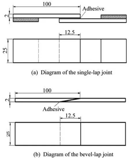
Fig.1 Diagram of the joint dimensions
The INSTRON 5982 electronic universal mate?rial test system with a load capacity of 100 kN is used as the test equipment.During the test,the two ends of the joint are clamped on the tensile testing ma?chine.The lower end is completely fixed,and the up?per end is applied with a longitudinal displacement load.The test process status is shown in Fig.2.
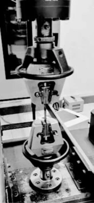
Fig.2 Diagram of the test process status
1.2 Test load-displacement curves
The test load-displacement curves of the singlelap and bevel-lap joints are shown in Fig.3,and the calculated shear strength for the single-lap and bevellap joints are shown in Fig.4.The results show that the bearing capacity of the bevel-lap joints is twice as much as that of the single-lap joints.

Fig.3 Load-displacement curves of the single-lap and bevel-lap joints
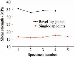
Fig.4 Calculated shear strength
1.3 Failure modes
There are four typical failure modes for fiber re?inforced composite bonded structures.
1.3.1 Cohesive failure
The adhesive is broken when the cohesive force of the adhesive layer is lower than that on theinterface of the adhesive and the adherend,and the separation occurs inside the adhesive layer.
1.3.2 Adhesion failure
The interface between the adhesive layer and the adherend is damaged,the adhesive force between the adhesive and the adherend is small,and the adhe?sive layer is completely separated from the adherend.
1.3.3 Adherence failure
The laminate is destroyed,the strength of the adherend is low,and the fibers are broken.
1.3.4 Mixed failure
Cohesive failure,adhesion failure,and adher?ence failure occur in combination.
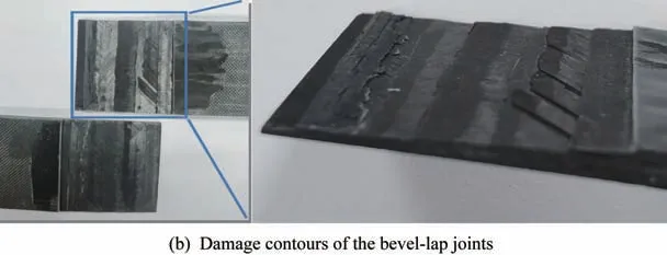
In this test,the failure mode of the single-lap joint is the adherence failure,and the 0° fibers on the surface of the laminate are subjected to tensile frac?tures,the damage contours of this failure are shown in Fig.5(a).The failure mode of the bevel-lap joint is the cohesive failure,and the damage contours of this failure are shown in Fig.5(b).
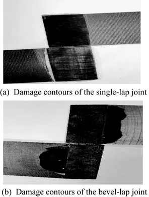
Fig.5 Damage contours of joint failures
2 Simulation and analysis
2.1 Finite element models
The three-dimensional(3D)finite element mod?els of single-lap and bevel-lap joints are established by using the ABAQUS simulation software.The boundary condition is that one end of the joint is com?pletely fixed and constrained by the reference point while the other end restrains all degrees of freedom except the tensile direction through the reference point.The uniform displacement load is applied in the direction of tension,and the actual tension load can be read by the reference point reaction.The bond?ing contact constraints are defined between the layers on the bonding area.Solid elements are used for mod?eling,and each ply of the composite laminate is rep?resented by a layer of C3D8R solid elements.The grid of the laminate finite element model is meshed layer by layer,and the meshes on the bonding area are refined.The nonlinear properties of the materials are considered in the models,as shown in Fig.6.
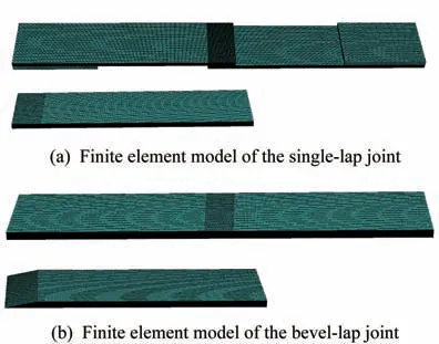
Fig.6 Finite element models of the single-lap and bevellap joints
2.2 Stress analysis
The single-lap joint element model is loaded ac?cording to the test load,and then the stress distribu?tions are carried out.The tensile stress of the singlelap joint is shown in Fig.7.The stress distributions in the bonding area along the lap length direction and the thickness direction at the end location(the start?ing position is shown in Fig.8)are shown in Fig.9.
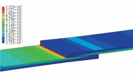
Fig.7 Distribution of tensile stress of the single-lap joint
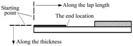
Fig.8 Diagram of the starting position of single-lap joint
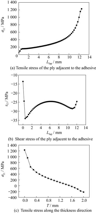
Fig.9 Stress distributions of the single-lap joint
According to the analysis of the curves in Fig.9,the maximum stress of the tensile stress of the ply ad?jacent to the adhesive occurs at the end connection position between two adherends,and reaches the ulti?mate tensile strength of M55J grade composites.The tensile stress along the thickness direction decreases sharply,owing to the large stress concentration coef?ficient on the surface of the laminate,especially for high modulus composites.Besides,the modulus dif?ference between the fiber and the resin matrix is greater,the anisotropy of the composites is more ob?vious,and the stress along the thickness direction of the laminate cannot be effectively transmitted.There?fore,under the action of the load,the tensile stress of the surface layer fiber exceeds its ultimate strength at the end of the stress concentration position,and the fiber fracture damage occurs,which is consistent with the phenomena of the test results.
The bevel-lap joint element model is loaded ac?cording to the test load,and the stress distribution is carried out.The tensile stress distributions of the bev?el-lap joint is shown in Fig.10.The stress distribu?tions in the bonding area along the bonding length di?rection and the thickness directions at three different locations(the starting position is shown in Fig.11)are shown in Fig.12.
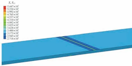
Fig.10 Distribution of the tensile stress of the bevel-lap joint
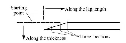
Fig.11 Diagram of the starting position of the bevel-lap joint
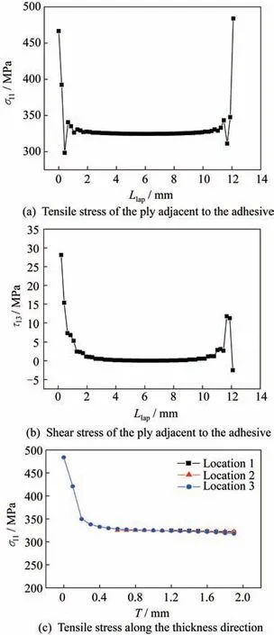
Fig.12 Stress distributions of bevel-lap joints
According to the analysis of the curves in Fig.12,one can obtain that the tensile stress of the ply adjacent to the adhesive of the bevel-lap joint is low in the adhesive bonding area and is basically in a horizontal state.The maximum stress occurs at the end of the adhesive bonding area,but the stress val?ue is also at a low level relative to the ultimate strength of the composite materials.Then,the ten?sile stress of each layer along the thickness direction is analyzed.
The results show that the stress value at the ex?treme end is slightly larger while the stress of each layer at other positions is basically horizontal.This indicates that the stress distribution of each layer of the laminate along the thickness direction is uniform.Compared with the single-lap joint,the bevel-lap joint optimizes the stress transfer path along the thickness direction,allows each layer of the laminate to share the load,avoids the stress concentration of the surface layer,and improves the bearing capacity.At this time,the shear stress reaches the shear strength value of the adhesive,and the adhesive will fail when the load increases.
The quasi-isotropic laminate is fabricated,which is used as the adherend of the bevel-lap joints with the same dimensions as the above bevel-lap joints.The tensile test is conducted according to the above test method.The test load-displacement curves are shown in Fig.13(a),and the damage contours are shown in Fig.13(b).
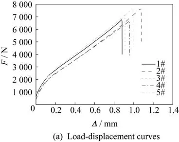
Fig.13 Experiment results of the bevel-lap joints with quasi-isotropic ply
From the damage contours,it can be seen that the mixed failure occurs,including adhesive layer damage and partial fiber tearing failure with 90° and 45° layers,and the failure surface has obvious con?cave-convex feeling.
According to the test results,we can conclude that the bearing capacity is still improved compared with the single-lap joint,but is lower than that of the original bevel-lap joint.The reason is that since many fiber layers of the bevel-lap joint are involved in the stress transfer,when the tensile stress of some layers exceeds its ultimate strength,the local fiber tearing failure will occur,which will lead to the reduction in the load area and the decrease in the bearing capacity.
Continue Fig.13 Experiment results of the bevel-lap joints with quasi-isotropic ply
3 Conclusions
In this paper,a new idea for the study of the ad?hesive bonding properties of composite materials is provided.Through the tensile test and finite element numerical simulation,the following conclusions are drawn for the single-lap and bevel-lap joints of high modulus composites.
1)In the tensile process of single-lap joints of composite laminates,owing to the large modulus dif?ference between the fiber and the resin in the lami?nate,the stress concentration of the ply adjacent to the adhesive layer is serious,and the stress cannot be effectively transmitted along the thickness direction of the laminate.When the tensile stress exceeds its ultimate strength,the ply adjacent to the adhesive will fail.
2)Compared with the single-lap joint,the bev?el-lap joint changes the stress transfer path in the loading process,which allows each layer of the lami?nate to share the load and avoids the stress concentra?tion on the surface layer,and thus the stress of each layer is uniform and the bearing capacity is improved.However,when the tensile stress of some layers ex?ceeds their tensile strength,local fiber failure will al?so occur.

- 上海航天的其它文章
- 序言
- 企業簡介
- Microstructure and Property Analysis of AerMet100 Steel Manufactured by In-situ Rolling Mixed Wire Arc Additive Manufacturing
- Linear Shaped Charge Cutting Property and Charge Cutting Mechanism of Mg-Gd-Y-Zn Alloy
- Effect of Isothermal Forging on the Microstructure and Mechanical Properties of Mg-8Gd-3Y-0.5Zr Alloy
- Fabrication and Investigation on Double-Hollow Shell CoFe Oxide@TiO2 Nanocube with Superior Electromagnetic Properties