Electrical-Mechanical Coupling Behaviors and Thermal-Resistance Effects of 3D Braided Composites
2021-11-02 03:12:38BAILeiXUEYousong薛有松SUNBaozhong孫寶忠GUBohong顧伯洪HUMeiqi胡美琪
BAI Lei(白 雷), XUE Yousong(薛有松), SUN Baozhong(孫寶忠), GU Bohong(顧伯洪), HU Meiqi(胡美琪)
College of Textiles, Donghua University, Shanghai 201620, China
Abstract: Electrical-mechanical coupling behaviors and thermal-resistance effects of 3D braided composites under external loads are important for structural health monitoring(SHM). Electrical conductivity and electrical-mechanical coupling behaviors of 3D braided carbon fiber/epoxy composites under uniaxial tension were reported. It was found that the transverse resistance decreased and the axial resistance increased with the increasing braiding angle. The fractional change in resistance increased linearly as the strain was below 1.0%, and the nonlinearity appeared when the strain exceeded 1.0%. The negative temperature coefficient(NTC) effect was observed before the glass transition temperature Tg of epoxy resin, while there was a positive temperature coefficient(PTC) effect after Tg.
Key words: 3D braided composite; braided angle; electrical property; thermal analysis
Introduction
3D braided composites have been widely used in aerospace, vessels, and other industrial fields[1-3]. Considering the potential damages caused by external loads, electrical-based structural health monitoring(SHM) technique for damage detection has attracted great attention in the past few decades[4-8]. The resistance changes under external loads are investigated to reveal the composite damages and achieve the SHM purpose[9-11].
Carbon fiber tows have good conductivity, while epoxy resin can be regarded as an insulator. The electrical conductivity of carbon fiber reinforced composites highly depends on the conductive network formed by carbon fiber tows[12-13]. The conductive network undergoes disruption and reorganization under external loads, resulting in resistance changes at the macroscopic level[4, 14].
In previous studies, the resistance change of laminated composites was reported under both static and cyclic tensile loading[11, 15], compression[16-17], flexure[6, 18], impact[19-20], and thermal loads[21-23]. Chenetal.[15]studied the stress dependency of conductivity under monotonic and cyclic loading, which proved that the damage occurring inside material could be monitored in real time by measuring the change in resistance during loading and unloading. Zhu and Chung[18]provided an analytical model of the piezoresistive phenomenon of carbon fiber-polymer matrix composites under flexure, which attributed the surface resistance change to the degree of current penetration. Swaitetal.[20]investigated location, spacing and orientation of the contacts in laminate to optimize the SHM system for improved sensitivity and accuracy. Chung[21]provided information on structural transitions, residual stress, composite interfaces, composite fabrication process, and thermal damage with the resistance measurement method. However, few papers were published to reveal the resistance changes in 3D textile structural composites, especially for 3D braided composites.
Here we investigated axial resistivity and transverse resistivity of 3D braided composites with the four-probe method and the two-probe method, respectively. The electrical-mechanical coupling behaviors were studied to explore the damages under tensile loading. The thermal-resistance effects were also investigated during heating and cooling in the temperature range from 35 ℃ to 150 ℃.
1 Experiments
1.1 Sample preparation
The 3D carbon fiber(T700-12k, Zhongfu Shenying Carbon Fiber Co., Ltd., Lianyungang, China) braided preforms were fabricated with 1 × 1 four-step braiding technique. The epoxy resin(JC-02A, Changshu Jiafa Co., Ltd., Changshu, China) was injected into the preforms with vacuum-assisted resin transfer molding(VARTM) technique. Mechanical and electrical parameters of carbon fiber and epoxy resin were listed in Table 1. The braiding angleαused in this paper refers to the surface braiding angle, which is described as
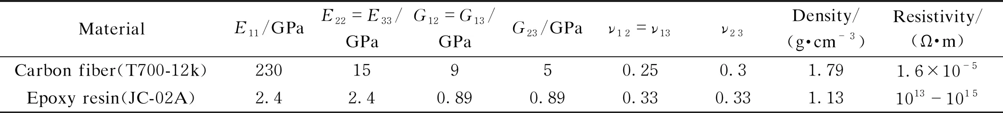
Table 1 Mechanical and electrical parameters of carbon fiber and epoxy resin
(1)
whereWis the width of the specimen,nis the number of main yarns along the width, andhis the knot height.
Figure 1 presents the 3D braided composites with the braiding angles of 18°, 30°, and 42°. Table 2 lists the fiber volume fractions of samples with different braiding angles.
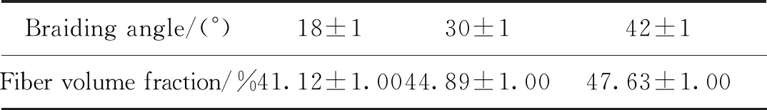
Table 2 Fiber volume fraction of composites with different braiding angles
1.2 Tests
The samples with a size of 7 mm×50 mm×70 mm were used for transverse resistivity measurement. The transverse resistivity was measured with the two-probe method. As shown in Fig.2, two copper electrodes were configured at the sample surface in the transverse direction for both current introduction and voltage measurement.
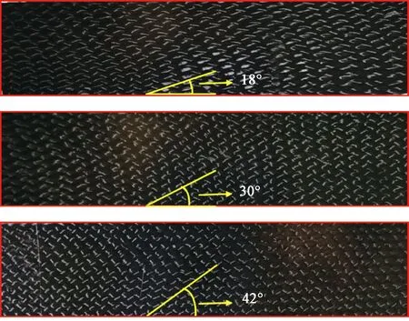
Fig. 1 3D braided composites with different braiding angles
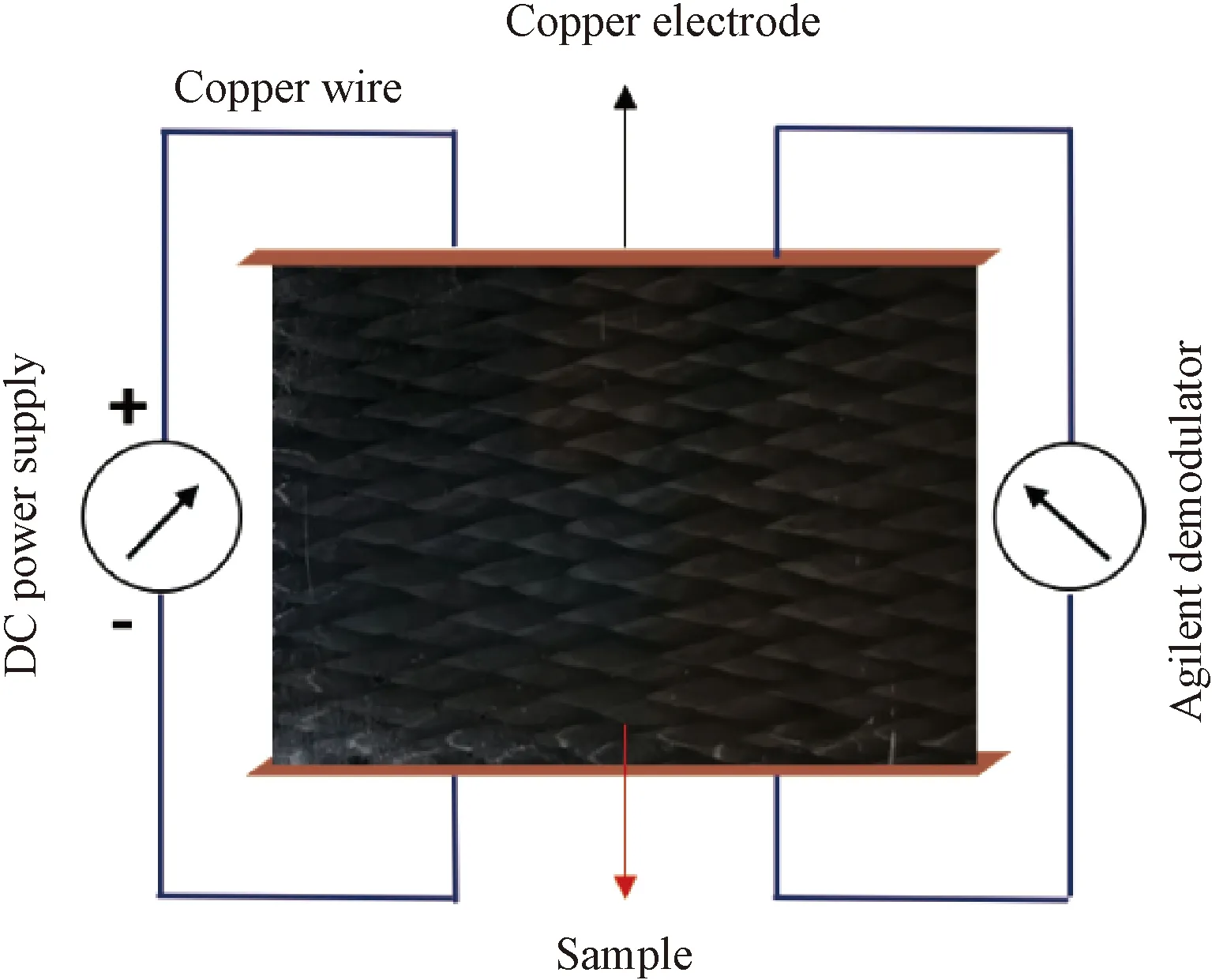
Fig.2 Sketch of transverse resistivity measurement
The axial resistivity of composites was tested with the four-probe method. Samples with a size of 200 mm × 150 mm × 5 mm were prepared. As shown in Fig.3, two copper electrodes were configured at the ends of the sample, while another two copper electrodes were placed at the ends of the test region. The two outer probes were used to introduce current, and the two inner probes were used for voltage measurement.
Uniaxial tensile tests were conducted with the material test system(MTS) at a loading speed of 2 mm/min as shown in Fig. 4. During the loading process, the electric current of 100 mA was introduced into the sample. The axial resistance changes were measured with the four-probe method. Two strain gauges were pasted on the axial surface of the sample and their average value was taken as the strain. An Agilent demodulator was used to demodulate the voltage and strain in real time.
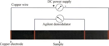
Fig. 3 Sketch of axial resistivity measurement
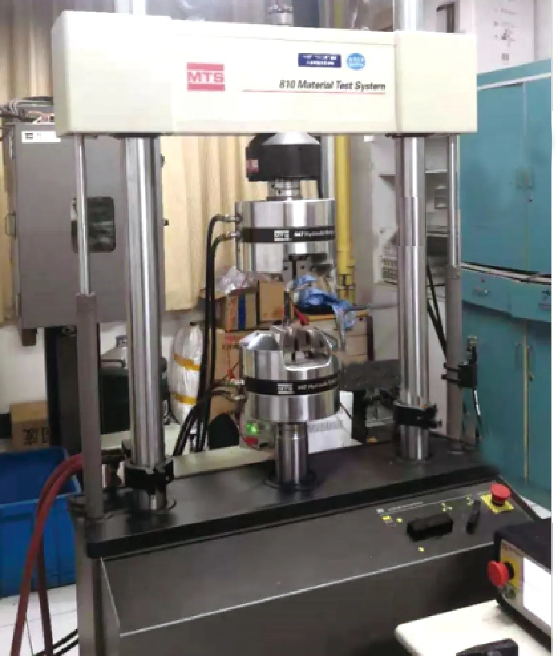
Fig. 4 Electrical-mechanical coupling test system
The axial resistivity was also measured during a thermal cycle from 35 ℃ to 150 ℃. The whole testing process was conducted in an oven and a thermocouple was attached to the sample surface for temperature signal collection. An Agilent demodulator was used to decouple the temperature signal and record voltage simultaneously.
2 Results and Discussion
2.1 Electrical properties
Figure 5(a) shows the voltage-current relationships of the 3D braided composites with current introduced in the transverse direction. The voltage increases linearly with the increase of current, showing typical ohmic behavior under a steady direct current(DC) electric field within the current range from 0 to 1.0 A. The transverse electrical resistivity decreases with the increasing braiding angle as shown in Fig. 5(b).
As shown in Fig.6(a), the axial voltage-current curves of 3D braided composites exhibit similar regularity to that of the transverse ones,i.e., the voltage increases linearly within the current range from 0 to 1.0 A. Figure 6(b) shows the axial resistivity of samples with the braiding angles of 18°, 30°, and 42°. The axial electrical resistivity increases with the increasing braiding angle.
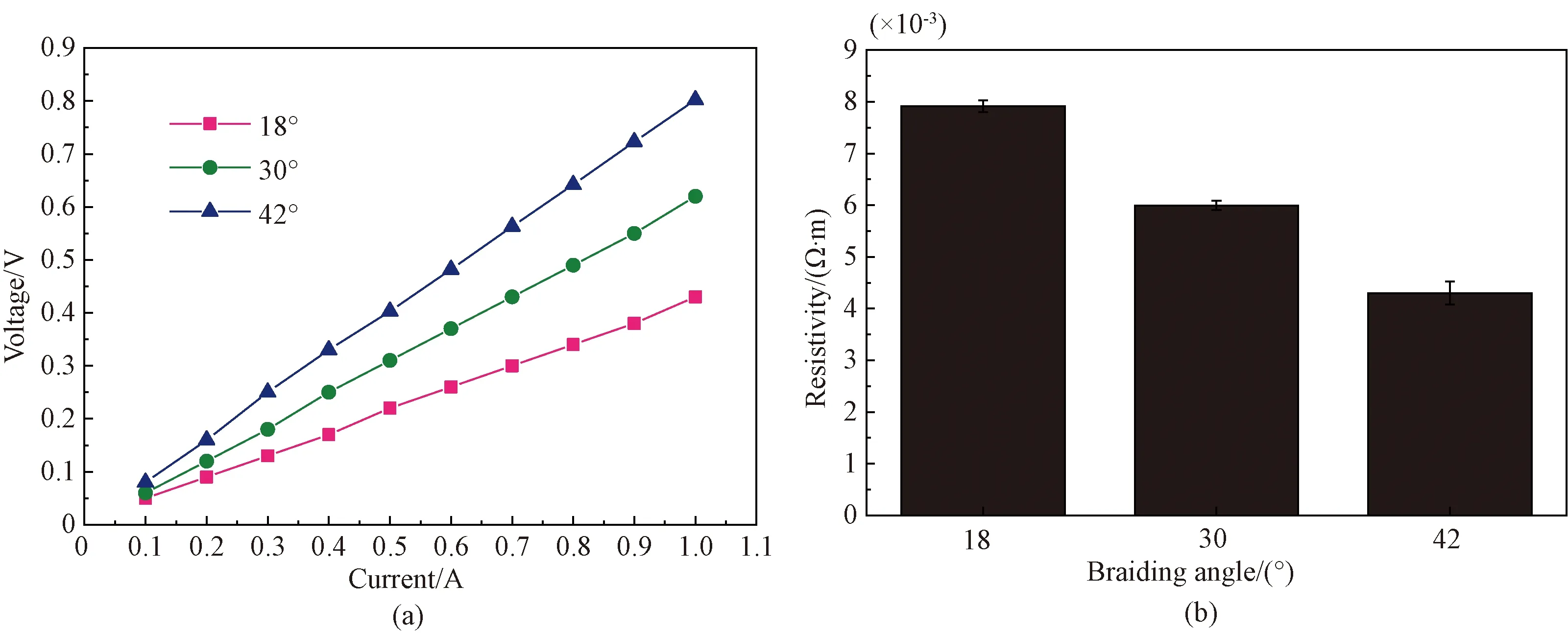
Fig. 5 Transverse properties: (a) transverse voltage-current curve; (b) transverse resistivity
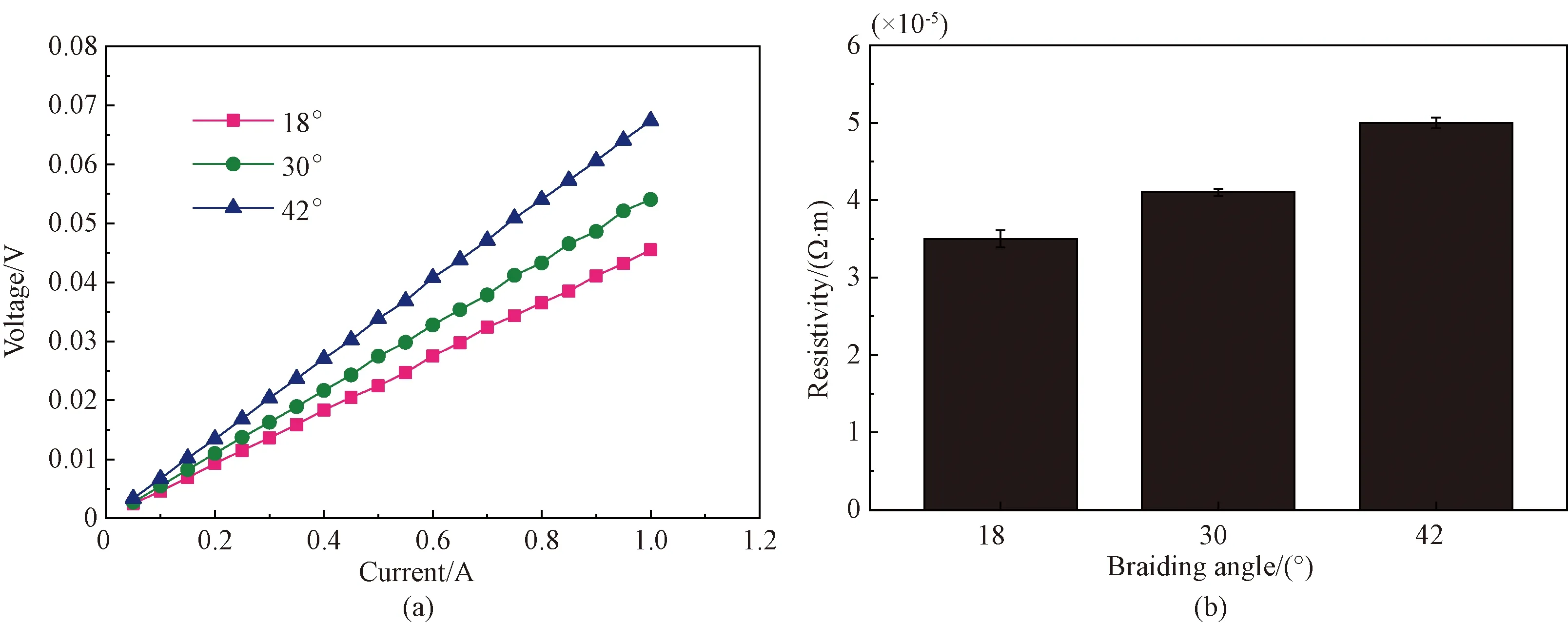
Fig. 6 Axial conductivity: (a) axial voltage-current curve; (b) axial resistivity
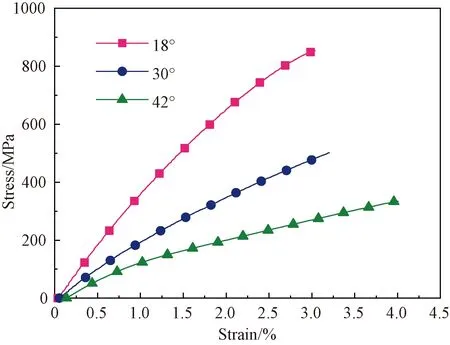
Fig. 7 Stress-strain curve
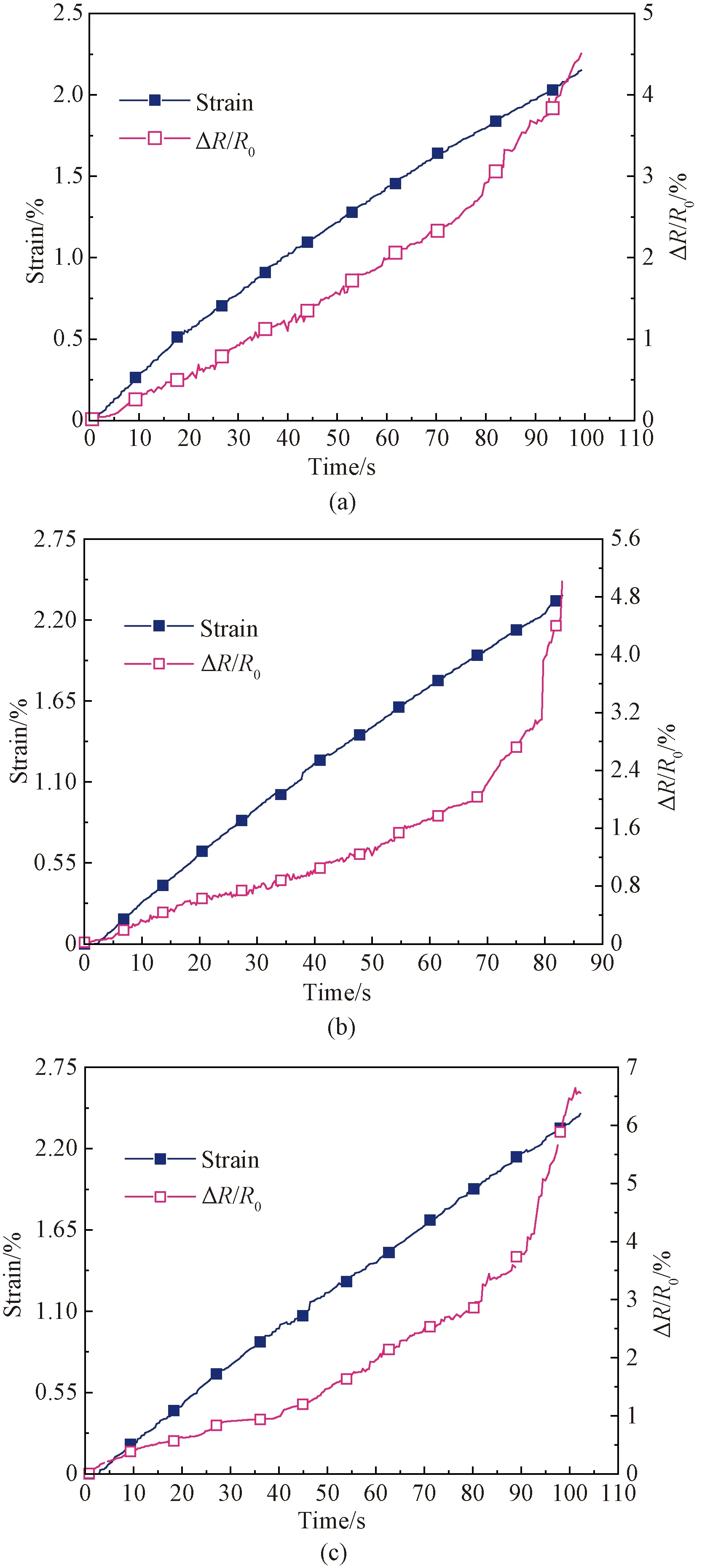
Fig. 8 Electrical response of samples with different braiding angles under quasi-static tensile loading: (a) 18°; (b) 30°; (c) 42°
In 3D braided composites, the conductive network is formed by continuous carbon fiber tows and the contacts between the fibers. The axial electrical conductivity depends on the conductive path formed by continuous carbon fiber tows in the braiding direction, while the transverse conductivity depends on the contact between the carbon fiber tows. The conductive network of 3D braided composites is related to the braiding angle. The larger the braiding angle, the more severely the fibers buckled. The buckled fibers lead to an increase in contact. In this case, the transverse resistivity decreases with the increasing braiding angle. The buckled fibers also increase the length of the conductive path, increasing the axial resistivity.
2.2 Electrical-mechanical behaviors under tensile loading
2.2.1Tensilebehaviors
Figure 7 shows the stress-strain curves of 3D braided composites with the braiding angles of 18°, 30°, and 42°. The failure stresses are 853.8, 501.8, and 333.5 MPa and the fracture strains are 3.0%, 3.2%, and 4.0%, respectively. For the sample with a braiding angle of 18°, the tensile behavior depends on the carbon fiber tows, whose excellent mechanical properties result in high modulus and strength. For the samples with braiding angles of 30° and 42°, the carbon fiber tows buckle and the influence of epoxy resin on the mechanical behaviors becomes apparent. Ductile failure occurs in the tensile tests, resulting in an increase of fracture strain[1].
2.2.2Electrical-mechanicalcouplingbehaviors
The electrical responses depend on the deformation and damages of composites during tensile loading. The relationship of fractional change in resistance and strain is given by[24]
(3)
whereR0is the initial resistance, ΔRis the resitance change,ρ0is the initial resistivity, Δρis the resistivity change,εis the strain, andvis the Poisson’s ratio.
Figure 8 shows the relationships of fractional changes in resistance and strains of samples with the braiding angles of 18°, 30°, and 42° under quasi-static tensile loading. The fractional changes in resistance increase linearly until strains reach about 1.0%. In this case, the resistance changes depend on the dimensional changes contributed by the Poisson effect. The resistance is directly proportional to the length and inversely to the cross-sectional area. During the loading process, the displacement is generated by the stretch and the width of the composites decreases, resulting in a linearly increase of change in resistance.
With the increase of strains from 1.0% to 1.5%, the nonlinearity of the resistance change curves was observed. The buckled carbon fibers in the braiding structure are straightened gradually. The extrusion between fibers and epoxy resin leads to the cracks inside the composites, which results in the destruction and reconstruction of the conductive network. As a result, the fractional changes in resistance begin to nonlinearly increase.
As the strains exceed 1.5%, the fractional changes in resistance increase nonlinearly to the maximum until samples breakdown. The fracture of carbon fibers causes breaks in the conductive paths, and the unbroken carbon fibers reconstruct the conductive network. The reduction in the content of continuous carbon fiber tows leads to resistance increases.
The gage factor(GF)Kis defined as the fractional change in resistance per unit strain[24],
(2)
Figure 9 reports the GF of samples obtained from Fig. 8, corresponding to the strain range from 0 to 1%. The sample with the braiding angle of 18° has the largest GF value.
2.3 Thermal-resistance effects
The resistance-temperature curve of carbon fiber tows was measured during the heating process from 20 ℃ to 150 ℃. As shown in Fig. 10, the resistance decreases linearly with the increasing temperature, exhibiting the semiconductor feature. The resistance decreases by 3.2% from 20 ℃ to 110 ℃ and 5.2% during the entire heating process.
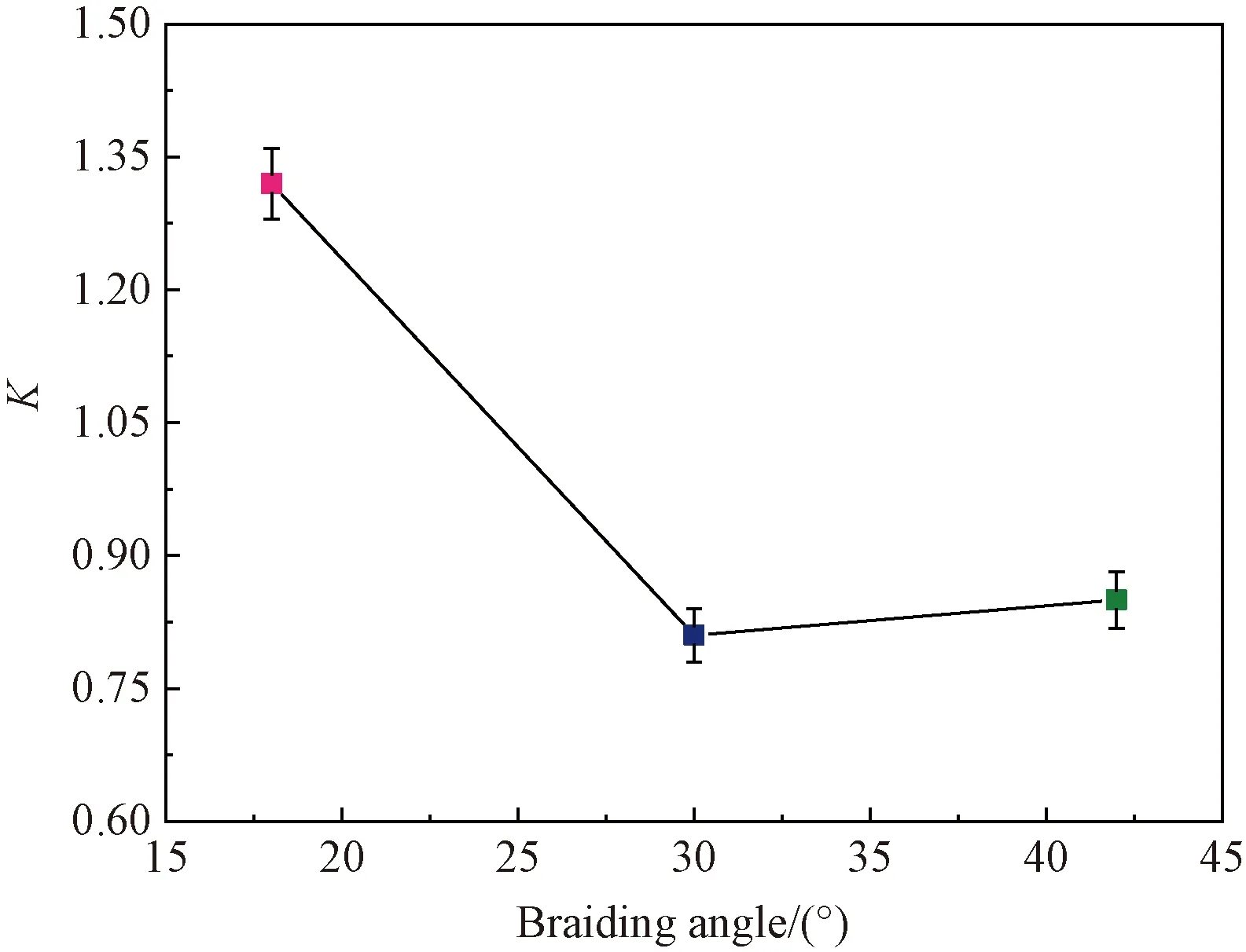
Fig. 9 GF of composites with different braiding angles
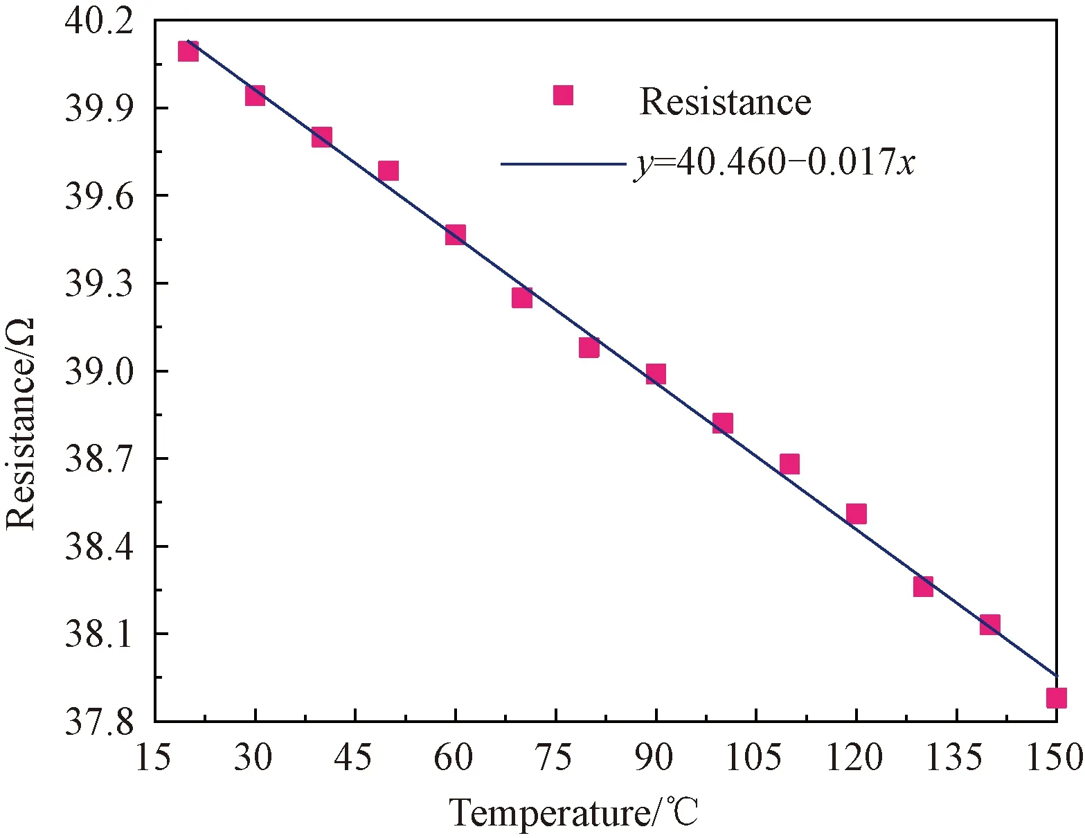
Fig. 10 Resistance-temperature curve of carbon fiber tows
The resistivity-temperature curves of 3D braided composites with different braiding angles are exhibited in Fig. 11. The resistivity-temperature curves show an opposite trend before and after 110 ℃. The resistivity of samples with braiding angles of 18°, 30°, and 42° decreases by 3.9%, 1.5%, and 2.3% as the temperature increases from 35 ℃ to 110 ℃, and increases by 8.0%, 4.9%, and 4.5% when the temperature rises from 110 ℃ to 150 ℃. The thermal-resistance effects of carbon fiber tows(discussed in the first paragraph of section 2.3) and the thermal expansion of epoxy resin contribute to the resistance changes.
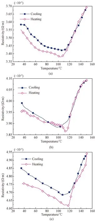
Fig. 11 Resistivity-temperature curve of 3D braided composites with different braiding angles: (a) 18°; (b) 30°; (c) 42°
The thermal expansion of epoxy resin has little effect on the conductive network before the temperature reaches 110 ℃(Tgof epoxy resin)[25]. The electrical conductivity of 3D braided composites mainly depends on the thermal-resistance effects of carbon fiber tows. The resistivity reduction in the carbon fiber tows causes the negative temperature coefficient(NTC) effects in the temperature range from 35 ℃ to 110 ℃. The thermal expansion of epoxy resin in the elastic region changes the conductive network as the temperature exceeds 110 ℃[26]. The carbon fiber tows are separated by the volume expansion of epoxy resin, leading to the reduction of contact. Destruction and reorganization in the conductive network increase the resistivity in the temperature range from 110 ℃ to 150 ℃, exhibiting the positive temperature coefficient(PTC) effects.
The resistivity-temperature curves of 3D braided composites are also reported during the cooling process as shown in Fig.11. The resistivity decreases with temperature from 150 ℃ to 110 ℃ and increases with temperature from 110 ℃ to 35 ℃. The difference in coefficient of thermal expansion between carbon fiber tows and epoxy resin causes the stretches in composites under thermal loads[26], which leads to irreversible changes in the conductive network. During the cooling process, the broken conductive network cannot be recovered and exhibits the resistivity recovery hysteresis.
3 Conclusions
The electrical conductivity, electrical-mechanical coupling behaviors, and thermal-resistance effects of 3D braided composites have been investigated. It is found that the axial resistivity increases and the transverse resistivity decreases with the increasing braiding angle. The fractional change in resistance increases linearly until the strain reaches about 1.0%, and exhibits nonlinearity when the strain exceeds 1.0% under quasi-static tensile loading. The sample with the braiding angle of 18° has greater GF than the samples with a larger braiding angle. The resistivity decreases and increases with the temperature increase before and after 110 ℃ respectively owing to the thermal expansion behaviors of epoxy resin and the reduction in resistivity of carbon fiber tows.
 Journal of Donghua University(English Edition)2021年5期
- Journal of Donghua University(English Edition)的其它文章
- Ecological Dyeing of Polyamide 6, 6(PA66) Fabrics with Monascus Pigments in Decamethylcyclopentasiloxane(D5) Solvent
- Effects of Microstructure on Quasi-Static Transverse Loading Behavior of 3D Circular Braided Composite Tubes
- Efficient Probabilistic Load Flow Calculation Considering Vine Copula-Based Dependence Structure of Renewable Energy Generation
- Turing Instability of Diffusive Predator-Prey System with Gompertz Growth
- Blockchain-Based Log Verification System for Cloud Forensics
- Order Allocation in Industrial Internet Platform for Textile and Clothing