一種使用幀間差值的圖像傳感器片上視頻壓縮算法?
2021-06-16 10:35:44蔣永唐徐江濤陳全民衡佳偉天津大學微電子學院天津30007天津市成像與感知微電子技術重點實驗室天津30007
傳感技術學報 2021年3期
蔣永唐徐江濤?陳全民衡佳偉(.天津大學微電子學院,天津30007;.天津市成像與感知微電子技術重點實驗室,天津30007)
With the development of fifth-generation mobile communication and multimedia technology,real-time video transmission with higher resolution is widely distributed in various fields,which consumes larger bandwidth resources.The application of image sensors in the field of portable wireless camera and lossless biomedical video applications have posed new design challenges[1].For example,in the conventional image sensor about 222-Mbit of data within one second is generated when stream an uncompressed 1280×7208-bit video at 30 frames/s.
Various standard-based off-chip video compression algorithms have been proposed,which are widely used for efficient video compression,such as H.264/AVC[2-4], H. 265/HEVC[5-6], etc. The image compression system with an optimisation of compression ratio is reported in Ref.[7].This system automatically sets an optimal compression ratio for particular image content while maintaining a tolerable image quality.However,these algorithms require additional chips and cannot meet the requirement for the one-chip camera system for portable consumer products.Additional video compression hardware increases the cost and size of digital video camera systems[8].On-chip video compression leads to a cost-effective implementation since the compressed video data is output directly from the sensor.Some complementary metal oxide semiconductor(CMOS)image sensors[9]with image compression functions have been reported such as the computational image sensor with conditional replenishment and the CMOS image sensor with analog two-dimensional discrete cosine transform(2-D DCT)processor[10-11].
In Ref.[12]a compression algorithm using a blockbased differential coding scheme is proposed.The algorithm utilizes a reduced number of bits to indicate the differences between pixels in the cost of image quality.An imaging circuit has been proposed in Ref.[13],containing event-based change detection[14]and pulse-width-modulation(PWM)[15].The sensor asynchronously encodes in inter-event intervals after each detected event change. High-efficiency video compression is achieved by suppressing time redundancy and discarding redundant pixels.In Ref.[16],the single chip image sensor with an on-chip image compression processor is reported.The compression algorithm is based on the hybrid predictive boundary adaptation processing and quadrant tree decomposition(QTD)encoder[17-18].In Ref.[19],a super-pixel based on-chip image compression scheme is proposed.The image compression is realized by reading only one sample for each super-pixel.Although these algorithms have achieved good compression effects,the compressed images or videos are lossy.
To meet the requirement of lossless compression and portable products,this paper presents a lossless video compression algorithm for one-chip CMOS video cameras.The proposed scheme is based on block-based lossless compression(BLC)scheme and differential pulse code modulation(DPCM).The proposed compression algorithm is based on two steps:firstly,calculate the differences between the pixel values in the current frame and the pixel values stored in the previous frame.In the second step,a modified coding scheme is employed for compressing differences.The BLC coding scheme is based on the modified delta size unit-variable length coding(DSU-VLC)[20-21].And it allows to represent multi codewords referred to a given acquisition with the same prefix.
1 Block-based lossless compression
Traditional image sensor compression algorithms usually sacrifice the accuracy of image data to ensure image compression efficiency[22]. The compression algorithm proposed in this paper achieves the lossless compression of video in the sensor by taking advantage of the of pixels at the same position between adjacent video frames.The sensor encodes pixels value in units of pixel blocks,as shown in Fig.1.Firstly,the pixel array of the sensor is divided into several 8×8 blocks,and all pixel blocks of the sensor pixel array are read out by column-level readout circuit.Then the differences between the voltage value of the current photodiode and the last captured voltage value for video coding are calculated and converted.The converted differences are stored in memory in digital form.By encoding the differences between pixels to represent the original pixel values that the data needed to transmit are greatly reduced.Therefore,the demands for the external storage of video data is significantly reduced.

Fig.1 Sensor and pixel block structure
According to the characteristics of pixel array,this paper presents a block-based lossless coding scheme.BLC is a kind of lossless entropy coding scheme proposed in the paper,which solves the problem of variable length residual coding in image sensor.Compared with the DSU-VLC algorithm,the BLC encodes more residuals at a time,which greatly improves the encoding speed.The significant advantage of the BLC code scheme with respect to other lossless solutions,such as Huffman codes[23],is that encoding is accomplished without the requirement of a coding table by using prefix-free codes,resulting in a considerable reduction of the needed memory space.The output structure of DSUVLC and BLC scheme are shown in the Fig.2.The BLC has two modes:difference mode and pixel mode.Both modes include a prefix and a suffix.The prefix indicates the bit-length of the difference that follows in the suffix.All differences in the block are coded within in the suffix,as shown in Fig.2(b).Before encoding,the digital logic module search for the difference with the largest absolute value in the block and output the number of bits required to represent the difference.The BLC generates a prefix based on the number of output bits.If the number of bits required to express the difference exceeds 7 bits,the pixel mode is used to encode the data output from the sensor,otherwise use difference mode.The difference mode is preferred in the design of encoding circuit.The differences within the memory are first used for encoding,after the pixel values and the differences stored in the memory.Then,each difference is contained within as many bits as the calculated bitlength of the difference which has the largest absolute value,leading 0s inserted or sign extension used if the differences are small.If the bit-length of the difference exceeds 7 bits,the original pixel values are read out for encoding and the prefix is defined as‘000000001’.

Fig.2 Coded pixel data output structure
The prefix in the BLC scheme is encoded with a modified unary code.The code table of the unary code is shown in Table 1.

Table 1 Prefix code table
A numerical example is presented in Fig.3.In the Fig.3,it is considered the compression of the differences{-3,+2,+5,-1,+1}composed by 5 elements acquired with 8 bits of resolution.The first step is mapping each difference in a two’s complement form,where the corresponding complement representations are:1111_1101,0000_0010,0000_0101,1111_1111,0000_0001.The maximum number of bits required to code these 5 differences is 4 bits.The raw differences are represented with a codeword 40 bits.However,the length is reduced to 25 bits after the BLC is performed.
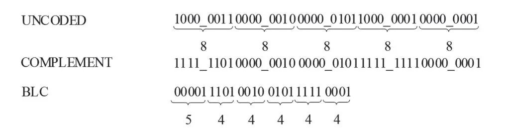
Fig.3 Numerical example of BLC coding process
The compression process of the video compression algorithm proposed in this paper is shown in Fig.4.

Fig.4 Block diagram of video frame compression process
①Collect the photo generated charges and store them in pixels.
②Read out the analog signal of the previous frame and the current frame in the pixel and calculate the difference between the two signals.
③Convert the difference value and the original value into digital form and store them in memory.
④Find the maximum number of bits required for encoding the differences in a block and determine which encoding mode to use.When the required maximum number of bits(Max_bits_required)is greater than 7 bits,the original pixel values are read out for encoding,otherwise the differences are used.
⑤Execute BLC processor and output bit stream.
2 Block-level processing and Performance optimization
2.1 Block-based compression algorithm
There is a lot of redundant information in the video data.These redundancies could be eliminated through the compression algorithms as the memory consumption and bandwidth requirements are reduced.In this paper,7 sample videos are tested.And each sample video has a duration of 10 seconds as the video resolution is 1280×720@ 60fps.The pixels differencesD(i,j)between two adjacent frames are calculated and then the probabilities of the differencesP(x)in the sample videos are counted.Fig.5 shows theP(x)for different differences and different sample videos.As shown in Fig.5,the number of 0 occupies 30%~50%in all the frame differences,which means that 30%~50%of the pixel values are equal between the two adjacent frames.The distribution of the differences between two adjacent frames of pixel values in the video is like the Gaussian distribution.Therefore,the distribution probability of the differences within the sample video could be approximately expressed as:
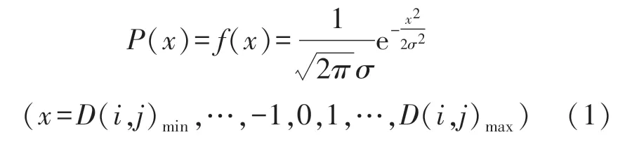
whereσis the standard deviation of the Gaussian distribution function.Typically,D(i,j)is a 9-bits data with a sign bit,the minimumD(i,j)minand maximumD(i,j)maxare-255 and 255 respectively.
In the process of video shooting,the same scene may be sampled multiple times due to the high frame rate.And there is almost no change between adjacent frames.Therefore,the sampled value of pixels at the same position changes slightly.In addition,only a few pixels change significantly in some static scenes and the remaining pixels do not change.According to the simulation results in Fig.5,it could be clearly found that the differences between pixels are mainly between-5 and 5.After coding by BLC,the values between-5 and 5 are represented by only 4 bits or less.In other words,one 8-bit pixel data is represented by 4 bits.Therefore,the temporal redundancies in the video could be removed by using the characteristics between consecutive frames.That is why the video data are effectively compressed by encoding the differences between consecutive frames.The differences between the current frame and the last frame are calculated in the sensor.

Fig.5 Probability distribution of the differences between two adjacent frames of sample videos
In our compression algorithm,the pixel array is decomposed into blocks.The values within the memory are encoded in the BLC circuit block by block.In addition,the obtained differences are stored in the memory with 8-bit full precision,accumulation error is completely avoided.

Fig.6 Strategy to find the maximum absolute value of the differences
The differential encoding scheme explained above is only the first step of the pixel compression process,further BLC entropy coding process is needed.Firstly,the maximum number of bits needed to represent a difference in the block is calculated in BLC.The prefix and suffix in the BLC algorithm are determined by the maximum number of bits.Fig.5 describes the strategy of addressing the maximum number of bits needed to represent the difference.At first the block is decomposed into four sub-blocks.Each sub-block is continued to be decomposed until the sub-block size is 2.As shown in Fig.6,the absolute values of the differences in each sub-block are bitwise OR.L1 is the result of bitwise OR of four differences‖(i,j)‖.L2 is the result of four L1 bitwise OR.According to the value of L2,the encoding mode and the number of bits required for encoding are determined.If the L2 value corresponds to‘00000000’,then the encoding uses “Diff” mode and the number of encoding bits is 1.
These differences are then encoded by BLC,using a reduced number of bits(as shown in Fig.3)as their accuracy is lossless.To better understand how the proposed compression algorithm works,it is assumed for simplicity that the camera is shooting a still scene in an ideal state.Therefore,the values of each frame in the video are the same.The differences from all pixels are‘00000000’.According to the strategy in Figure 6,the value of L2 is‘00000000’.At the same time,we can know that the coding mode is “diff” ,and the number of coding bits is 1.In other words,the difference value is input into the BLC module for encoding,and each difference value is represented by one bit.So that the eightbit original pixel value is represent by one-bit‘0’,which significantly reduces the number of output bits.Since the differences are obtained by subtracting the pixel values of the current frame and the pixel values of the previous frame,the original pixel values are obtained from the differences and the pixel values of the previous frame in the reverse order.
2.2 Performance optimization
Since the depth of the sample video is 8 bits,the algorithm stipulates that the number of bits encoding the differences must be less than 8 bits.This not only avoid errors in pixel mode and difference mode during decoding,but also reduce the number of bits required.The minimum 8-bit difference between pixels representing video frames is the number of symbols 64 or-64.Therefore,the algorithm must use pixel mode when the absolute value of the difference exceeds 63.The remaining range that the suffix expressed is-63 to 63 in the difference or pixel mode.Besides,the critical threshold for switching from the difference mode to the pixel mode will also affect the video compression effect.To derive some design guidelines with respect to the optimum threshold,exhaustive simulations on various block sizes is conducted,as illustrated in Fig.7.The figure illustrates the BPP as function of the absolute value of differences.The absolute values of the tested threshold are 0,1,3,7,15,31,63,which correspond to the maximum difference that are represented by 1 bit,2 bit,3 bit,4 bit,5 bit,6 bit,and 7 bit.It clearly illustrated that the minimum BPP is obtained for the absolute value of threshold 63.At the same time,the Fig.7 proves that the video compression works best when the block size is 4×4.
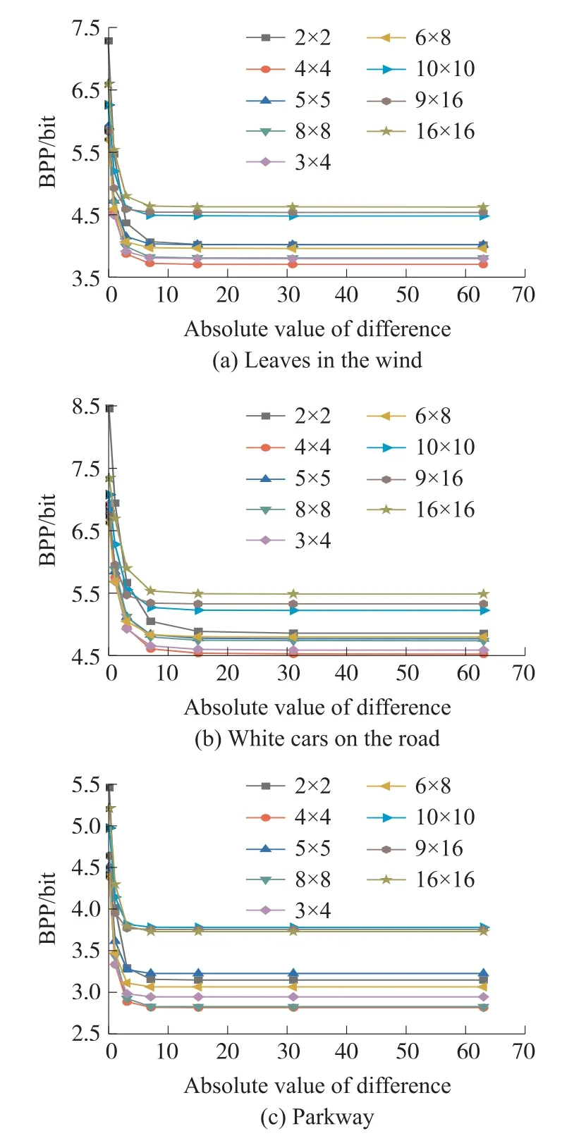
Fig.7 In different sample videos,the relationship between the compressed BPP of sample videos with different block sizes and the threshold changes
As mentioned in the previous section,the differences in each block are quantified and encoded by BLC using the largest number of bits in the current block.The size of different blocks lead to changes in the number of bits,requiring to represent the values of the block.It is necessary to select the appropriate block size to minimize the number of bits required to represent pixel values in a block.Fig.8 shows the differences stored in the memory during the sensor encoding process.It shows that the block size has a great influence on the number of encoded bits.In this subsection,the block size is set through formula derivation and algorithm simulation to improve the video compression effect.

Fig.88×8-pixel differences block
Assume thejthdifference value in theithblock is(i,j).Piindicates the number of bits for the prefix.Therefore,the number of bits required for block coding is expressed as follows:

WhereK1andK2represent the number of rows and columns of the block,respectively.Therefore,the bit per pixel(BPP)is expressed as follows:

Since the size ofPiis determined by the video content,the best BPP value is calculated by adjusting the block size in different sample videos.A system-level simulation of the sample videos is performed.The specification of the sample video is 720P(1280×720)@60 fps.To completely divide a frame of image into blocks,nine different block sizes are set.The number of bits after sample video encoding is calculated according to(1).Therefore,code_bits output after the sample video encoding is expressed as follows:

Wherenis the number of blocks in a frame and expressed as follows:
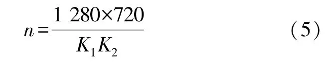
Table 2 shows the simulation results of the number of bits and the compression ratio expressed in BPP for different sample videos using different block sizes.The table shows that the amount of compressed data is the smallest in these sample videos when the block size set as 4×4.
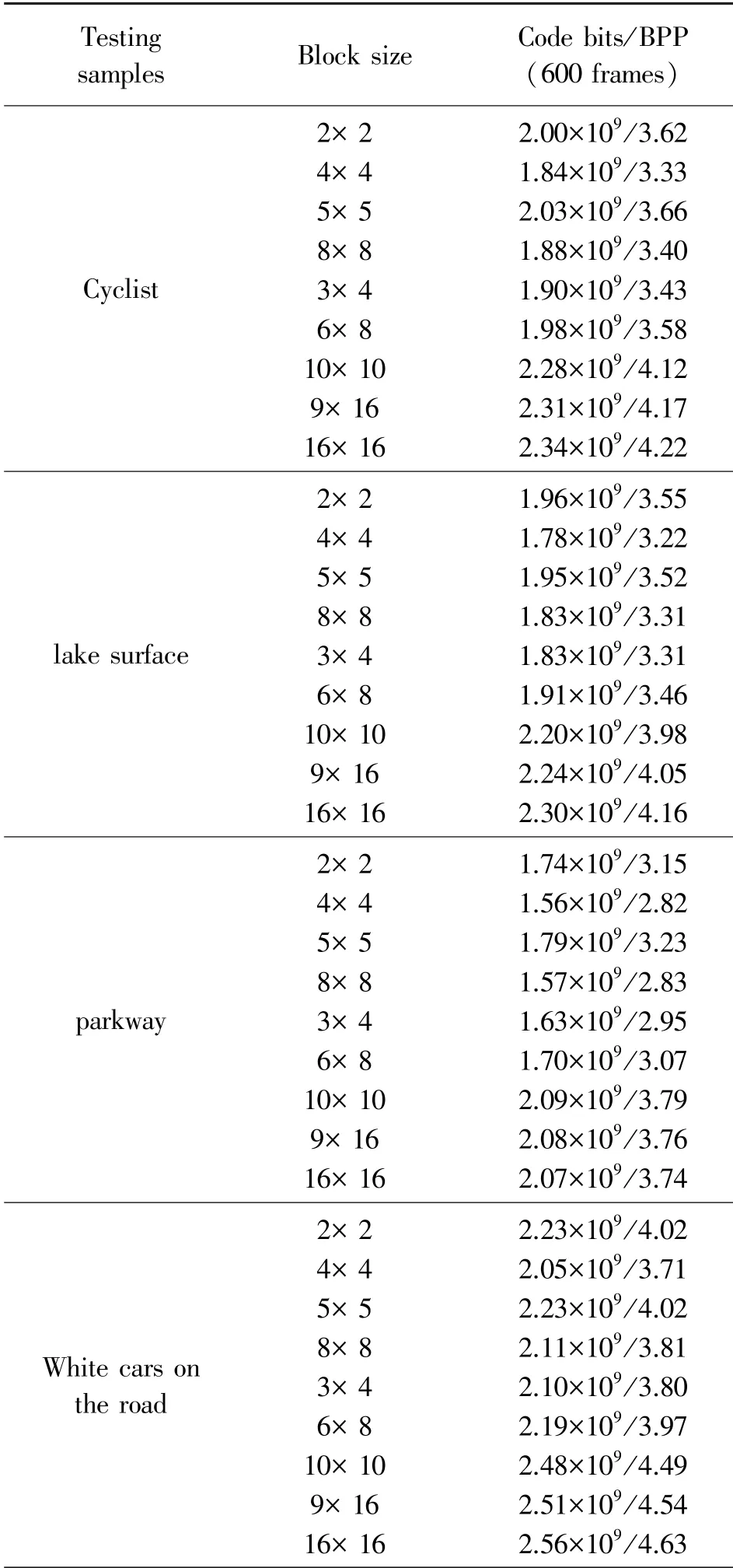
Table 2 Simulation results for different sample videos with different block sizes when threshold=63
2.3 Simulation analysis
It is worth noting that the pixel sample different values each frame in the real world,even though the scene being filmed appears to be stationary.Therefore,the number of bits required for encoded video data is greater than the theoretical number of bits.While comparing the theoretical compression ratio of the proposed algorithm with the actual compression ratio,the result is different.Table 3 reports the number of bits in real still scene coding and the number of bits in the ideal still scene.The two sample videos are encoded under the condition of the block size of 4×4 and threshold is 63.These two scenes are pictures of illuminated corridor and blackout lenses.That is because no completely static scenes exist in real applications.For example,the lights in the corridor will flicker,and the shading lens will also have slight light interference,etc.

Table 3 Comparison between the theoretical and actual coding results of the proposed algorithm
3 Image sensor structure and experimental results
3.1 Image sensor structure
Fig.9 illustrates the block diagram of the overall architecture of the image sensor.The sensor array is divided into numerous 4×4 blocks.The readout circuit includes differential circuit and ADC.The differential circuit is used to calculate the differential signal of two pixels analog value,and the ADC converts the signal from analog domain to digital domain.Every four columns of pixels share a memory,each memory size is 4×4×8×2 bits.Whenever a block of pixel data is stored in the memory,the data in the memory is encoded by BLC processor.The schematic diagram of the pixel in the design is shown in Fig.10(a).The source-follower amplifiers SF1 that allow writing into the storage capacitor C without changing the photodiode(PD)voltage.The SF2 is to drive the data-bus load.The capacitor C is used to store pixel values in previous frame for compression.Vsel1,Vsel2 and Vsel3 work as switches controlling the readout and write operations.The analog value in the pixel is transmitted to the readout circuit through the data bus,which is used to calculate the difference between pixels.The process of the pixel working has three phases:reset,integration and read-out.Fig.10(b)shows the timing diagram of the pixel control signals during the three phases.
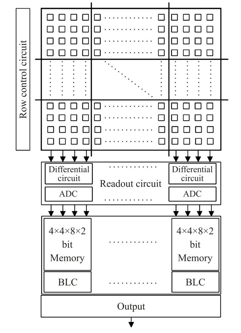
Fig.9 Overview of the overall system
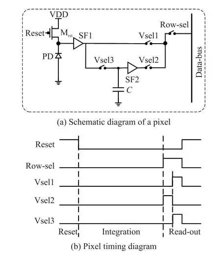
Fig.10 The architecture of pixel
Before integration,the PD is reset by the nMOS transistorMrst.After reset,Mrstis turned off and the PD terminal is floating.In the phase of integration,the PD starts to collect photo-generated charges.The read-out phase starts when Vsel2 is turned on Vsel1 and Vsel3 keep off,allowing the voltage across the capacitor C to be read out.After the Vsel2 is turned off while Vsel1 and Vsel3 is turned on,allowing the output of the SF1 to be read out and stored in the capacitor C.The pixel is then reset again,and the next frame starts.
Each column-level architecture is composed of a differential processing circuit,an ADC,a digital memory,a BLC encoder and an output interface circuit.The block diagram of the column-level architecture is shown in Fig.11.The differential processing circuit is implemented in the analog domain.The function of the differential processing circuit is to calculate the difference valuebetween the pixel of the current frame and the previous frame,and then outputXand.The digital values ofXandafter the ADC conversion are stored in the memory.

Fig.11 Block diagram of the column-level architecture
In the BLC processing circuit,the maximum number of bits required to represent the difference in the block is calculated.If the number of bits is less than 7,the differences in the memory are encoded by difference mode in the BLC circuit directly.Otherwise,the original pixel values are encoded by the pixel mode.The calculation of the pixel differences is performed in the readout phase,and these differences are converted to digital form.Compression coding is performed in the BLC digital circuit,and all blocks in a column share a memory to store digital values,which significantly reduces the area overhead of digital storage.
3.2 Experimental results
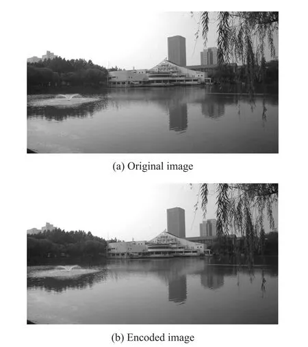
Fig.12 Frame 1 of the sample video

Fig.13 Frame 9 of the sample video
The resolution of the sample video “Fountain in The Lake” is 1280×720.In this experiment,the 4×4 block is set,while the threshold 63 is selected for encoding the differences.Fig.12 shows the original and encoded images of the first frame in the sample video.When the pixel array samples the first frame of image,the pixel values of the previous frame saved in the pixel array are all 0.Therefore,the pixel values used for encoding are equal to the pixel values in the original image.After the first frame is encoded,the pixel array always holds the pixel value of the previous frame.Fig.13 shows the original image and the binarization image in frame 9 of the video sample.The larger the difference,the brighter the pixel in these encoded frames.However,the differences in the encoded image are exceedingly small,which cannot clearly show the characteristics of the encoded image.Image binarization is used to reflect the characteristics of the encoded image.Set the absolute value of the differences in the encoded image greater than 10 to 255.The absolute value of a differences less than 10 are set to 0.The differences after binarization are displayed in the form of grayscale image,as shown in the Fig.13(b).In the sample video,the willows and fountains are swaying.The pixel values corresponding to the willow tree and the fountain in the frame are changed significantly.Therefore,the outline of the willow tree and the fountain could be seen clearly.
The compression ratio and BPP for the sample video from frames 1 through 9 are listed in Table 4.The image data used to encode the first frame is the same as the original image data,and prefix is added to encoded data during encoding.So,the first frame is encoded with more data than the original.All frames following the first image are compressed efficiently.The simulation result of the sample video in terms of compression rate expressed in BPP is 2.85.

Table 4 Compression ratio&BPP of sample video
Table 5 compares the performance of the proposed scheme presented in this paper with the image sensors with compression function reported in the Ref.[12,19,24-25].It should point out that the comparison of different sensors is not obvious as the target performance is different for different designs.Therefore,the best compression rate reported in the literatures are used to compare with the compression effects in this paper.Although a higher compression rate is achieved in the sensors with lossy compression,it sacrifices image quality.The algorithm proposed in this paper achieves a considerable compression rate without loss of image quality.

Table 5 Performance comparison
Table 6 shows the comparison of video compression ratio between the proposed algorithm and related work in Ref.[26-28].Compression ratio means the percentage of the amount of data reduced by the compressed data compared with the uncompressed data.All of these works realize video compression by encoding the difference between two frames.

Table 6 Comparison with related working compression ratio
4 Conclusion
In the paper,a video compression algorithm based on inter-frame pixel difference and BLC coding scheme is proposed.The problem of on-chip video compression is addressed.The solution used in this work is to implement a differential operation in the analog domain followed by a lossless entropy coder on chip.DPCM technique is chosen due to its simplicity and its lossless compression characteristic.Analog circuits are employed to decrease the complexity in the differential operation and because the function can be implemented with small analog circuit.The prediction operations in this technique are removed to further reduce the complexity of the circuit.
The basic idea of compressing difference is illustrated through the encoding solution,which is verified by 7 sample video coding experiments.Some simulations are carried out to optimize the proposed algorithm,the best block size and threshold are obtained.The experimental results show that when the pixel array block size is 4×4 and the threshold is 63,the best compression effect is achieved. The proposed algorithm achieves the compression gains up to 43.5%~78.5%in different contexts.In the absence of light,it is awfully close to the starry sky observation conditions to achieve a compression rate of 1.72 bits/pixel.In addition,the relationship between actual compression and theoretical compression in the “static scene” is analyzed.Since there is no completely static scene in the real world,the socalled static scene compression rate will be slightly higher than the theoretical value.
5 Acknowledgments
This work was supported by the National Key R&D Program of China(2019YFB2204202).