Characteristic Analysis and Harmonic Feature Identification of Micro-Vibration on Flywheels
2021-04-08 11:08:52YINXianbo尹顯波SHENGXiaowei盛曉偉XUYangSHENYan
YIN Xianbo(尹顯波), SHENG Xiaowei(盛曉偉), XU Yang(徐 洋), SHEN Yan(申 妍)
College of Mechanical Engineering, Donghua University, Shanghai 201620, China
Abstract: To avoid the negative effects of disturbances on satellites, the characteristics of micro-vibration on flywheels are studied. Considering rotor imbalance, bearing imperfections and structural elasticity, the extended model of micro-vibration is established. In the feature extraction of micro-vibration, singular value decomposition combined with the improved Akaike Information Criterion (AIC-SVD) is applied to denoise. More robust and self-adaptable than the peak threshold denoising, AIC-SVD can effectively remove the noise components. Subsequently, the effective harmonic coefficients are extracted by the binning algorithm. The results show that the harmonic coefficients have great identification in frequency domain. Except for the fundamental frequency caused by rotor imbalance, the harmonics are also caused by the coupling of imperfections on bearing components.
Key words: flywheel; micro-vibration; sigular value decomposition comined with the improved Akaike Information Criterion (AIC-SVD); harmonic coefficient; binning algorithm
Introduction
In addition to the space environment, satellites are also disturbed by the internal airborne on orbit[1]. The internal disturbance sources of satellites mainly include flywheel system, solar cell array drive mechanism, cryogenic cooler, camera swing mirror mechanism and thruster,etc. Among them, the micro-vibration of flywheel system has the greatest interference to satellites[2]. Micro-vibration refers to the low-intensity mechanical vibration or disturbance of spacecraft in microgravity environment. It usually occurs in the range of 1 Hz to 1 000 Hz. With a small amplitude, the bandwidth and long duration, micro-vibration is difficult to be suppressed or compensated by the attitude adjustment mechanism[3]. Through the cabin platform, it decreases the pointing accuracy and attitude stability of satellites[4].
To reduce the adverse effects of micro-vibration, the characteristics of micro-vibration on flywheels are studied and analyzed. Through the experiment method, Mastersonetal.[5]derived the steady-state empirical model of micro-vibration. Considering the resonance, Zhaoetal.[6]introduced the amplification factor to optimize the steady-state empirical model. On this basis, they carried out disturbance comparisons of flywheels under rigid and flexible installation conditions. As for the characteristic analysis of micro-vibration, the binning algorithm is widely used to extract feature parameters[5-7]. Unfortunately, there are still problems such as poor adaptability and large deviation in signal processing. Based on the vibration test of flywheels, Sunetal.[8]improved the identification accuracy of the amplitude coefficient by the energy compensation method. Mbaetal.[9]used stochastic resonance technology to extract the weak pulse characteristics of micro-vibration, which achieved the purpose of fault diagnosis.
To further discuss the micro-vibration characteristics of flywheels, the dynamic extended model was established based on the micro-vibration mechanism. After preprocessing by singular value decomposition combined with the improved Akaike Information Criterion (AIC-SVD), the binning algorithm achieves more accurate harmonic extraction. Furthermore, the corresponding harmonic disturbance source can be easily identified through the feature parameters.
1 Micro-vibration Mechanism
1.1 Flywheel structure
As shown in Fig. 1, the flywheel is composed of a brushless direct current (DC) motor, a support shaft, a rotor, bearings, a housing and a base. The magnetic torque generated by the coil stator drives the rotor. Through the mounting seat, the base is fixed on the satellite platform. According to the law of conservation of angular momentum, the flywheel controls satellite attitude and balances space disturbances[10].
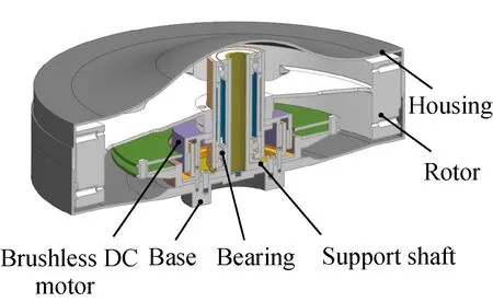
Fig. 1 Structure of flywheels
1.2 Micro-vibration source
The micro-vibration of flywheels originates from active disturbances, structural disturbances and other disturbances. Active disturbances are mainly caused by rotor imbalance, bearing imperfections and electromagnetic torque fluctuation. Structural disturbances are caused by elasticity of rotor or shell. Meanwhile, flywheels are also affected by friction, lubrication or imperfect factors[11].
Due to the influence of structural design and material inequality, there are some errors between the rotating shaft and the inertia axis. The errors result in static imbalance and dynamic imbalance of the rotor. As shown in Fig. 2, the equivalent massmsandmdare used to simulate the static imbalance and the dynamic imbalance[12].

Fig. 2 Illustration of rotor imbalance
Through the support bearing, the disturbances generated by rotor imbalance produce the fundamental harmonic. In addition, bearing components also produce impact pulses because of their own imperfections during operation, as shown in Fig. 3. Substituting the bearing parameters into the frequency formulas[13], the relationship between the pulse frequencies and the rotational frequencies can be obtained. In Table 1,fois the rotation frequencies of the outer ring, andfiis the rotation frequencies of the inner ring.fIRI,fORI,fCRandfBIcorrespond to the pulse frequencies caused by the inner race, the outer race, the cage and the ball, respectively. In a single operating cycle, the imperfect position of the rolling element contacts with the inner and outer rings respectively. Therefore, the pulse frequencyfBIis twice as much as the rotation frequencyfBS.

Fig. 3 Illustration of imperfections on bearing parts

Table 1 Impulse frequency of imperfections on bearing parts
2 Modeling of Micro-vibration
Considering the imbalance of the rotor and the bearing imperfections, the micro-vibration of flywheels is assumed to be a series of discrete harmonics proportional to the square of the speed. The steady-state empirical model can capture the harmonic features of flywheels. Lacking the consideration of structural elasticity, it performs in bad agreement with high order harmonics. To reflect the elastic characteristics of the bearing support, the flywheel is modeled according to the dynamic theory. The angular contact ball bearing is equivalent to the stiffness-damper connected to the supporting shaft. Considering the rotor imbalance, the rotor-bearing model with five degrees of freedom is constructed, as shown in Fig. 4.

Fig. 4 Five degrees of freedom model for rotor-bearing
Lagrange’s equation is used to derive the system motion differential equation

(1)

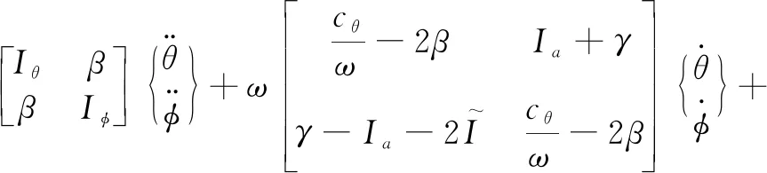
Considering bearing imperfections, the five degrees of freedom model for rotor-bearing is improved by combining with the steady-state empirical model. The model is given as

(2)
(3)

I always waited for Jennifer and Amy after classes, so we could walk together to our next class. Amy and Jennifer chatted by Jennifer s desk as Jennifer packed her books up and I waited by the door. Sometimes when they left, they d walk right past me. No Thanks for waiting. No Sorry we took so long. It was as if they couldn t even see me. Yet I still waited after every single class.
According to Eqs. (2) and (3), the main modes of the rotor bearing system can be obtained. Ignoring the system damping, the radial translation frequencyfr, the axial translation frequencyfa, and the swing frequencyf1, 2are respectively
(4)
(5)
(6)
Substituting the parameters of Table 2 into Eqs. (4)-(6), the relationship between the structural modal frequencies and the rotating speed are obtained, as shown in Fig. 5. In Fig. 5,frandfaare 455 Hz and 197 Hz, respectively, which remain constant with the speed change. Due to the gyroscopic effect of the rotor, the swing mode can be divided into forward precessionf1and reverse precessionf2. Among them,f1increases with the rotating speed, butf2is inversely proportional to the rotating speed. Within the operating speed, the structure mode has no interaction with the fundamental frequency.
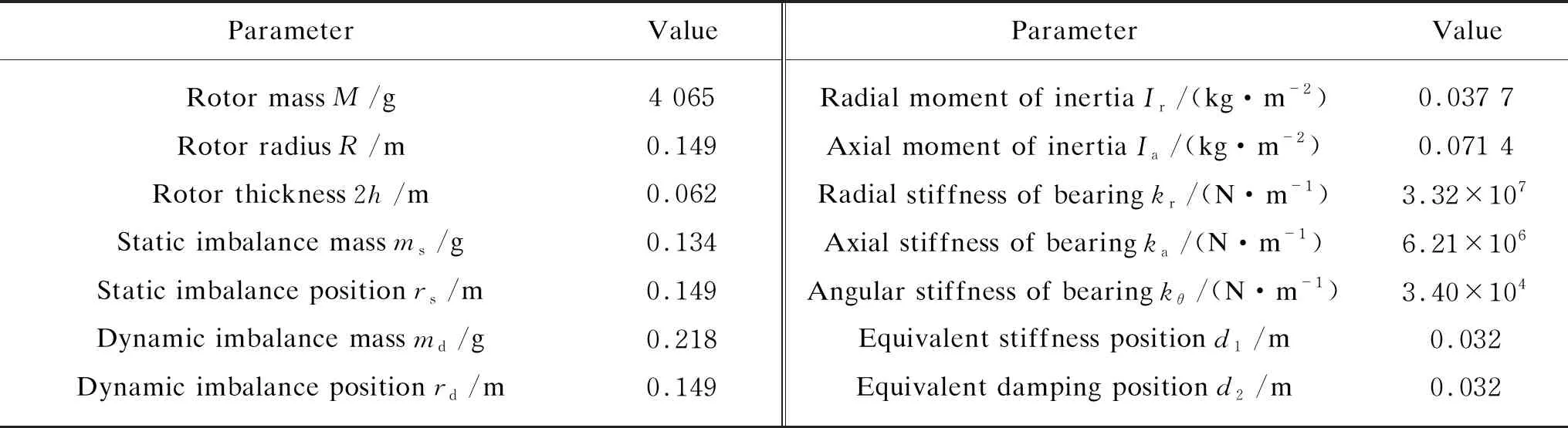
Table 2 Structural parameters of the flywheel

Fig. 5 Campbell diagram of micro-vibration on the flywheel
3 Harmonic Feature Extraction
3.1 Extraction method
In the extended model of micro-vibration, the harmonic coefficients can directly reflect the components of harmonics. Using the binning algorithm to extract the features, the corresponding disturbance sources can be identified. As shown in Fig. 6, the vibration component signalsΩuunder the speedΩis collected. After noise reduction processing, the peak values (fpeak,Apeak) ofxΩuare extracted in the spectrum. In addition to harmonic disturbances,fpeakalso includes some structural modes. To extract the frequencies of harmonic features accurately, the modal frequencies solved by the extended model are judged to be removed. After normalizing harmonic frequencies, the toleranceεand the peak ratioPkare set to obtain effective harmonic coefficientshui.

Fig. 6 Flow chart of binning algorithm
In the binning algorithm, reasonable preprocessing can get double results with half the effort. As we all know, the acquired signals inevitably are mixed with interference noise. For flywheel vibration signals, the current noise reduction processing is mainly based on the peak threshold denoising[5]. Affected by uncertain parametersNσ, the method of peak threshold denoising is prone to over-denoising or under-denoising. As a result, the stability and accuracy also decrease in feature extraction. To extract the harmonic coefficients of vibration effectively, the denoising method named AIC-SVD is used to improve it.
3.2 Denoising by AIC-SVD
Based on the singular value decomposition (SVD) of Hankel matrix, the signal can be decomposed into a simple linear superposition of a series of component signals[14]. For additive noise, an advantage of this decomposition is that the main components can be retained directly to achieve the purpose of denoising. According to the principle of matrix orthogonal transformation, the Hankel matrixAcan be obtained by singular value decomposition[15].
The singular valuesσicontain all the characteristic information of the signal. To effectively separate the main characteristic component, the orderkof the singular values is determined by the AIC. AIC is an estimated measure of the fitting goodness of statistical models. The function of AIC contains the terms of parameter fitness and inserted bias correction. When the sum of the two terms is the smallest, it means that the function balances the two factors to get the best estimate of the effective order[16].
In addition to white noise with uniform power, there are also colored noises produced by friction or electromagnetic interference in micro-vibration[17]. To smooth the interference components in the background of colored noise, the diagonal loading technique[18]is used to correct the singular value
(7)
Substituting the modified singular values into the function of AIC, the improved decision functionAimpand the effective orderkare respectively
2d(2q-d),
(8)
(9)
whereNrepresents the number of signal sampling points,nis the row of the Hankel matrixA,d=1, 2, …,n-1 denotes the number of sources, andqis the number of non-zero singular values.
The flow chart of AIC-SVD denoising method is shown in Fig. 7. Firstly, the Hankle matrix of the measured signal is constructed and solved by SVD. Then the improved AIC is performed to determine the effective order of the singular values. Finally, Through the inverse operation of SVD and the average method, the frontkorder components are reconstructed to obtain the denoised signal.

Fig. 7 Flow chart of signal denoising method using AIC-SVD
4 Analysis of Micro-vibration
4.1 Test of micro-vibration
The micro-vibration test of the flywheel is carried out based on six component force measurement method, as shown in Fig. 8(a). Through the transfer tooling, the disturbances of the flywheel are transmitted to the Kistler force platform. Meanwhile, the built-in sensors of the platform acquire signals in real time. Four piezoelectric three-dimensional force sensors are selected to collect voltage signals. There are evenly distributed between the top plate and the bottom plate of the platform, as shown in Fig. 8(b). Through the charge amplifier, the vibration signals collected by the sensors are transmitted to the data acquisition system. Finally, the tested signals are processed and displayed on the computer.

Fig. 8 Micro-vibration test of the flywheel
The disturbance force of environment is less than 0.2 N, and disturbance torque is less than 0.01 N·m. The test result meets the requirements of the force measuring system for the environment. Within the working speed range, the acquisition is performed every 200 r/min interval. The spectrum waterfall diagrams of acquired signals are shown in Fig. 9. It can be seen that the axial disturbance momentMzis very small and could be neglected. Vibration mainly occurs in the radial directionFx, the axial directionFzand the radial directionMx.

Fig. 9 Waterfall diagrams of the flywheel
4.2 Harmonic identification
TakingFxas an example to carry out the analysis of noise reduction, the peak threshold values (DT) are calculated as shown in Fig. 10. In Fig. 10(a), the threshold values increase with the speed. However, there are sharp change occurs at 400 r/min and 1 800 r/min. Analyzing Fig. 10(b), it can be seen that the threshold values increase due to the shell mode of 131.5 Hz at 1 800 r/min. This leads to the loss of some important features, such as the 18 Hz harmonic caused by the bearing cage.
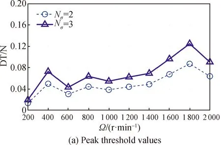
Fig. 10 Peak threshold denoising in Fx
To eliminate the adverse effects of noise, the vibration signals of the flywheel are processed by AIC-SVD and shown in Fig. 11. AIC-SVD can effectively retain the weak features in the signal. Among them, 435 Hz is the radial translation frequencyfrof rotor-bearing. The relative error between theory and experiment is 4.40%, which is mainly caused by structural damping. In addition, the axial translational frequency of rotor bearing is 195.5 Hz, and the relative error is 0.76%.
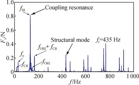
Fig. 11 AIC-SVD denoising in Fx
Furthermore, the energy of the denoised signal is analyzed. The energy ratio of the main component to the total signal is calculated, as shown in Fig. 12. After AIC-SVD denoising, the main feature energy ratio is 92.47%, and the corresponding root mean square error (RMSE)Rmis 0.022. Through comparison, the RMSE of AIC-SVD is far less than 0.074 and 0.124 from the peak threshold denoising. It shows that AIC-SVD has better adaptability and stability compared with the traditional method.
Synthesizing the vibration signals under all measured speeds, the structural modes are removed from the system. Based on AIC-SVD denoising and the binning algorithm, the harmonic coefficients of each direction are extracted. The obtained parameters are shown in Table 3. Combined with the vibration mechanism, it can be known that the denoised signals also contain frequencies offCR,fo,fBI,fORIand multi-harmonic coupling. In the directionxandθ, the flywheel is disturbed by 0.6 times harmonic caused by the bearing cage imperfections and fundamental harmonic caused by the rotor imbalance. The harmonic coefficients of 4.39, 4.98 and 7.13 are caused by the imperfections of rolling element, outer ring and inner ring respectively. Except structural modal factors, the micro-vibration in the directionzis mainly caused by the bearing imperfections.

Fig. 12 Energy ratio of main features in Fx
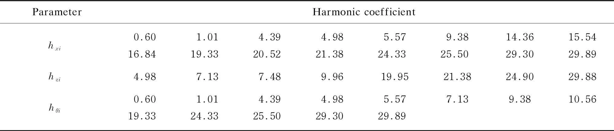
Table 3 Main harmonic coefficients of micro-vibration
5 Conclusions
(1) The harmonic disturbance, structural mode and coupling resonance are the main factors of micro-vibration on flywheels, accounting for 92.47% of the total energy. Therefore, the extended model of micro-vibration combining harmonic features and structural elasticity can better express the micro-vibration characteristics.
(2) The AIC-SVD denoising method is applied to the signal preprocessing of micro-vibration, which can effectively reduce the noise. Compared with the traditional peak threshold denoising, it has better stability and adaptability.
(3) Processed by AIC-SVD, the principal components of the micro-vibration signals have great identification in frequency domain. The analysis shows that the harmonics along radial direction and around radial direction are caused by rotor imbalance and bearing imperfections. And the harmonics along radial direction is mainly caused by bearing imperfections.
 Journal of Donghua University(English Edition)2021年1期
- Journal of Donghua University(English Edition)的其它文章
- Effect of Blending Ratio on Properties of Core Yarn and Fabric of Polysulfonamide (PSA)/Flame Retardant Viscose (FRV)/Conductive Filament
- Tensile and Electro-Mechanical Properties of Carbon Nanotube Film Twisted Yarn with Adjustable Diameter
- Metaphor Analysis Method Based on Latent Semantic Analysis
- Structures and Stability of Th(N6), Pa(N6), and U(N6)
- Structural Reliability Analysis Based on Support Vector Machine and Dual Neural Network Direct Integration Method
- Implicit Attribute Recognition of Online Clothing Reviews Based on Bidirectional Gated Recurrent Unit-Conditional Random Fields