Controlling the light wavefront through a scattering medium based on direct digital frequency synthesis technology*
2021-01-21 02:11:00YuanYuan袁園MinYuanSun孫敏遠YongBi畢勇WeiNanGao高偉男ShuoZhang張碩andWenPingZhang張文平
Chinese Physics B 2021年1期
Yuan Yuan(袁園), Min-Yuan Sun(孫敏遠), Yong Bi(畢勇),?, Wei-Nan Gao(高偉男),Shuo Zhang(張碩),2, and Wen-Ping Zhang(張文平)
1Center of Applied Laser,Technical Institute of Physics and Chemistry,Chinese Academy of Sciences,Beijing 100190,China
2University of Chinese Academy of Sciences,Beijing 100190,China
Keywords: optical transmission matrix, direct digital frequency synthesis technology, phase modulation,wavefront optimization
1. Introduction
Since the invention of the optical lens, the field of optics has not only had an impact on daily life but also in almost all areas of science and technology. With a conventional lens, typically made of transparent refractive materials, one can easily manipulate light with a large degree of freedom.However, it is difficult to control the optical near field after turbid media, where conventional optical components fail to access. The propagation of waves in the multiple-scattering regime is a very fundamental problem of physics with numerous applications ranging from solid-state physics and optics,to acoustics and electromagnetism.[1]
A deeper approach to the study of complex media lies in the transmission matrix (TM) retrieval. This matrix is a subpart of the usual scattering matrix as defined in Ref. [2] for instance. The knowledge of the TM brings more fundamental insight into the medium. One can for instance extract from the TM the single and the multiple-scattering components,[3]the backscattering cone,and the field–field correlations.[4]Experimentally,the TM can encapsulate the experimental imperfections induced by optical misalignment,surface curvature,lens aberrations, and non-uniform laser illumination. Measuring the TM of a turbid medium has shown potential in focusing,delivering images, controlling transmitted energy, subwavelength imaging,[5–18]and customizing speckle statistics.[19–21]Especially, the optimized wavefront of an illumination beam calibrated by the TM method generates a focus through random scattering media.If this technology is utilized in the laser TV, the light efficiency from the diffuser into the optical engine will be largely improved.
In the literature of measuring the TM, iterative approaches, like successive displays of Hadamard patterns or canonical patterns on a spatial light modulation (SLM), are usually adopted. The frequency-based focus optimization technique is one of the methods using canonical patterns,where each SLM phase element is modulated at a unique angular frequency and all the phase elements go through a 2π phase variation. By this method, different high-quality foci are obtained through a scattering medium. However, how to precisely generate successive phase patterns on a SLM with predefined frequency (i.e., the process of phase modulation)to fit the characteristics of the SLM device has not been illustrated in detail. An effective phase modulation technology is important for obtaining a correct result. As known, the SLM is an 8-bit digital device, and the gray values have a range from 0 to 255. The minimum increment of the phase both in each pixel and in adjacent pixels is 1 graylevel. Different from Hadamard patterns and four phases method,[5,22,23]the frequency-based focus optimization technique makes the increment of each phase element be decimals, varying with the frequency on each SLM element, and the phase values increase with an iterative process. If these decimals are not properly truncated with non-fitting values cropped,the deviation will gradually accumulate with the iterative process and finally fail to obtain the correct result. To avoid cumbersome truncation rules for huge phase values in the experiment, we introduce the direct digital frequency synthesis (DDS) technology to modulate each SLM phase element.
In this paper,we illustrate the principle of the DDS technology and its application in SLM phase modulation. Based on full-field interference and the DDS technology, we determine the required wavefront through a Fourier transform of the detected signal and obtain a high-quality focus of coherent light through a 2 mm thick 120 grit diffuser. We expect this wavefront shaping method alongside the DDS technology to reduce speckle and power consumption in laser TV or laser holographic display in our further study.
2. Method
2.1. Procedure to measure a transmission matrix
where smis the complex amplitude of the optical field used as a reference in the mthoutput mode. The phase φnis modulated at an angular frequency ωnand goes through a 2π phase variation, resulting in Imvarying. When one phase pattern is loaded onto the SLM,then projected onto the scattering sample, the corresponding output of the sample is imaged by the CCD. When a series of output intensity Imat the target position is recorded and Fourier transformed, the third term in Eq. (2) can be decoupled from the others and the optimized phase pattern is determined. Then we address the optimized phase pattern onto the SLM,a clear focus can be obtained.
We divide the procedure of measuring the TM into three steps. Assuming the SLM consists of a K×L array of pixels,the SLM pixels are divided into two groups, one group modulates the impinging wavefront (signal beam) with the DDS technology,while the other part remains fixed in order to provide controlled reference beams.
In step 1, each SLM phase element corresponding to the signal beam is modulated at a unique frequency,ω1,ω2,ω3,...,ωn,...,ωN, resulting in each SLM phaseshifted by φ1,φ2,φ3,...,φn,...,φN. The SLM frame is successively updated and loaded onto the SLM constantly, and finally,4N speckle patterns are recorded by the CCD.The detected target signal is Fourier transformed,and the phase values at the corresponding frequencies are determined.In step 2,after the phase corresponding to the first group is determined,the other group is modulated while the first group is maintained at the newly determined phase values. In the same way,we obtain 4(K×L-N)speckle patterns by the CCD.The detected target signal is Fourier transformed,and the phase value at the corresponding frequencies in the second group is determined. In step 3, with the measured phase profile in the first two steps loaded onto the SLM, a bright round focus will be observed on the CCD at the target position.
2.2. Direct digital frequency synthesis technology
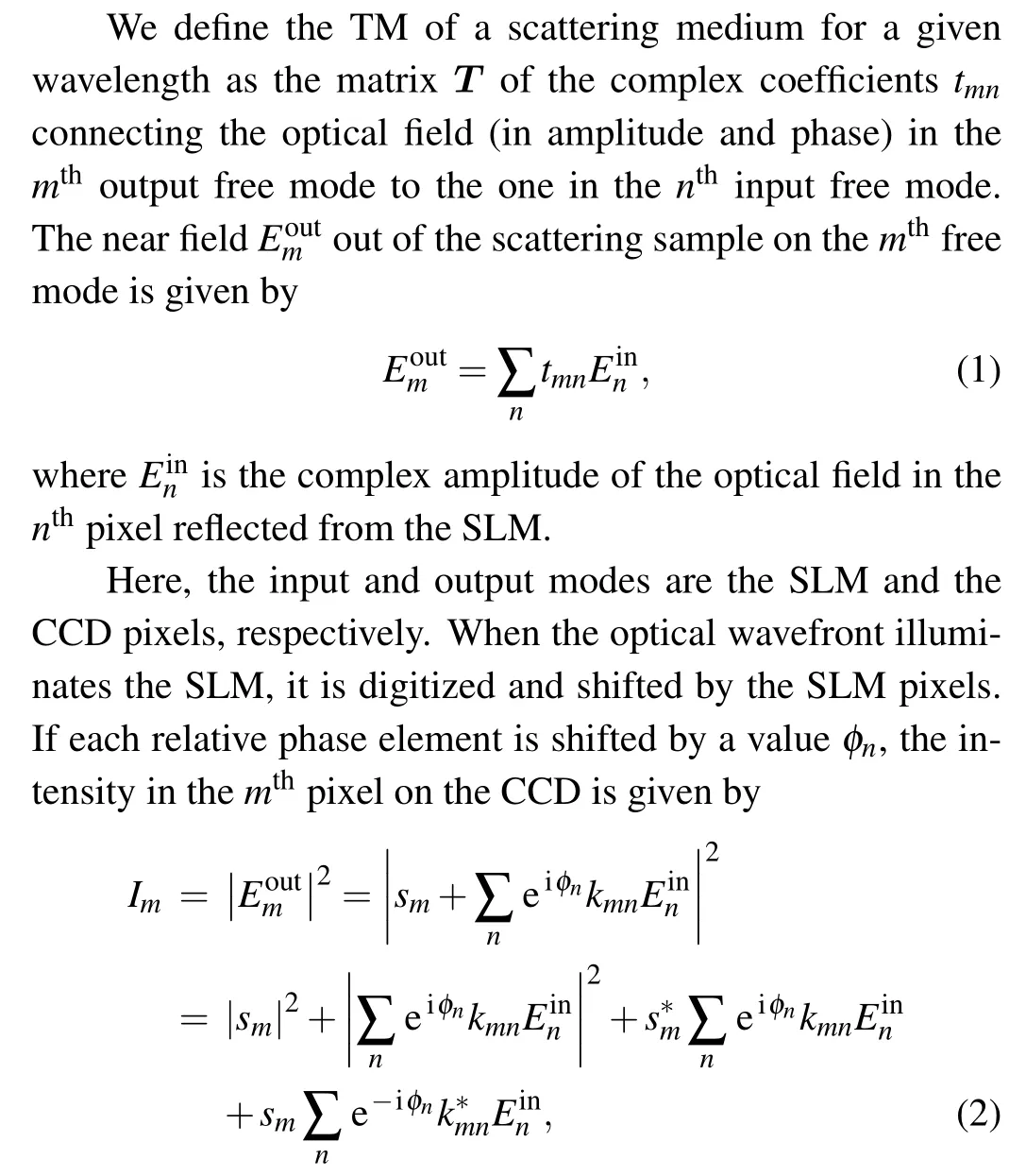
We exploit the DDS technology to modulate the SLM phase element.[24]The frequency obtained by DDS technology is expressed as
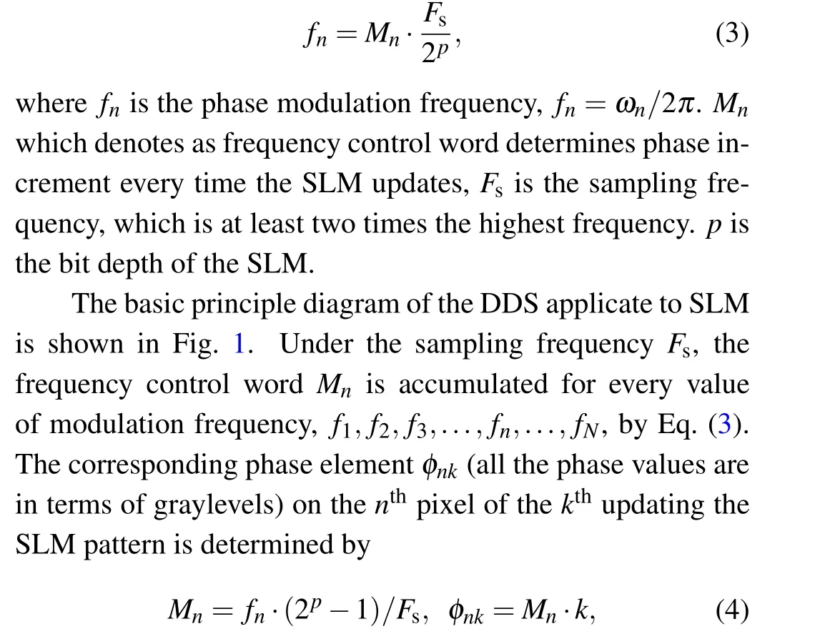
where k ranges from 1 to L (L=4N). Different frequency control word Mnwill cause different phase increments of the SLM pixel(i.e.,having different modulation frequency fn). It should be noted that φnkis cropped into the range of[0, 255]before it is shown on the SLM. Figure 2 simulates the phase modulation result using the DDS technology.Figure 2(a)illustrates the phase modulation on the first pixel of 4N successive SLM patterns. Figure 2(b)shows the magnification of the first 10 periods. With the DDS technology,the SLM phase is accurately and fully modulated in the range of[0,255].
Fig.1. The basic principle diagram of the DDS applicate to the SLM.
Fig.2. Simulation of phase modulation with the DDS technology.
3. Experimental setup and results
3.1. Experimental setup
In our experimental setup,illustrated in Fig.3,a linearly polarized monochromatic laser beam with a wavelength of λ =632.8 nm is expanded and uniformly illuminates a phaseonly reflective SLM(Holoeye Pluto-2). The modulated beam from the SLM goes through a 4-f system and is projected onto a surface of a diffuser via an objective lens(100×,NA=0.85,Nikon, Japan). A 2 mm thick 120 grit ground glass diffuser(Thorlabs, DG10-120) is used to randomly scatter the light before it reaches the focal plane. The diffusing surface faces the 0.45 NA objective lens. The light-transmitting through the diffuser is collected using an objective lens(20×,NA=0.45,Nikon,Japan)and then projected on a camera(Manta G201B).Experimentally, we record the speckle pattern well above the Nyquist limit per speckle grain along each axis.
To avoid cross-talk between neighboring SLM pixels,20×20 pixels are grouped to form one macropixel. We use a square array of 30×30 macropixels in the central part of the phase modulating region of the SLM. We vary, with a z-axis translation base,the position of the first objective to obtain the highest intensity enhancement, with respect to the 0.45 NA objective kept at a fixed position. The calculated phase by Fourier transform of the detected signal on the CCD is feedback to the SLM by programming instructions. In addition,owing to imperfections in the pixels of the SLM,a correction pattern is superimposed onto the optimized wavefront to allow pixel shifting.
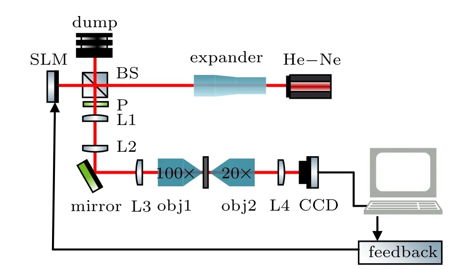
Fig. 3. Schematic of the apparatus. BS: beam splitter; P: polarizer;L1–L4: lens;obj1,obj2: objective len.
3.2. Results and discussion
Firstly, some of the varying intensity values on the first CCD pixel are tracked in Fig. 4, which helps to identify the response of the SLM device. When the effective oscillating intensity is Fourier transformed, the optimum wavefront can be obtained. Figure 5(a) is the pattern that is transmitted when a plane wave is focused onto the sample, a 2 mm thick 120 grit ground glass diffuser. The light forms a typical random speckle pattern. Based on the optical setup and the algorithm described above, we measure the TM of the sample. The row and column of the conjugated TM are the output and input channels, which correspond to the pixel indexes of the CCD and SLM. Figure 5(b) shows the reshaped 2-D optimized phase map of the 4950throw of the conjugated TM,i.e., compensating for the random phase through the sample to focus the transmitted light at (50, 50) on CCD, as shown in Fig. 5(d). Subsequently, we retrieve the phase map from the 1920thand 7980throws of the conjugated TM. Then we measure a clear focus at (20, 20) and (80, 80) on the CCD plane, separately, in Figs.5(c)and 5(d). In fact, by adjusting the target optimal phase map used as feedback, it is possible to observe a bright round focus at any target position.
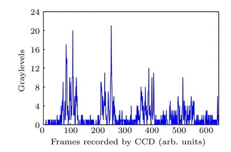
Fig.4. Varying intensity on the first pixel recorded by the CCD.
We estimate the experimental SNR defined by the ratio of the intensity at the focus to the mean intensity of the speckle outside. In Figs.5(c)–5(e),the result of focusing on the single spot shows SNR=51, 48, and 51. From a theoretical point of view, monochromatic phase conjugation focusing through a multiple-scattering medium has been studied in Ref. [22].The general formulation for the enhancement of the focus is SNR ≈Ngrains, the total number of “information grains”, or degrees of freedom. In our experiment, Ngrainsis the number of pixels characterized by modulation frequency in the central region of the SLM,i.e., Ngrains=450. Using the theoretical formalism developed in Refs. [5,24], the effective SNR,caused by the effect of the reference beam,can be written as

where the dominating ratio γ is 50%,denoting that the fraction of the SLM used to be modulated. (1-γ)/γ is the effect of the reference beam which contributes as the noise at the focal spot. The experimental SNR of the focus in Figs.4(c)–4(e)is 28%, 27%, and 28% of SNRref. We attribute this difference to the inhomogeneous voltage-phase response function of the SLM pixels,phase digitization due to the 8-bit depth of SLM,and the intensity nonuniform.
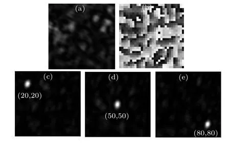
Fig.5. (a)Random speckle with a flat phase profile displayed on the SLM,(b-d) focus profile with the measured phase pattern displayed on SLM,(e)Fourier transform determined phase pattern.
Figure 6 illustrates that the full width at half maximum(FWHM) of the focus at (50, 50) is ~10 pixels of the CCD,or 44 μm, no matter on the horizontal X-axis or the vertical Y-axis. We also demonstrate that the size of the focus is independent of the number of the SLM pixels in use. In addition,although the SNR is significantly high,the sidelobes appear beside the central peak.These results from an incomplete control of the light. The number of the SLM pixels used is much lower than the number of modes that propagate through a scattering media. The uncontrolled modes generate a speckled background.
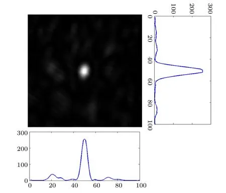
Fig.6. The FWHM of the focus at the center on the horizontal X-axis and the vertical Y-axis.
4. Conclusion and perspectives
To conclude,a DDS technology alongside a full-field interferometric method is demonstrated to have the excellent ability to focus the transmitted light through a 2 mm thick diffuser. It is the first time that the DDS technology is applied to modulating the SLM phase element,which skillfully modulates the SLM phase,minimizes the experimental error/noise,and finally makes the procedure of the TM simple time-saving and accurate. Using this algorithm, a relatively accurate TM is measured, resulting in the SNR of the focus nearly 50 and the FWHM about 44 μm. The total time for reconstructing the focus is 800 s. The results show that the proposed method has the potential in improving the light efficiency and compensation for the phase of speckle-noise on image or video in laser display and holographic display,where similar diffusers were inserted in Refs.[25,26]. In addition, this method can be applied in ghost imaging, customizing statistics of speckle, and biomedical adaptive optics.
Acknowledgment
The authors thank Jinhai Bai for valuable discussions and insightful suggestions.

- Chinese Physics B的其它文章
- Numerical simulation on ionic wind in circular channels*
- Interaction properties of solitons for a couple of nonlinear evolution equations
- Enhancement of multiatom non-classical correlations and quantum state transfer in atom–cavity–fiber system*
- Protein–protein docking with interface residue restraints*
- Effect of interaction between loop bases and ions on stability of G-quadruplex DNA*
- Retrieval of multiple scattering contrast from x-ray analyzer-based imaging*