The plume diagnostics of 30 cm ion thruster with an advanced plasma diagnostics system
2020-09-14 01:13:14
Plasma Science and Technology 2020年9期
Science and Technology on Vacuum Technology and Physics Laboratory,Lanzhou Institute of Physics,Lanzhou 730000,People’s Republic of China
Abstract
Keywords:electric propulsion,ion thruster,plasma diagnostics
1.Introduction
Flight demonstration verification was carried out successfully in 2012 on the 20 cm diameter LIPS-200 ion thruster,which is developed by Lanzhou Institute of Physics (LIP) [1].In order to achieve more thrust and specific impulse,the 30 cm diameter LIPS-300 ion thruster was developed on the base of LIPS-200 ion thruster [2].As a new ion thruster,the various performances of LIPS-300 ion thruster need in-depth study.Plume characteristics are important with regard to the satellites[3].First,the slow ions of plume is back to ion thruster or sputter satellite parts.Second,the sputtering material can deposit on satellite surfaces from the grids,or cathode and other electrodes of ion thruster,which can give rise to different emissivity,transparency,and so on.
Many variety of experimental methods have been developed and applied to study the plume effect,such as a Langmuir probe [4-6],Faraday probes [7-15],and a retarding potential analyzer (RPA) [16-18].To reveal the argon plasma characteristics of an electron cyclotron resonance (ECR) ion source,the plasma parameters were diagnosed using a bended Langmuir probe with the filament axis perpendicular to the diagnosing plane [19].In order to determine the plume characteristics,measurements of the BUSTLab MET thruster plume plasma are conducted using a single Langmuir probes and a Faraday probe [20].However,plume characteristics of LIPS-300 ion thruster are hardly studied.So plume characteristics of LIPS-300 ion thruster were studied by LIP’s ion thruster performance test facility (Chamber TS-6C) with an advanced plasma diagnostics system (APDS) in this paper.
2.Experimental apparatus
The APDS is composed of the following parts:probe rake,Faraday cup (FC) array,multi-grid retarding potential analyzer (MG RPA) array,triple Langmuir probes (TLP) and data acquisition.
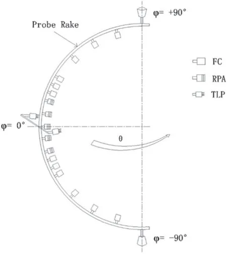
Figure 1.Illustration of the APDS mobile rack,probe rake is located θ=?90°.
2.1.Probe rake
The APDS probe rake is the mobile structure supporting 12 FC probes,five MG RPA probes,and two TLPs used to perform plasma plume investigation.An illustration of the APDS probe rack is shown in figure 1.
When it scans the plume of the ion thruster,the probes face the exit plane of the thruster indefinitely.Vertical position of the probes at the probe rack is represented by φ,and the horizontal position through the plume is represented by θ.Figure 1 shows the configuration of the APDS probe rack.
The APDS rake coordinate reference system is shown in figure 2.The 0° angle is on the thruster axis;the angular positions on the left of the thruster (on top view) are defined as negative angles,while the ones on the right are defined as positive.
2.2.FC array
The FC probe is built of a collector,usually a metallic cylinder,able to collect the ions coming from the plasma source,a polarized screen,acting as a filter for the electron,and an ammeter in series with the collector,used to measure the collected current.
The FC probe is usually used in array configurations.In the APDS,an array of 12 probes was used to perform a plume scan on a 1000 mm radius hemispheric surface in front of the thruster.The main output of an array of FC is the ion current distribution.A detail configuration and picture can be found in figure 3.For the FC collector (COL) and external shield(EXT SHLD),the Polarization ranges are?60-0 V.
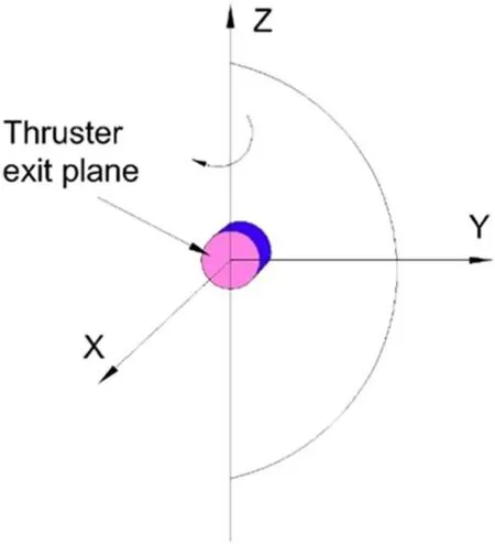
Figure 2.APDS probe rake coordinate reference system.

Figure 3.Faraday cup image.
The FC probes are arranged every 5°from φ=+20° to φ=+30°,and from φ=?30° to φ=?20°,every 15°from φ=+45° to φ=+75°,and from φ=?75° to φ=?45°,the radius of the probe rack is 1000 mm.
2.3.MG RPA array
The MG RPA is designed to measure the ion energy distribution in a plume of the ion thruster.These probes are arranged every 5° from φ=?15° to φ=+15° (?10° and+10° are alternative positions available).The MG RPA has two operation models:FC model and RPA model.Measuring current density uses FC model,while measuring ion energy uses RPA model.
The multi-grid configuration (figure 4) includes an external screen(S),usually floating with respect to the plasma potential,three polarized grids,named primary electron retarding electrode (PERE),ion retarding electrode (IRE),secondary electron suppressor electrode (SESE),and a collector (COL),connected with an ammeter.

Figure 4.MG RPA image.
The energy scan takes place in the progressive polarization of the IRE,which acts as an energy filter on the ions coming from the plasma source:The higher is the polarization voltage of IRE,the higher kinetic energy of the ions were collected by the collector (only the ions with a sufficient energy are able to pass IRE and reach the collector).In particular,the ion energy distribution is proportional to the mathematical derivative of the drained current to the applied retarding voltage on IRE.
The collector current(I)and voltage(V)can be written as[21]
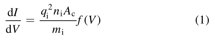
f(V) is ion energy distribution,Acis collector area,niis ion number density,qiis ion charge,miis mass of an ion.If we get the dI/dV distribution,then ion energy distribution can be known.
2.4.Triple Langmuir probe
The TLP consists of three electrodes P1,P2and P3placed in the plasma bulk to evaluate the main plasma properties as plasma voltage,plasma density and the electronic temperature.The TLP (figure 5) can instantaneously perform measurements without I-V characteristic curve thanks to the presence of two biased electrodes and an additional third floating electrode as potential reference.
The TLP installed in the APDS is triple electrode probes designed to be used in rarefied plasma,as the plasma located in front (at distance > 0.5 m).The TLPs are arranged symmetrical at θ=?5° and θ=+5°.
The TLP is based on a symmetrical configuration built using three identical cylindrical electrodes at different ‘static’potentials.Thanks to its ‘floating behavior’ it is possible to obtain all the plasma parameters with relatively little disturbance to the plasma and without voltage or frequency sweep or switching.This feature allows determining the instantaneous values of electron temperature,plasma density and plasma potential within a short time of the order of intrinsic response time of probe.
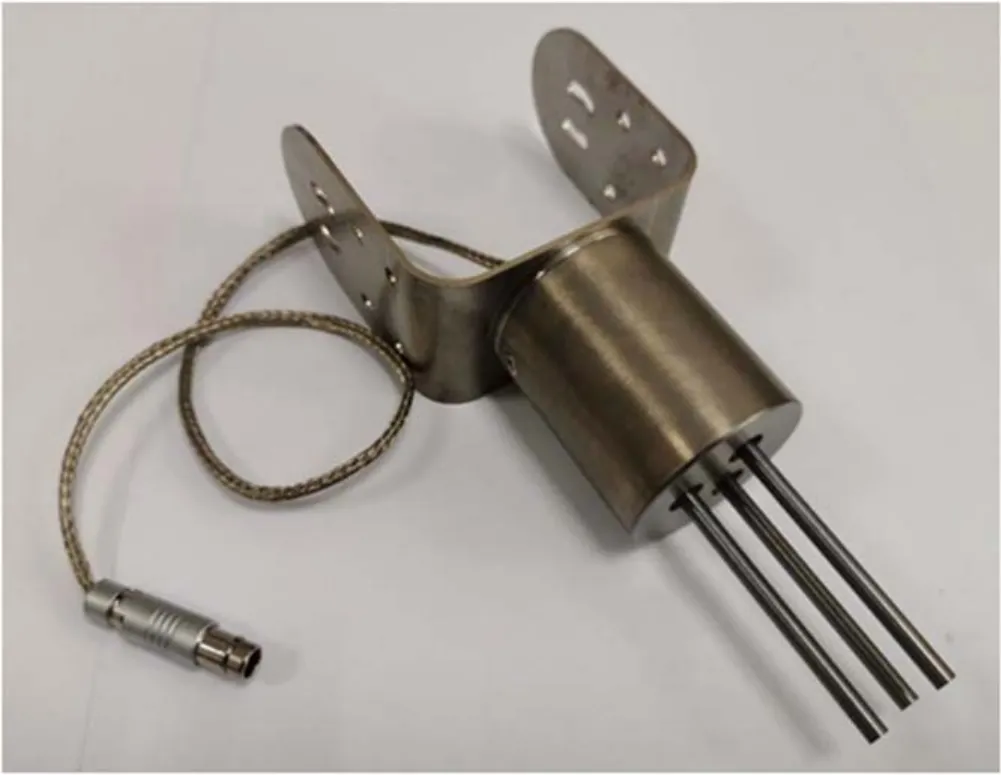
Figure 5.TLP image.
The electron temperature (Te) and electron number density (Ne) can be written as [22]
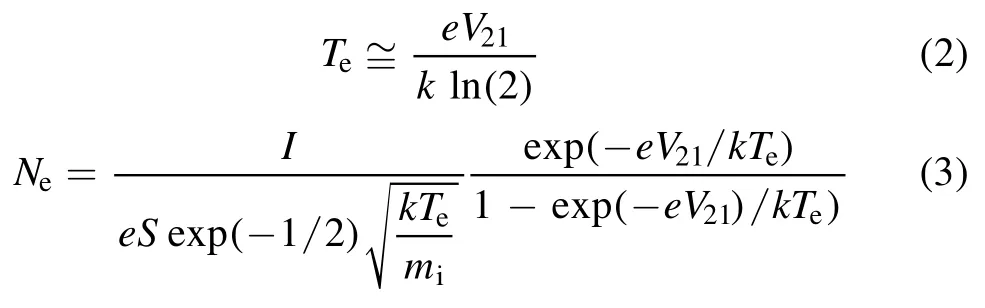
V21expresses the potential of probe electrodes P1and P2,k is the Boltzmann constant,e is the charge,S is the ion collection area of the probe,meis mass of an electron,miis the mass of the xenon atom,and I is the probe current is between probe electrodes P1and P3.
The plasma potential(VpREF)can be written as the below
V21expresses the potential of probe electrodes P1and P2,V1REFis the acquired voltage between probe electrode P1and the external reference,VpREFis the plasma potential,e is the charge,meis mass of an electron,and miis the mass of the xenon atom.
3.Results and discussion
3.1.Plume scan by FCs
The FCs allow the user to investigate the plasma plume in terms of ion current distribution.The scan surface is a hemispheric surface at 1000 mm distance from the ion thruster (placed in the center of the rake).The setting of the polarization power supplies is set by the desired polarization parameters for the collectors and the external shield of the FCs.
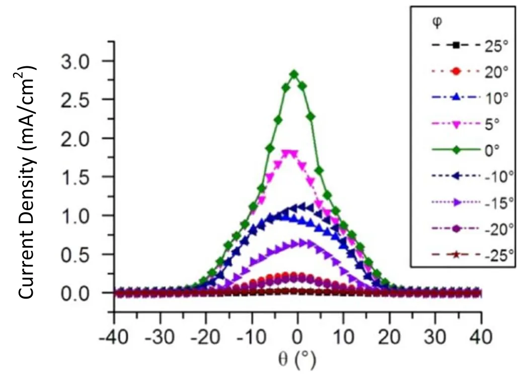
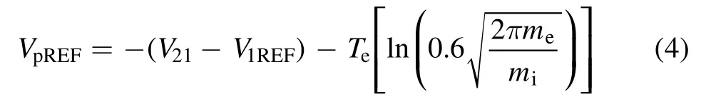
Figure 6.Beam current density versus scan angle.
The beam current density distribution is measured by an FC probe of the plume diagnostics system at the 5 kW normal operating condition.Figure 6 shows the beam current density distribution at different FC probe positions.It shows a sharply peak in the range of?20°-+20°.The max current density is 2.82 mA cm?2at 0°FC probe position.Beam current density decreases with increasing FC probe position or scan angle;and when the FC probe position or scan angle is greater than 20°,it clearly decreases.
Figure 7 shows beam current density distribution at different FC probe positions(0°,10°and 20°).A double‘wing’shape has been observed.This results from the charge exchange ion because of the base pressure of vacuum facility.Beam current density,dominated by charge exchange ion in greater angle,decreases with increasing scan angle.This is because high energy ions decrease clearly,resulting in less charge exchange ions.
3.2.Plume scan by MG RPAs
The MG RPA allows the user to investigate the plasma plume in terms of ion energy distribution.APDS is able to perform an energy scan by MG RPA in a single point set by the user.
The ion energy distribution is measured by RPA of the plume diagnostics system at the 5 kW normal operating condition.Figure 8 shows the ion energy distribution at different RPA probe positions.
The range of high energy ions is 993-1293 eV in small angle RPA probe position shown in figures 8(a) and(b).The results show that the max ion energy is close to 1193 eV.The high energy ions disappear,and the low energy ions appear at large RPA probe position in figure 8(c),the peak of low ion energy is about 31 eV.The ion current is dominated by the low energy ion.It is derived from charge exchange ions as a result of collisions between the high energy ions and background xenon atoms.
3.3.Plume measurement by TLPs
The TLPs allow the user to investigate the plasma plume in terms of electronic temperature,plasma number density and plasma potential.The APDS is able to perform two measurements at the same time with the TLP installed on board the rake.The measurements are performed in two symmetrical positions θ,±5°,with respect to the rake angle set by the user.
Figure 7.Beam current density versus scan angle.
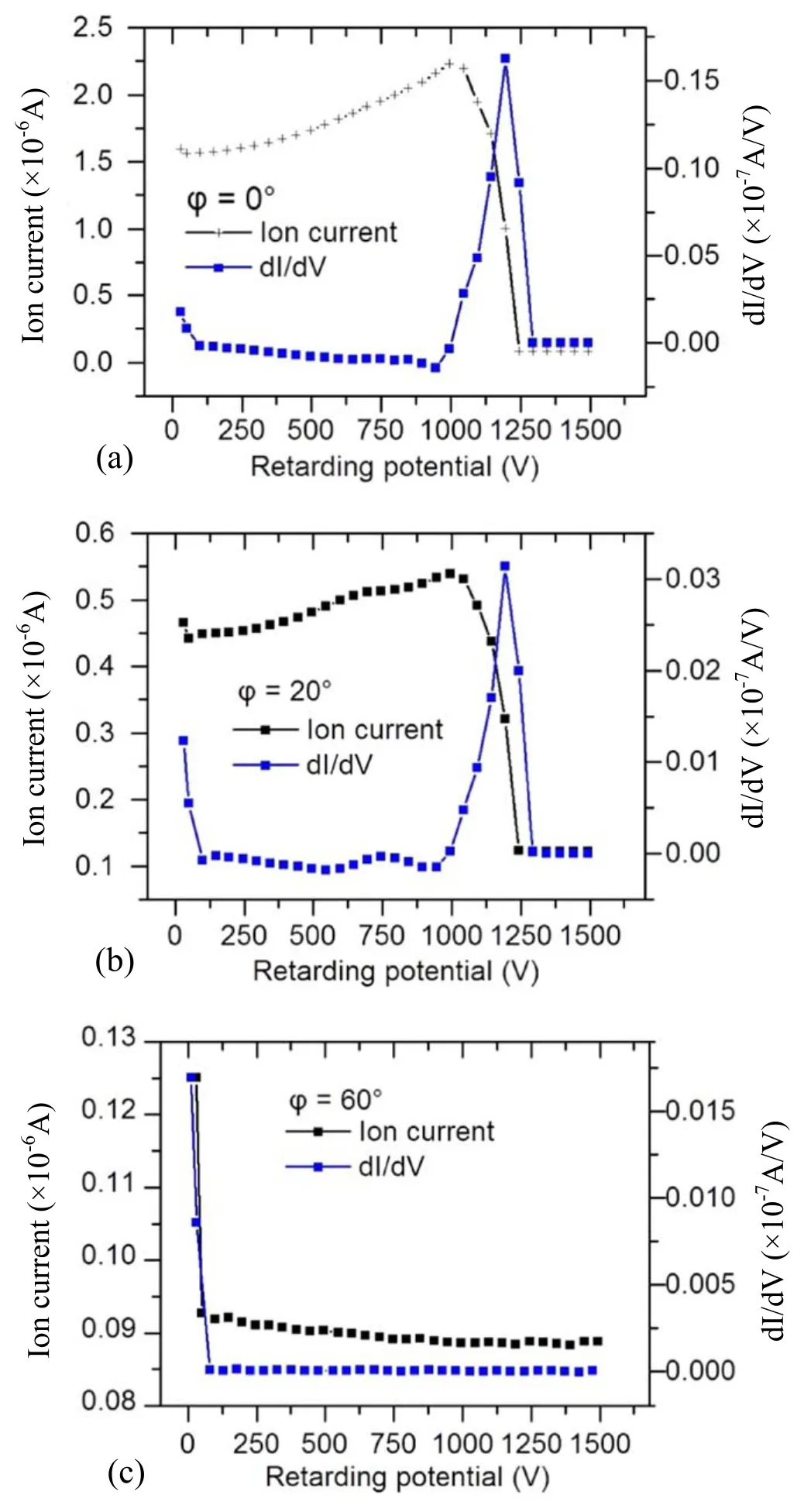
Figure 8.Ion energy distribution at different RPA probe positions.
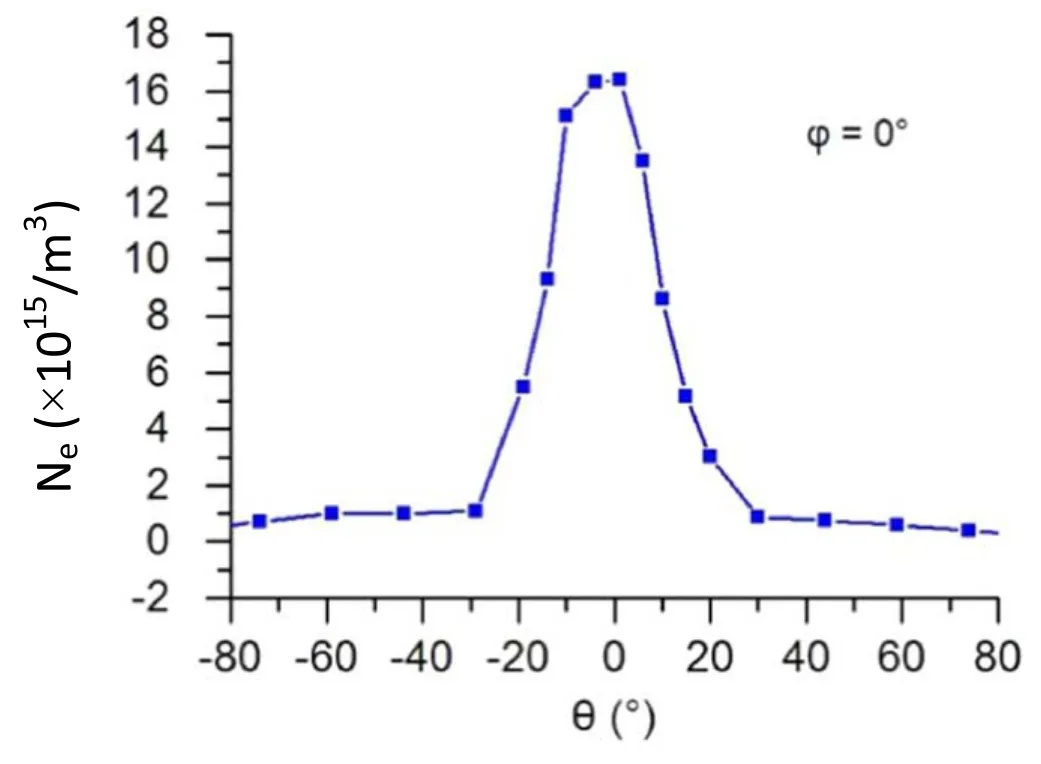
Figure 9.Electron number density versus scan angle.
The TLP#1 and TLP#2 (TLP#2 is backup) are installed respectively at θ=+5° and θ=?5° with respect to the rake centerline,and the acquisition angle refers to this line.
The electron number density is measured by TLP#1 of the plume diagnostics system at 5 kW normal operating condition.Figure 9 shows the electron number density distribution at different TLP scan angles.
Figure 9 shows the electron number density has a sharply peak in the range of?20°-+20°,the electron number density is up to 1.64×10¹⁶m?3.The electron number density decreases with increasing TLP scan angle,when TLP scan angle is greater than 20°,it decreases clearly.It has a similar shape with the beam current density distribution measured by FC probe.
4.Conclusions
The APDS is developed for ion thruster which allows for simultaneous in situ measurements of various properties characterizing ion thruster.The APDS is used to perform plasma plume investigation with 12 FC probes,five RPA probes array,and two TLPs for ion thruster or other electric thrusters.The APDS has been applied to LIPS 300 ion thruster from the LIP.
The beam current density,ion energy and electron number density of LIPS-300 ion thruster are measured by the plume diagnostics system at the 5 kW normal operating condition.The double ‘wing’ shape has been observed in beam current density distribution,which resulted from the charge exchange ion,because of the base pressure of vacuum facility.Ion current is dominated by the high energy ion in small angle RPA probe position.While high energy ions disappear in the greater angle RPA probe position,ion current is dominated by low energy ion.It is derived from charge exchange ions as a result of collisions between the high energy ions and background xenon atoms.The electron number density clearly decreases with increasing TLP scan angle.It has a similar shape with the beam current density distribution measured by FC probe.These data are very significant in the optimization design and space application of ion thruster.
Acknowledgments
The authors would like to thank Xin Ma and Shenglin Yang for their efforts in support of these measurements as well as Tianping Zhang and Ning Guo of the LIP Electric Propulsion Laboratory for their contributions in understanding the ion thruster plume diagnostics.
 Plasma Science and Technology2020年9期
- Plasma Science and Technology的其它文章
- Special issue on selected papers from CEPC 2019
- Life test research of a high specific impulse Hall thruster HEP-140MF
- Magnet stage optimization of 5 kW multicusped field thruster
- Application and development of the pulsed plasma thruster
- Simulation study on the influence of magnetic field in the near-anode region on anode power deposition of ATON-type Hall thruster
- Numerical simulation of the plasma acceleration process in a magnetically enhanced micro-cathode vacuum arc thruster