Femtosecond enhancement cavity with kilowatt average power?
2019-04-13 01:14:28JinZhang張津LinQiangHua華林強ShaoGangYu余少剛ZhongChen陳忠andXiaoJunLiu柳曉軍
Chinese Physics B 2019年4期
Jin Zhang(張津),Lin-Qiang Hua(華林強),Shao-Gang Yu(余少剛),Zhong Chen(陳忠)and Xiao-Jun Liu(柳曉軍)
1.Introduction
Extending the wavelength of optical frequency comb to extreme ultraviolet(XUV)region has attracted a great deal of attention since XUV comb provides a promising tool in precision spectroscopic measurements below 100 nm.[1–12]The advance in XUV comb technology will pave the way for measuring narrow atomic transitions,e.g.,the 1S-2S transition of He at 120nm,[13,14]He+at 61nm,[15,16]and Li+at40.7nm,[17,18]in the XUV region.These transitions are important not only in testing quantum electrodynamics(QED),[16]but also in testing the variation of the fine structure constant.[18]However,building an XUV comb is confronted with one major difficulty:no suitable laser medium in the solid or liquid phase is currently available.In order to overcome this problem,intense femtosecond laser driven high-order harmonic generation(HHG)with noble gases is adopted to realize the wavelength conversion.[1,2]
As well studied both in theory and experiment,a laser intensity above 1013W/cm2is needed to realize an efficient HHG process with noble gas atoms.[19]This intensity can be easily achieved by focusing a several-mJ femtosecond laser pulse to a radius of tens ofμm.However,these lasers always operate at a repetition rate ranging from a few Hz to several kHz.This feature makes the comb structure hard to be resolved since the carrier-envelope offset(CEO)frequency f0sometimes can be as wide as 200 kHz.[20]Usually,the repetition rate frof the optical frequency comb is~100 MHz,resulting in a dramatic decay of single pulse energy with same average power of kHz lasers.Therefore,it becomes necessary to enhance the laser power from high-repetition-rate IR optical frequency comb by using,e.g.,a femtosecond enhancement cavity(fsEC),to achieve this requirement.
In this paper,we report our recent progresses in building a fsEC on kilowatt level average power,with the aim of realization of intracavity HHG and extension of the wavelength of optical frequency comb from infrared to extreme ultraviolet.We are able to achieve an intracavity average power of 6.08 kW and the corresponding buildup is 225.After introducing noble gas of Xe into the focus region,clear sign of plasma has been observed.The generated HHG is also coupled out from the fsEC using a sapphire plate.
2.Experimental setup and results
The principle of fsEC is similar to that of continuous wave(CW)enhancement cavity.Considering that a CW laser beam propagates in an enhancement cavity,the phase shift of the laser field after the beam travelling one round trip in the cavity is φ = ωcw·L/c,where ωcwis the carrier frequency of incident laser,L is the length of cavity,c is the speed of light.If the phase shift is an integer multiple of 2π,the intracavity field will constructively interfere.This can also be understood in frequency domain:the carrier frequency of the CW laser matches with one of the resonance frequencies of the fsEC.However,different from CW laser with only single mode,optical frequency comb with broad spectrum has~106modes.This feature makes the situation much more complex.For a femtosecond optical frequency comb,the optical frequency f of any mode can be represented as:

where m is a large integer(~106).This means that the modes of optical frequency comb sit on a series of evenly spaced points in frequency domain.Similarly,the resonance frequencies of an fsEC are also evenly spaced in frequency domain.Therefore,in order to enhance all modes of optical frequency comb,the following three conditions have to be met:(i)the free spectral range(FSR)of the fsEC has to be the same as the repetition rate of the optical frequency comb;(ii)the CEO frequency of the optical frequency comb is properly adjusted,so that the evenly spaced comb modes are exactly matched with the resonance modes of the fsEC;(iii)the intracavity dispersion has to be compensated.These conditions can also be described in the time domain:i)the pulse after travelling one round trip in the cavity has to be overlapped with the next pulse;ii)the phases of the two overlapped pulses have to be identical;iii)the envelope of the circulating pulse has to be the same.With these conditions satisfied,the femtosecond pulses can be properly enhanced in an fsEC.
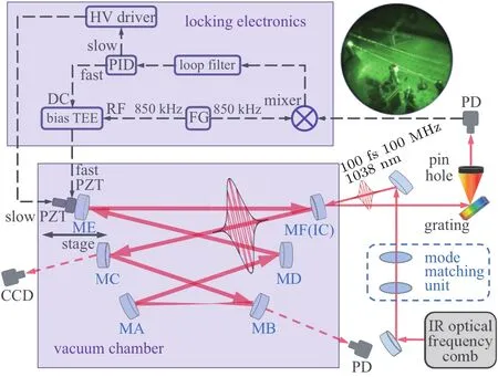
Fig.1.Schematic view of the six-mirror bowtie fsEC setup.The inset at the upper right shows the IR-viewer photograph of the fsEC under air condition.The acronyms in the figure are given by:HV,high voltage;FG,function generator;PZT,piezo transducer;CCD,charge coupled device;PD,photodetector;IC,input coupler;PID,the proportional-integral-derivative circuit;MA(MF),mirror A(mirror F).
A schematic view of our experimental setup is shown in Fig.1.The fsEC is pumped with a high-power Yb-doped fibre optical frequency comb,which provides 100-fs pulses with a repetition rate of 100 MHz and a center wavelength of 1038 nm.This IR comb,with its transverse mode manipulated by a mode-matching unit,is guided into the fsEC.ThefsEC is composed of six high-reflectivity mirrors.Five of them,labeled as MA–ME in Fig.1,have a reflectivity higher than 99.95%.The input coupler,noted as MF(IC),has a reflectivity of 99.2%.The dispersions of all mirrors are less than 20 fs2in the wavelength range of 1010 nm–1065 nm.With this design,the finesse of the cavity is expected to be about 600 and the theoretical buildup is 290.In order to achieve the coherent addition of the IR driving laser,the FSR of the fsEC has to be the same as the repetition rate of the optical frequency comb,i.e.,FSR=c/L=100 MHz.Thus,the length of the cavity is set to be 3 meters.In order to realize a fine adjustment of the cavity length,ME is mounted on a translation stage with piezo transducers(PZT).A feedback loop(the shade region labeled with “locking electronics”)is also used,and the detail will be elaborated in following paragraphs.The entire fsEC is placed in a vacuum chamber in order to avoid the influence of air or dust.The chamber is evacuated with a 250-l/min dry pump(Anest Iwata ISP-250C)and a 250-l/s turbo pump(Pfeiffer HiPace300),and a background pressure as low as 10?4Pa can be achieved.
The intracavity peak intensity of the IR laser can be calculated as:
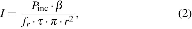
where Pincis the average power of the incident laser,β is the buildup,τ is the pulse duration,r is the beam radius at the focus.To attain a high peak intensity inside the cavity,we intentionally design the cavity to have a beam radius as small as~20μm in the focus region.This is achieved by using two concave mirrors(CM),which have radii of curvature(ROC)of 10 cm(MB)and 15 cm(MA),respectively.With this design,the beam size at the focus as a function of mirror separation between MA and MB is calculated,as shown in Fig.2.A beam radius of~20μm in the focus region can be achieved by setting the mirror separation to be 12.7 cm.Under this condition,an intracavity peak intensity of 8×10¹³W/cm2can be achieved if we assume Pinc=50 W,β=200,fr=100 MHz,τ=100 fs.Thus,noble gases,such as Xe,Kr,Ar,are proper gas targets for intracavity HHG.

Fig.2.Theoretical beam radius at the focus as a function of concave mirror separation calculated by ABCD matrix method.
With the aid of ABCD matrix theory,the beam size of the transverse eigen mode inside the cavity is simulated,as shown by the red line in Fig.3.In order to achieve an efficient coupling between the IR laser and the fsEC,mode-matching outside the cavity has to be optimized.This is achieved by the mode matching unit,as shown in Fig.1.The mode matching unit is composed of two lenses with focus lengths of f1=1000 mm and f2=?500 mm,respectively.They are mounted on translation stages for distance optimization.The separation of them is set to be 40 cm under our experimental condition.The measured beam size after the mode matching is also shown in Fig.3.The evolution trend of the beam size matches the prediction qualitatively.

Fig.3.Simulated and measured beam radii at each position of the fsEC with the separation of the CMs of 12.7 cm.The red curve is the theoretical value while the blue dots are the measured values.The red triangles denote the positions of the six cavity mirrors.
The beam radii in Fig.3 are measured in the beam path and can be considered as the results of a single pass in the fsEC(no enhancement yet).Fine adjustment is necessary because the real beam radii in the fsEC are the results of multiround trips,and they can be affected by displacement of lens positions,misalignment of the laser beam,etc.In the experiment,optimization of the mode matching can be realized by fine adjustment of the positions of the two lenses relative to the IC,while monitoring the resonance mode of the incident laser during the cavity-length scanning process.Figure 4(a)shows the observed transmitted signal before optimization of the mode matching.Clear sign of higher-order mode is observed,as indicated by the arrows in the figure.Figure 4(b)shows the result of transmitted signal after optimization of the mode matching.Signals of higher-order mode are much weaker,and the buildup related to the TEM00mode becomes much higher.
As can be clearly seen in Fig.4(b),there are a series of positions where enhancement can be observed.However,there is only one position where the highest enhancement is reached.The further away from this position,the lower the enhancement factor is.This feature is very different from the case of a CW enhancement cavity,for which the laser can be enhanced to the same extent every time the length of the cavity is changed by a wavelength of the incident laser.For an fsEC,however,the increasing number of modes make the situation more complex.As explained in the previous part,a femtosecond laser is composed of a series of comb lines that are equally spaced by frin the frequency domain.Taking our pump IR laser for example,the number of comb lines is about 106,which means that 106CW lasers have to be enhanced simultaneously,as schematically shown in Fig.5(a).However,it is possible that only a portion of the comb lines will overlap with the cavity modes.As a consequence,a series of side peaks with a reduced buildup is observed,as shown in Fig.5(b).
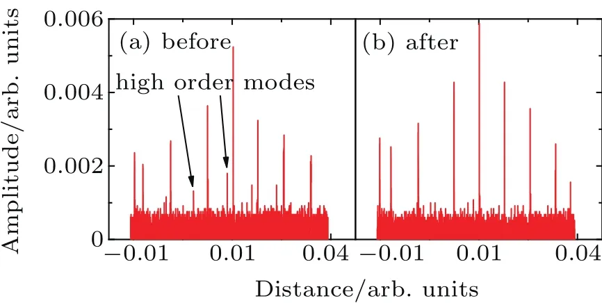
Fig.4.(a)The intensity of transmission while scanning the cavity length before mode-matching optimization.(b)Same as in panel(a)but after mode matching optimization.
Those side peaks in Fig.5(b)can also be understood in the time domain.The reason that the femtosecond pulse can be enhanced is that the reflected pulse is overlapped in time with the following incident pulse.This means not only their shape of envelope but also the inner electric field are completely overlapped.If the length of the fsEC changes by a wavelength of the incident laser,the pulse after travelling one round trip in the cavity will not overlap with the next pulse completely,even though the phase of electric field inside envelope keeps the same.Under this condition,only a portion of each pulse contributes to the coherent addition,giving rise to a reduced buildup.Similarly,if the length of cavity changes by more than one wavelength,the overlapping portion of pulses further reduces,so does the buildup.

Fig.5.(a)Ideal enhancement can be reached when all the laser modes match the resonance modes of the fsEC.(b)Less enhancement appears when some of the laser modes match the resonance modes of the fsEC.(c)The effect of f0on the enhancement.
In order to enhance all the comb lines in the fsEC,as discussed in previous sections,both f0and frhave to be matched with each other precisely.frcan be roughly determined by setting the cavity length to be 3 m.After observing the resonance,a proper frcan be determined according to the position where the center peak in Fig.4(b)is the highest.f0can also be well determined after frand mode matching are properly optimized.In our experiment,the role of f0is clearly demonstrated when we set f0to be,e.g.,20 MHz and 40 MHz,respectively,as shown in Fig.5(c).As we can see,not only the height of the center peak,but also the height of the sidebands,are affected by f0.Thus,by observing this difference,the proper value of f0,i.e.,40 MHz,is determined under our experimental condition.
Through the above steps,the fsEC is optimized to the conditions that the coherent addition of the laser field inside the fsEC is most efficient.To get a stable intracavity power,we also need to lock the length of the cavity.Here the Pound–Drever–Hall(PDH)technique[21,22]is adopted.In our experiment,we have attained the differential signal of the reflected dip by modulating sidebands,as shown in Fig.1.The fastloop PZT(Thorlabs PA4HKW,pasted behind ME)is driven with a modulation signal at 850 kHz by a function generator,which generates two sidebands at 850 kHz on both sides of the repetition frequency.These sidebands are detected by the photodiode after the grating,and then mixed with the modulation source.The mixer would output the differential signal of the reflected dip,i.e.,the PDH error signal,as shown in Fig.6(a).The PDH error signal is processed by the loop filter and the proportional-integral-derivative(PID)circuit.The output is then divided into two channels.One channel is directly sent to the fast-loop PZT,and the other one is amplified by the HV driver and then acts on the slow-loop PZT(Thorlabs AE0505D08F,mounted on the translation stage).In this way,the cavity can be locked for more than one hour.After locking,the intensity of the transmitted laser maintains the maximum of the transmitted peak,as shown in Fig.6(b).
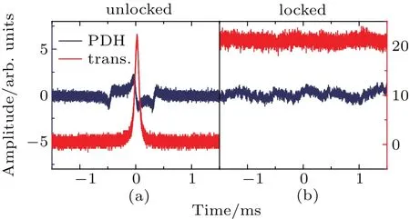
Fig.6.(a)PDH error signal and the intensity of transmission when the length of the cavity is slowly swept.(b)After locking,the intensity of transmission maintains maximum and the PDH error signal becomes a flat line.
After locking the fsEC,we have measured the spectra of the incident laser(about 3 W)and the transmission from the fsEC,and the results are shown in Fig.7.One can find that,by employing low dispersion cavity mirrors,the shapes of the two spectra are very similar to each other,indicating that most of the driving optical frequency comb teeth are enhanced.However,a significant difference near 1035 nm is still noticeable.This difference is mostly likely due to high order dispersion induced in the fsEC.
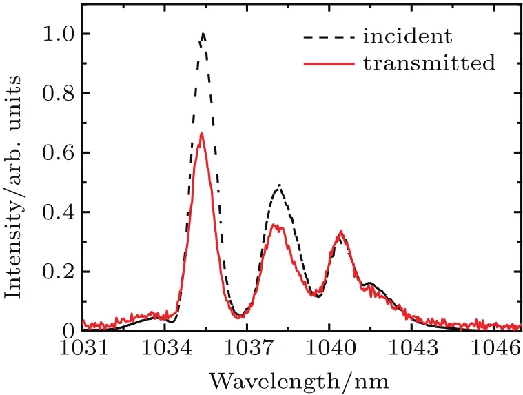
Fig.7.The spectra of the incident and transmitted signal with incident power of~3 W.
According to the design of our fsEC,the femtosecond pulses have to travel in the fsEC for more than a few hundred times.This feature makes the dispersion of the cavity mirrors important.Actually,the bandwidth and buildup of the fsEC have been proved to be affected by dispersion.[9,23,24]The total phase shift φd(ω)induced by dispersive elements is expressed as the sum of different orders of dispersion with Taylor expansion:
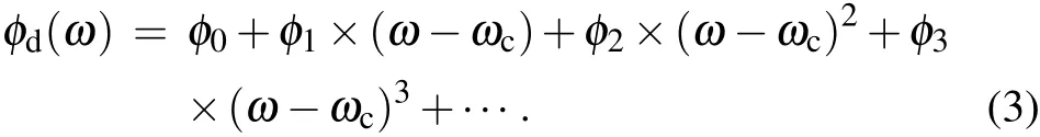
Here,ωcis the center frequency with zero dispersion.Each dispersion order affects the intracavity laser pulse differently.φ0will cause a phase shift of the electric field but will not affect the position of the envelope.φ1will cause a translation of envelope,but the inner phase will not change.φ2will broaden the pulse symmetrically in time.φ3and higher order terms will distort the pulse in a more complex way.φ0and φ1can be compensated by changing the repetition rate and the CEO frequency of the incident laser,but the higher order terms cannot.Suppose the phase shift due toφ0and φ1are well compensated,the buildup can be expressed as:

where ticand ricare the transmissivity and the reflectivity of the IC,respectively;rcavis the total reflectivity of other cavity mirrors;m is an integer;and φ0d= φ2×(ω ?ωc)2+φ3×(ω ?ωc)3+···Thus,the further away from the center frequency with zero dispersion,the less it can be enhanced.This is in line with our observation,since the center wavelength with zero dispersion is 1040 nm for our cavity mirrors.
Finally,we have increased the incident power and measured the corresponding intracavity power,as shown in Fig.8.When an incident power has reached 27 W,a transmitted power of 51.4 mW has been obtained.The average transmissivity of the high-reflectivity mirrors was calibrated to be 8.46×10?6.During the calibration process, five random mirrors were chosen and the scattering light was eliminated by a 20-cm-long tube that mounted between the mirror and the power meter.Thus,an intracavity average power of 6.08 kW and a buildup of 225 have been achieved.Suppose that the pulse duration inside the enhancement cavity is 100 fs and the beam radius at the focus is~20μm,an intensity as high as 4.8×10¹³W/cm2has been achieved.
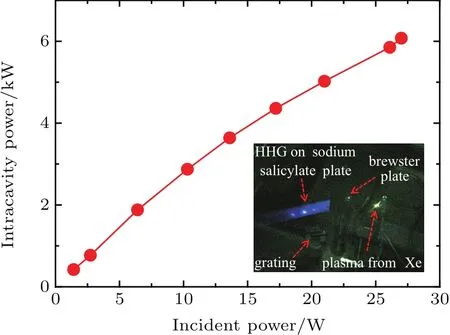
Fig.8.The intracavity power as a function of incident power.The inset shows the photograph of the focus region of the fsEC.Xe gas is injected to the focus region using a gas nozzle.A sapphire plate is placed behind the focus at Brewster’s angle for the fundamental laser.The out-coupled HHG is diffracted by a grating,and detected by a sodium salicylate plate.
In order to verify the peak intensity we have achieved,Xe gas is injected to the focus region using a gas nozzle with a 150-μm inner diameter.The typical backing pressure is about 1 atm,with<1 Pa of background pressure for the vacuum chamber.To couple the copropagating HHG light out of the cavity,a 350-μm-thick sapphire plate is placed behind the focus at Brewster’s angle for the fundamental laser.The outcoupled HHG is diffracted by a grating,and detected by a sodium salicylate plate.Bright fluorescence on the sodium salicylate plate was observed,as shown in the inset of Fig.8,indicating that HHG in the fsEC was generated.With a band pass filter,the third harmonic was selected from the leakage of the cavity mirror and measured to be 8.9μW.After considering the reflectivity and transmission of all optics,the power of the generated third harmonics was estimated to be 260.4μW inside the enhancement cavity.Suppose the power in the plateau region is 2 orders of magnitude lower than the third harmonic,[25]a fewμW power is believed to be generated in the XUV region.
3.Conclusion
In conclusion,we have successfully built a six-mirror bowtie fsEC that works jointly with our pump IR laser.The measured transmitted spectra indicate that high order dispersion plays a non-negligible role in the enhancement process.After optimization of the cavity-length and the mode-matching of the fsEC,the cavity can be locked to maintain the maximum intracavity power through the PDH technique.With a pump power of 27 W,we have achieved an intracavity power of 6.08 kW and the corresponding buildup is 225.After introducing Xe to the focus region,HHG has been observed and coupled out of the fsEC,paving the way for the realization of an XUV comb in the near future.This fsEC also enables intra-cavity high harmonic generation and related studies,e.g.,mixing gas experiments,[7,26]multi-color experiments,[27]etc.
[1]Jones R J,Moll K D,Thorpe M J and Ye J 2005 Phys.Rev.Lett.94 193201
[2]Gohle C,Udem T,Herrmann M,Rauschenberger J,Holzwarth R,Schuessler H A,Krausz F and Hansch T W 2005 Nature 436 234
[3]Cingoz A,Yost D C,Allison T K,Ruehl A,Fermann M E,Hartl I and Ye J 2012 Nature 482 68
[4]Pupeza I,Holzberger S,Eidam T,Carstens H,Esser D,Weitenberg J,Russbuldt P,Rauschenberger J,Limpert J,Udem T,Tunnermann A,Hansch T W,Apolonski A,Krausz F and Fill E 2013 Nat.Photon.7 608
[5]Benko C,Allison T K,Cingoz A,Hua L,Labaye F,Yost D C and Ye J 2014 Nat.Photon.8 530
[6]Ozawa A and Kobayashi Y 2013 Phys.Rev.A 87 022507
[7]Porat G,Heyl C M,Schoun S B,Benko C,Dorre N,Corwin K L and Ye J 2018 Nat.Photon.12 387
[8]Hogner M,Tosa V and Pupeza I 2017 New J.Phys.19 033040
[9]Lilienfein N,Hofer C,Holzberger S,Matzer C,Zimmermann P,Trubetskov M,Pervak V and Pupeza I 2017 Opt.Lett.42 271
[10]Winkler G,Fellinger J,Seres J,Seres E and Schumm T 2016 Opt.Express 24 5253
[11]Ozawa A,Zhao Z,Kuwata-Gonokami M and Kobayashi Y,et al.2015 Opt.Express 23 15107
[12]Carstens H,Lilienfein N,Holzberger S,Jocher C,Eidam T,Limpert J,Tunnermann A,Weitenberg J,Yost D C,Alghamdi A,Alahmed Z,Azzeer A,Apolonski A,Fill E,Krausz F and Pupeza I 2014 Opt.Lett.39 2595
[13]Eyler E E,Chieda D E,Stowe M C,Thorpe M J,Schibli T R and Ye J 2008 Eur.Phys.J.D 48 43
[14]Bergeson S D,Balakrishnan A,Baldwin K G H,Lucatorto T B,Marangos J P,McIlrath T J,O’Brian T R,Rolston S L,Sansonetti C J,Wen J,Westbrook N,Cheng C H and Eyler E E 1998 Phys.Rev.Lett.80 3475
[15]Haas M,Jentschura U D,Keitel C H,Kolachevsky N,Herrmann M,Fendel P,Fischer M,Udem T,Holzwarth R,Hansch T W,Scully M O and Agarwal G S 2006 Phys.Rev.A 73 052501
[16]Herrmann M,Haas M,Jentschura U D,Kottmann F,Leibfried D,Saathoff G,Gohle C,Ozawa A,Batteiger V,Knunz S,Kolachevsky N,Schussler H A,Hansch T W and Udem T 2009 Phys.Rev.A 79 052505
[17]Prior M H and Shugart H A 1971 Phys.Rev.Lett.27 902
[18]Semczuk M 2009 “An ion trap for laser spectroscopy on lithium ions”,MS Thesis(Warsaw:University of Warsaw)
[19]Ferray M,Lhuillier A,Li X F,Lompre L A,Mainfray G and Manus C 1988 J.Phys.B:At.Mol.Opt.Phys.21 L31
[20]Cundiff S T 2002 J.Phys.D:Appl.Phys.35 R43
[21]Black E D 2001 Am.J.Phys.69 79
[22]Zhang J W,Han H N,Hou L,Zhang L,Yu Z J,Li D H and Wei Z Y 2016 Chin.Phys.B 25 014205
[23]Moll K D,Jones R J and Ye J 2005 Opt.Express 13 1672
[24]Han H N,Zhang J W,Zhang Q,Zhang L and Wei Z Y 2012 Acta Phys.Sin.61 164206(in Chinese)
[25]Ozawa A,Rauschenberger J,Gohle C,Herrmann M,Walker D R,Pervak V,Fernandez A,Graf R,Apolonski A,Holzwarth R,Krausz F,Hansch T W and Udem T 2008 Phys.Rev.Lett.100 253901
[26]Jin C,Zhou X X and Zhao S F 2010 Chin.Phys.Lett.27 033301
[27]Zhang H D,Guo J,Shi Y,Du H,Liu H F,Huang X R,Liu X S and Jing J 2017 Chin.Phys.Lett.34 014206

- Chinese Physics B的其它文章
- Effect of carrier mobility on performance of perovskite solar cells?
- Plasma electrolytic liquefaction of sawdust?
- Insight into band alignment of Zn(O,S)/CZTSe solar cell by simulation?
- Effect of terahertz pulse on gene expression in human eye cells?
- Ultraviolet photodetectors based on wide bandgap oxide semiconductor films?
- A primary model of decoherence in neuronal microtubules based on the interaction Hamiltonian between microtubules and plasmon in the neurons