Extra-large Undersea Shield Tunnel in Composite Ground:Maliuzhou Traffic Tunnel in Zhuhai
2018-04-19 06:49:52ZHUYanfeiLILeiWUHuiming
隧道建設(中英文) 2018年3期
ZHU Yanfei, LI Lei, WU Huiming
(Shanghai Tunnel Engineering Co., Ltd., Shanghai 200232, China)
1 Project objective
Extra-large shield tunnels have become the best choice for urban transportation tunnels due to the advantage of taking the best use of underground space. Hengqin Island in Zhuhai is a demonstration area to explore a new cooperation mode among Guangzhou, Hong Kong and Macao, which is also an important pivot of the 21st Century Maritime Silk Road. Thus, it takes an important role in serving Hong Kong and Macao and driving the economic development of the Pearl River Delta. However, as typhoons are frequent in Zhuhai, Hengqin Island will be isolated to the mainland when bridges are obstructed in typhoon seasons. Therefore, the bridges cannot satisfy the traffic demand to the island. The inconvenient transportation has a neglect influence on production and live of people on the island, which also affects the long term development of Hengqin Island.
Apart from the two existed bridges, Maliuzhou Traffic Tunnel in Zhuhai is the third major link of Hengqin Island to the mainland, which will put an end to the "losing connection" problem due to obstructing the bridges in typhoon seasons. This linkage is able to promote Zhuhai tourism exploitation and the long term development of the city, and also increase the security of people′s lives. Meanwhile, the construction of the Maliuzhou Traffic Tunnel has conquered the challenges in designing and building of the extra-large shield tunnel in composite ground and undersea circumstances. The designing methods and constructing approaches used in this project will provide theoretical supports and technical guarantees to similar projects.
2 Overview of the project
Maliuzhou Traffic Tunnel is a twin-tube, single-floor, 6-lane dual-carriageway tunnel, which is constructed by a Herrenknecht slurry balanced shield with a diameter of 14.93 m. The shield launches at the working shaft on the south coast. Then after finishing the west line tunnel, the boring machine made a U-turn in the working shaft on the north coast to go on boring the east line tunnel. The plan layout and logitudinal profile of Maliuzhou Traffic Tunnel is shown in Fig. 1. The tunnel has an outer diameter of 14.5 m, an inner diameter of 13.3 m. The segment ring has a width of 2.0 m, which is made of the concrete with the strength in Grade C55 and the impermeability in Grade P12. The segments are generally wedge shaped and assembled with staggered joints. The west tube and the east tube have the lengths of 1 082 m and 1 081 m respectively; meanwhile, the lateral clearance between the two tubes is 6.5-15 m. The tunnel has the minimum alignment radius of 1 170 m, and the burial depth of 8.5-15.5 m.
The geological condition of the project is composite with soft soil on the top and hard rock on the bottom. It is a typical ground in the south of China. The TBM tunnel crosses the Maliuzhou Channel through the composite ground which is consisted of ②2clay, ②3medium coarse sand with clay, ②4silty clay, ④medium coarse sand, and ⑤gravelly clayed soil. In addition, in some regions, the ground contains shallow-buried high strength rock including ⑥fully, strongly and moderately weathered granite. Meanwhile, numerous obstacles are observed in tunneling working face, such as plastic drainage panels, rip-rap stones and spherical weathered rock (boulder). The maximum uni-axial compressive strength of the bedrock reaches 80.4 MPa, with the average value of 43.8 MPa. The uni-axial compressive strengths of rip-rap stones are generally larger than 60 MPa, with the maximum value of 120 MPa. Maliuzhou Channel is about 600 m wide, of which the water level difference is about 1.5 m due to sea tides. In particular, the difference even reaches 3 m in rainstorm seasons.
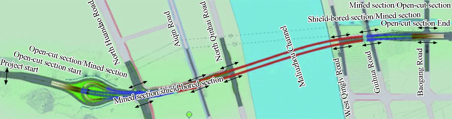
(a) Plan layout
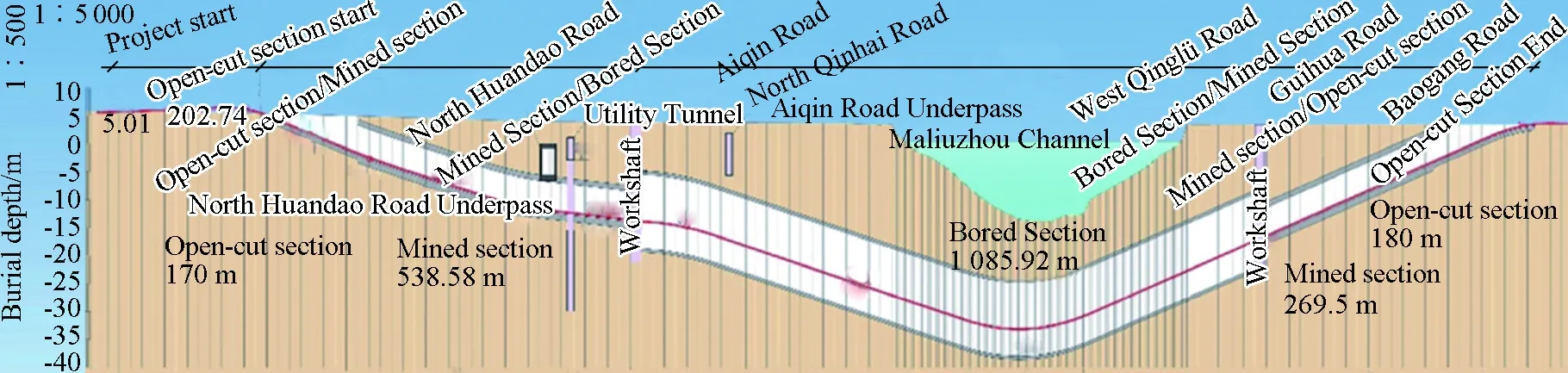
(b) Longitudinal profile
3 Engineering challenges and construction strategies
3.1 Engineering challenges
As the first extra-large undersea shield tunnel in composite ground in China, Maliuzhou Traffic Tunnel has the following challenges:
(1)Composite ground with soft soil on the top and hard rock on the bottom. In some sections of the tunnel alignment, the excavating faces were located in composite ground with soft clay, medium coarse sand, gravelly clay and granite. The cutting tools must be capable to cut both soft and hard stratum. Moreover, the controlling parameters of the tunneling must ensure smooth driving of the shield, and avoid the consequences that of the shield gets jammed or clay gets clogging on cutterhead.
(2)Mumerous obstacles along the tunnel alignment. Along the axis of the tunnel alignment, there used to be a municipal road. The vacuum pre-loading drainage consolidation method and rip-rap compaction method were used to strengthen the foundation of the road. Therefore, lots of plastic drainage panels and riprap stones left along tunneling route at the land area. Meanwhile, there were also lots of spherical weathered rocks (boulders) along the whole alignment, which brought unprecedented challenges to the shield tunneling.
(3)New slurry mixture design in undersea circumstances. Since Maliuzhou Channel is located at the Pearl River estuary, with the contents of chloride, magnesium ion and calcium ion are higher than those in normal water. These contents will cause the deterioration of the slurry and decrease the quality of the slurry film, which endangers the stability of the excavating face. Thus, it was very critical to design a new slurry mixture.
(4)Extra-large shield tunneling. As the first extra-large shield tunnel reaching to 14 m in South China, which can present difficulties such as shield launching and receiveing, tunneling under shallow overburden, crossing under embankment and controlling the stability of the composite ground, increased the safety risk of shield tunneling. Besides, the strong rocks in regional area aggravated the wear of cutterhead and cutting tools. It was very risky to replace cutting tools under large pressure underwater.
3.2 Construction strategies
In order to deal with the engineering challenges, the construction team had developed several methods such as making elaborate design of the tunnel structure in the composite ground, targeted design of the shield, excavation pretreatment, regulating the slurry performance undersea, and improving the ground adaptability of cutting tools.
3.2.1 Elaborate design of the tunnel structure in composite ground
The shield tunnel structure was designed by using an elaborate method. The method was based on the Terzaghi Load Formula, which was futher modified by theoretical analyses to determine the transverse loadings for the extra-large shield tunnel in the ground with undulating bedrock. In addition, according to the elastic strain theory of thick-walled cylinder, the influence of the grouting layer on the ground resistance coefficient was considered to develop the calculating model for the segment with the compositive resistance from grouting layer and ground. Then, thus the behavior of the tunnel structure could be more accurately analyzed. According to the in-situ recorded data of water pressure, earth pressure and stress of the reinforced steel, the practice internal forces of the segment structure could be calculated. At last, according to the campasions between theoretic results and the recorded results, it was indicated that the results based on the elaborate design method were close to the measured results. The comparison of the internal forces of the tunnel segments is shown in Fig. 2.
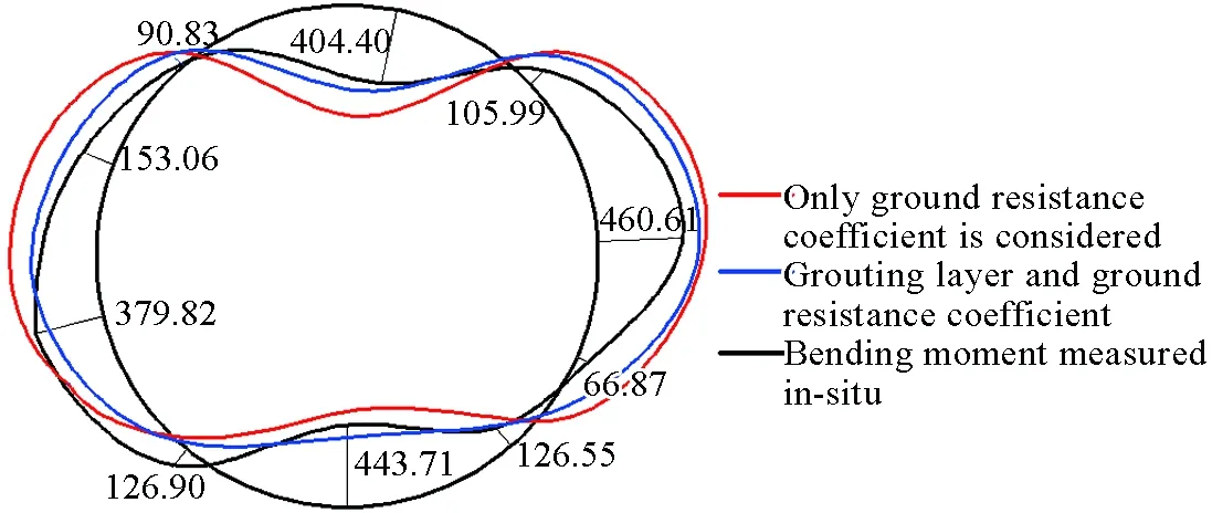
(a) Bending moment (unit: kN·m) (b) Axial force (unit: kN)
Fig. 2 Comparison of internal forces of tunnel segments
3.2.2 Targeted design of shield
The cutterhead of the shield had a diameter of 14.93 m and an opening ratio of 57%. The cutter is composed of 127 disc cutters, 182 scrapers, 43 pre-cutting cutters, 16 peripheral scrapers, 8 diameter maintaining cutters, 1 copy cutter, 5 tool wear detection devices and 1 device for detecting the abrasion of cutterhead steel structure. Meanwhile, the shield was equipped with a SSP advance detection device to collect and evaluate the data of the front ground conditions continuously during shield tunneling. Also, it was able to forecast the obstacles with the diameter larger than 800 mm in the scope of 40 m ahead of the cutterhead. The layout of the cutting tools is shown in Fig. 3 and the sketch of SSP advanced detection is shown in Fig. 4.
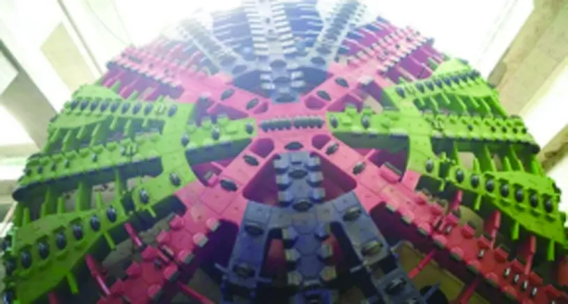
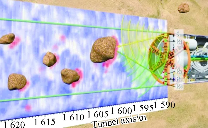
Fig. 3 Layout of cutting tools Fig. 4 Sketch SSP advanced detection
High performance jaw crusher (Fig. 5) could crush the stones entering into the slurry chamber and prevent them from accumulating at the mud discharge pipe inlet, thus to ensure smooth transportation of the muck. The crushing efficiency of the crusher should in concert with the driving speed of the shield. To prevent large gravels from clogging the mud discharging pipes, there was a gravel trapper (Fig. 6) in front of the muck pump to collect large gravels entered from the inlet.
3.2.3 "Combo" of excavation pretreatment
When TBM drove through the composite ground, cutterhead and cutting tools would be abrased rapidly due to stiff bedrock and boulders. When this is the case, frequent interventions were needed to replace the cutting tools. If the shield got jammed, the cutterhead was damaged or the intervention condition was not satisfied, the construction efficiency would be greatly affected. Therefore, the pre-excavation reinforcement measures were taken to avoid these risks and to ensure smooth tunneling.
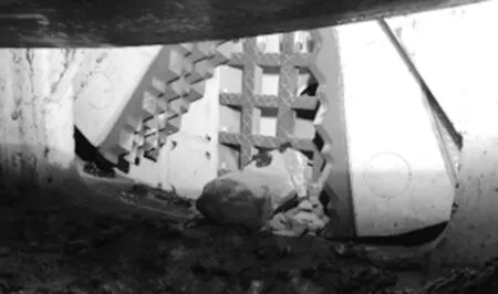
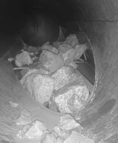
Fig. 5 Jaw crusher Fig. 6 Gravel trapper
3.2.3.1 Elaborate geological survey
Geophysical methods that frequently used on land physical detection, such as shear wave reflection method and cross-hole electrical resistivity tomography, were not applicable in the area of the Maliuzhou Channel. In order to determine distribution of bedrocks and boulders in the undersea section, the construction team used the seismic scattering profile (SSP) method to survey geological conditions from above water (as shown in Figs. 7 and 8). Geological profiles and 3D wave velocity database of the surveyed area were developed by using the SSP method. It was discovered that there were 25 boulders/bedrocks distributed along the TBM driving route, which were classified according to their sizes and strengths. There were 9 boulders/bedrocks with the diameter larger than 3 m and hardness over Grade 2 (i.e. in which wave velocity exceeded 2 500 m/s). According to the survey results, the basic distributions of boulders and bedrocks within the undersea section were determined, which provided accurate position information for the following drilling-and-blasting processes.
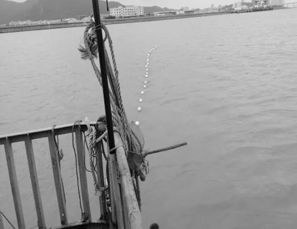
Fig. 7 Wave detection cables Fig. 8 Seismic data collection
3.2.3.2 Underwater detonation
According to the geophysical results, the bedrocks intruded in the tunneling face under the channel were all dynamited into pieces. Blasting holes were drilled by a drilling machine that fixed on the work vessel. A steel casing pipe was hammered into the stone in advance; then, a PVC pipe was pressed in the steel casing pipe to support the hole after the hole was excavated. Millisecond nonel detonators were used in the blasting holes, and instantaneous electric detonators were used to trigger the explosion. The standard diameter of the emulsion explosive (Fig. 9) was 60 mm. The blasting hole spacing was 0.8-1.2 m. In order to ensure the quality of blasting, the depth of the blasting hole below the tunnel bottom was no less than 1.5 m. The underwater blasting is shown in Fig. 10.
3.2.3.3 Blasting holes sealing
Once a complete passage is formed in the ground through the blasting holes, slurry gushing will happen during the shield tunneling. Therefore, the blasting holes before blasting and the passages formed after blasting must be sealed. For the blasting holes drilled by machines, small explosive packs were installed in the ground above the tunnel. The amount of explosive was controlled to be just enough to break the PVC pipes, so that the PVC pipes would not form a passage connecting the riverbed and the tunneling face. The passage formed by pulling out the steel casing pipes were sealed with pouring expansive soil balls and stones when pulling out the pipes. The blasting hole passages formed after blasting in the under-channel sections were sealed by reinforcing the riverbed with high pressure rotary grouting. The rotary spraying rigs were carried by modified vessels. The blasting holes passage sealing under channel is shown in Fig. 12.
Fig. 9 Emulsion explosive and detonators fixing Fig. 10 Underwater blasting

Fig. 11 Illustration of blasting holes sealing Fig. 12 Blasting hole passage sealing under channel
3.2.4 Regulating and controlling the Slurry Undersea
In considering the characteristics of the undersea environment, 48 groups of in-door slurry tests were designed with different slurry materials, mixture proportions and solvents. Common bentonite and seawater bentonite, with 3 additives including sodium alginate, kelp powder and seawater specialized slurry agent, were used as main components. Fresh water and seawater were used as solvents. The slurry test is shown in Fig. 13.
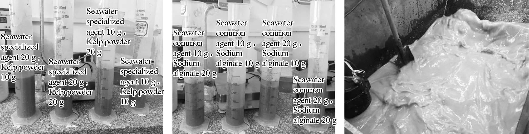
(a) Isolation of kelp powder slurry (b) Isolation of sodium alginate slurry(c) Slurry preparation
Fig. 13 Slurry test
According to the slurry tests and the experience in the construction of Maliuzhou Traffic Tunnel, driving performance data of different test sections corresponding to 3 additives, such as kelp powder, sodium alginate and seawater specialized slurry agent, were compared. It was indicated that the seawater specialized slurry agent could significantly improve the boring speed of the shield (about 1.5 times), and reduce the cutterhead torque (about 50%) and the total thrust (about 15%). Then the stability of the excavating face was reached; at the same time, the tunneling speed got stabilized and mucking got more efficient. Furthermore, the deterioration of the slurry in undersea environment was prevented.
3.2.5 Improvement of ground adaptability of shield cutting tools
In order to deal with the silt ground and the plastic drainage panels everywhere in the land section, before shield launching, 46 of 127 disc cutters were replaced by shell bits, which were cooperated with the pre-cutting cutters to excavate. In order to ensure the efficiency of the excavation in the rock sections under the channel, during the time that the shield was under examination in the south embankment reinforced area, 23 of the 46 shell bits in the central area of cutterhead were replaced by disc cutters, while the rest of the shell bits kept unchanged. The pretreatment measures ensured smooth boring in the west line rock area, and avoided unpredictable accidents such as shield jamming and riverbed collapsing. When the shield was crossing the first rock section, the driving speed was controlled at about 10 mm/min; after the third rock section, the driving speed increased to about 20 mm/min. In that case, torque and thrust were still relatively stable. The length of most of the muck transported is within 10 cm, and few reaches 20 cm, as shown in Fig. 14.
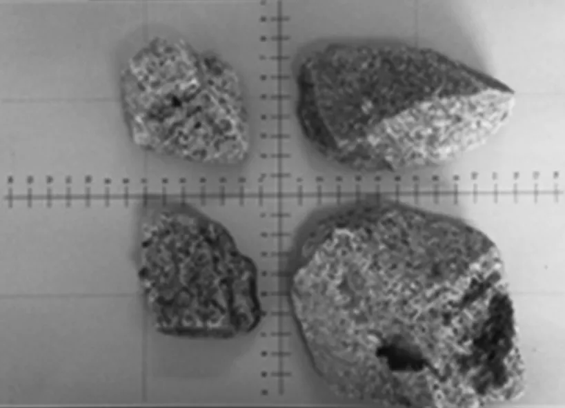
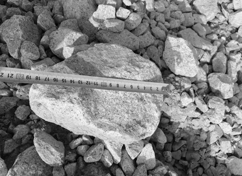
(a) Rock at Ring 311 (b) Rock size measuring
Fig. 14 Muck transported in the west line rock sections
After completing the west line, the examination showed that 40 of the 104 disc cutters were unevenly worn. The damages were distributed in 3 m range of the cutterhead periphery, and the largest uneven wear amount was about 40 mm. The cutting rings of 7 disc cutters dropped off, which were distributed at the junction of the front surface and the surface of the cutterhead. Besides, all scrapers were severely worn. According to the driving parameters and the abrasion indices of the cutting tools in the west line, the cutting tool configurations were improved before shield launching in the east line: (1) All cutting tools in 3 m range of the cutterhead periphery were switched to 18 inch heavy disc tools; (2) Scrapers were switched to better ones with inlaid alloy; (3) 33 shell bits were added on the front surface of the shield at 10 mm lower than the 17 inch disc cutters, of which with the inlaid alloy was the same as shell bits in the central area, to assist the disc cutters.
The driving speed of the modified shield was controlled to be 20 mm/min to cross the first rock section of the east line, and muck transportation was efficient. In the second rock section of the east line, rocks that intruded in the tunneling face were as high as 5.8 m, and were more intact and of higher strength. In order to check the wear condition of the cutting tools, and ensure that the shield could cross the second rock section of the east line smoothly, an intervention chamber was constructed in the improved ground between the 210th ring and the 219th ring. The intervention, including inspection in the excavation chamber and cutting tools changing, which lasted 16 days. During that period, 14 disc cutters, 10 sets of peripheral scrapers, and 4 front scrapers were changed. With the driving speed of 6 mm/min, the torque after intervention was significantly reduced. The intervention under the channel ensured that the shield passed the second section smoothly and continued moving forward until breakthrough.
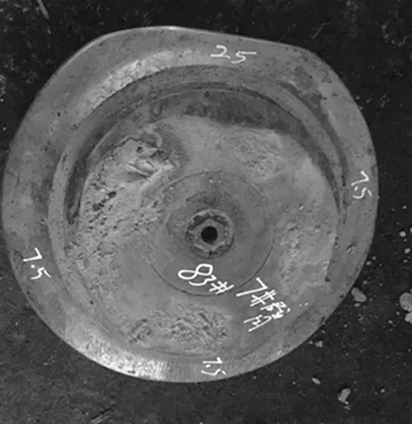
(c) Arm #15 Disc cutter #83
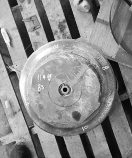
(b) Arm #11 Disc cutter #83
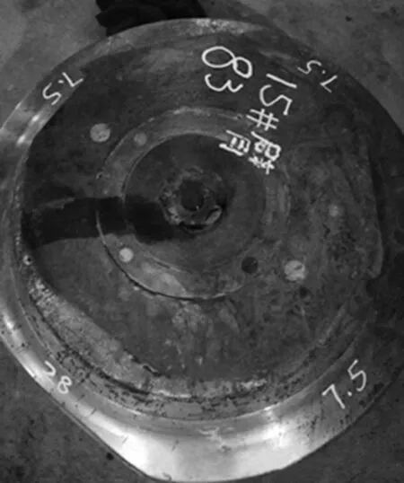
(a) Arm #7 Dic cutter #83
Fig. 15 Under-channel inspection for the condition of cutter tools in the excavation chamber
4 Main technical innovations
Regarding to undersea environment and composite ground condition of "soft soil above-hard rock below" of the project, transversal and longitudinal computation models of the extra-large shield tunnel in composite ground were developed according to the behavior of segments. In addition, a series of measures were developed for the shield design in composite ground and excavation pretreatment. A series of control techniques were developed for the slurry treatment undersea and the composite ground during shield tunneling. These techniques ensured the success of the tunnel excavation, and promoted the technical development to extra-large shield tunnels.
5 Project schedule
The TBM started boring the west line tunnel on January 22th, 2016, and completed on December 7th, 2016. After U-turning, the TBM started boring the east line on April 14th, 2017, and completed on November 13th, 2017.
6 Achievements and honour
(1)Operation standards for extra-large undersea shield tunneling in composite ground.
(2)First prize of honorable mention of 2017 National Municipal Enginging Construction Quality Control.
(3)Grade AA Security & Civilization Standardized Construction Plant of Guangdong, 2016.
7 Project partieipants
Owner: Zhuhai Dahengqin Stock Co., Ltd.
Designer: Shanghai Urban Construction Design & Research Institute.
Contractor: Shanghai Tunnel Engineering Co., Ltd.
Supervisor: Guangzhou Municipal Engineering Consultant Co., Ltd.

- 隧道建設(中英文)的其它文章
- Statistics of Railway Tunnels in China as of 2017
- 高速鐵路隧道支護參數的計算研究
- 2018年世界隧道大會暨國際隧協(ITA)第44屆年會將在迪拜舉辦
- Chinese Longest Sea-crossing Metro Tunnel:Wuyuan Bay Station-Liuwudian Station Section of Xiamen Metro Line #3
- Construction Technologies for Tunnels in Special and Complicated Geology of Lanzhou-Chongqing Railway
- TBM滾刀布置方案對比分析與評價