Numerical simulation of Gurney flap on SFYT15thick airfoil
2017-01-06 08:47:00XiHeJinjunWngMuqingYngDongliChoYnPeiqingLiu
Xi He,Jinjun Wng,?,Muqing Yng,Dongli M,Cho Yn,Peiqing Liu
aFluid Mechanics Key Laboratory of Education Ministry,Beijing University of Aeronautics and Astronautics,Beijing 100191,China
bInstitute of Aircraft Design,Beijing University of Aeronautics and Astronautics,Beijing 100191,China
Numerical simulation of Gurney flap on SFYT15thick airfoil
Xi Hea,Jinjun Wanga,?,Muqing Yangb,Dongli Mab,Chao Yana,Peiqing Liua
aFluid Mechanics Key Laboratory of Education Ministry,Beijing University of Aeronautics and Astronautics,Beijing 100191,China
bInstitute of Aircraft Design,Beijing University of Aeronautics and Astronautics,Beijing 100191,China
H I G H L I G H T S
·Gurney flap can improve aerodynamic performance of SFYT15thick airfoil.
·The mechanism for Gurney flap lift-enhancement is revealed.
·Gurney flap can reduce the wall friction drag at a certain angle of attack.
·Gurney flap can largely increase the pressure drag of the flow around the airfoil.
A R T I C L E I N F O
Article history:
沒想到這個蟲族還挺愛美的,安潔西嘆息著,跳上最后一輛貨車。四輛貨車排成一行前進(jìn),雷狼和亞虎等人跟著頭車,雨馳和安潔西他們則在最后壓陣。
Received 29 June 2016
Received in revised form
3 September 2016
Accepted 8 September 2016
Available online 2 October 2016
Lift enhancement
Airfoil
Gurney flap
A two-dimensional steady Reynolds-averaged Navier–Stokes(RANS)equation was solved to investigate the effects of a Gurney flap on SFYT15thick airfoil aerodynamic performance.This airfoil was designed for flight vehicle operating at 20 km altitude with freestream velocity of 25 m/s.The chord length(C)is 5 m and the Reynolds number based on chord length is Re=7.76×10⁵.Gurney flaps with the heights rangingfrom0.25%C to3%C wereinvestigated.Theshearstresstransport(SST)k-ωturbulencemodelwas used to simulate the flow structure around the airfoil.It is showed that Gurney flap can enhance not only the prestall lift but also lift-to-drag ratio in a certain range of angles of attack.Specially,at cruise angle of attack(α=3°),Gurney flap with 0.5%C height can increase lift-to-drag ratio by 2.7%,and lift coefficient by 12.9%,respectively.Furthermore,the surface pressure distribution,streamlines and trailing-edge flow structure around the airfoil are illustrated,which are helpful to understand the mechanisms of Gurney flaponairfoilaerodynamicperformance.Moreover,itisfoundthattheincreaseofairfoildragwithGurney flap can be attributed to the increase of pressure drag between the windward and the leeward sides of Gurney flap itself.
?2016 The Author(s).Published by Elsevier Ltd on behalf of The Chinese Society of Theoretical and Applied Mechanics.This is an open access article under the CC BY-NC-ND license(http:// creativecommons.org/licenses/by-nc-nd/4.0/).
Gurney flap(GF)is a small flat tab mounted perpendicular to the pressure surface of the airfoil in the vicinity of the trailing edge,which can effectively increase airfoil lift and aerodynamic performance.Because of the significant effect of GF on airfoil aerodynamic performance,a lot of researches were conducted in recent 20 years.
Initial research of GF lift enhancement was conducted by Liebeck[1].Then,numerous studies showed that GF is a simple and efficient aircraft high-lift device[2–9].Wang et al.[10]in the review paper showed that GF can increase the lift coefficient of airfoils,wings,and aircraft both at subsonic and transonic speeds. The use of GF is especially useful during takeoff and landing of aircraft.For optimum aerodynamic performance,the GF should be mounted at the trailing edge perpendicular to the chord line of the airfoil or root chord line of the wing,where its height must be less than the local boundary layer thickness.In addition,they alsoanalyzedandsummarizedlift-enhancementmechanismofGF. Now,GF is widely used to improve the airfoil lift-to-drag ratio, stall control,flutter control,and other aspects.The installation form of GF has transformed from conventional fixed type to active variable type.Amini et al.[11]pointed out that though GF can enhance lift,it increases drag simultaneously.Their numerical simulationusedtheadjointshapeoptimizationprocesstodecrease unfavorable effects on the drag coefficient,which can strongly improve the aerodynamic performance of airfoils with GF by maintaining the lift coefficient and reducing the drag coefficient. Chandrasekhara[12]used a variable droop leading edge(VDLE) airfoil to control compressible dynamic stall,but the price was a10%loss of lift.GF was used for recovering this loss,and the airfoil with GF height of 1%chord length(C)was an optimal choice.Hak-Tae et al.[13]and Stefan and Ilan[14]used miniature trailing edge effectors(MiTEs)which are small movable control surfaces similar to GF.The effectors were mounted at or near the trailing edge to provide high bandwidth and robust control.They illustrated that the MiTEs can inhibit the occurrence of flutter from the perspective of numerical analysis and experiments.Yen et al.[15] mounted micro-electro-mechanical(MEM)translational tabs near the trailing edge of Newman airfoil.The tab is equivalent to a variable GF and able to control the wing load.Through numerical simulation and wind tunnel experiments,they pointed out that this active GF can replace bulky ailerons in the future,so it will reduce the structural weight,complexity and costs.
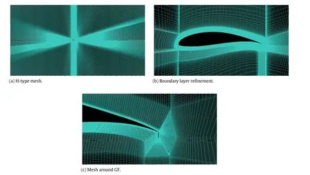
Fig.1.Grid system.
To meet the high altitude,low energy consumption,long flight time,highload,andotherrequirementsofnearspaceflightvehicle, the SFYT15thick airfoil was designed.The purpose of this paper is to install GF on this specially designed airfoil,and analyze its ability to improve the aerodynamic characteristics of the airfoil, thus improving the aerodynamic performance of near space flight vehicle.
The governing equations are the Reynolds-averaged Navier–Stokes(RANS)equations.Fortwo-dimensionalsteadyincompressible flow,the conservation of mass and momentum equations can be written as:

Allthe numericalsimulations wereperformedwith theFLUENT commercial computational fluid dynamics(CFD)software,in which the solution methods were set to solve the RANS equations. The governing equations have a precision of second-order,and pressure–velocity coupling adopts the semi-implicit method for pressure-linked equations consistent(SIMPLEC)algorithm.The pressure term,the momentum term,the turbulent kinetic energy term,and the specific dissipation term are all discretized using the second-order upwind scheme.
The turbulence model adopted in this study is the shear stress transport(SST)k-ωtwo-equation turbulence model proposed by Menter[16].The core idea of this model is to use the robustness ofk-ωmodel to capture the flow of viscous sublayer and to usek-?model in the mainstream area to avoid the disadvantage ofk-ωturbulence model which performs too sensitive in entrance turbulence parameters.SSTk-ωmodel combines the advantages of the standardk-ωmodel and the standardk-?model by mixing functions.Therefore,SSTk-ω model has higher accuracy and reliability in a wide range of flow fields.
In the previous researches of Yu et al.[17]and Zhang et al.[18], thesimulationresultssolvedbySpalart–Allmaras(S–A)turbulence model are in good agreement with experimental data.Moreover, Menter[16]and Rogers et al.[19]found out that for most part of the high-lift problems,the predictions of the S–A and SSTk-ω models are similar.However,it was proposed that SSTk-ωmodel is superior in accurately predicting pressure-induced separation. Therefore,theSSTk-ωmodelcanbemoresuitableinpresentstudy than the S–A model,whose accuracy was verified by Yu et al.[20] and Zhang et al.[21].
At the altitude of 20 km in present study,C=5 m,freestream velocityV=25m/s,ρ=8.8×10-2kg/m3,andμ=1.418×10-5 Pa·s,which result inRe=7.76×10⁵.The H-type mesh generated by elliptical method in ICEM CFD is more suitable,and its accuracy was verified by Ma et al.[22].The computational grid,shown in Fig.1,constitutes 320 grid points on the airfoil surface.The respective distance of the inlet and outlet boundaries away from the leading edge is 20Cand 30C,respectively.The top and bottom boundaries are both 16Caway from the chord.The total grid number is 1.2× 10⁵.In order to capture the boundary layer preciously,thegridmusthaveay+approximatetoone.y+isanondimensional distance which indicates the degree of grid fineness in near-wall region.In the present simulation,the first grid node above the surface is 1.5×10⁻⁵times of chord length,which leads toy+=0.5.
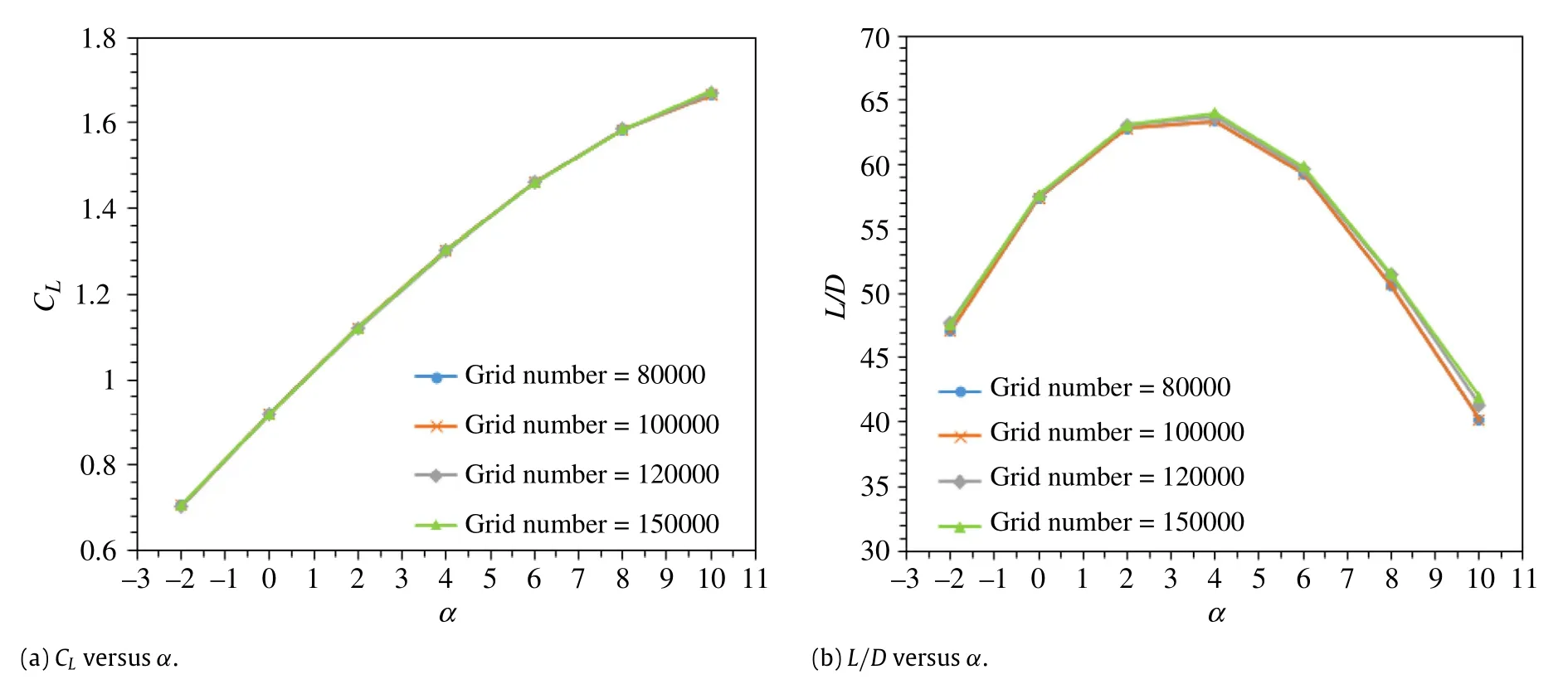
Fig.2.The dependence on the grids.
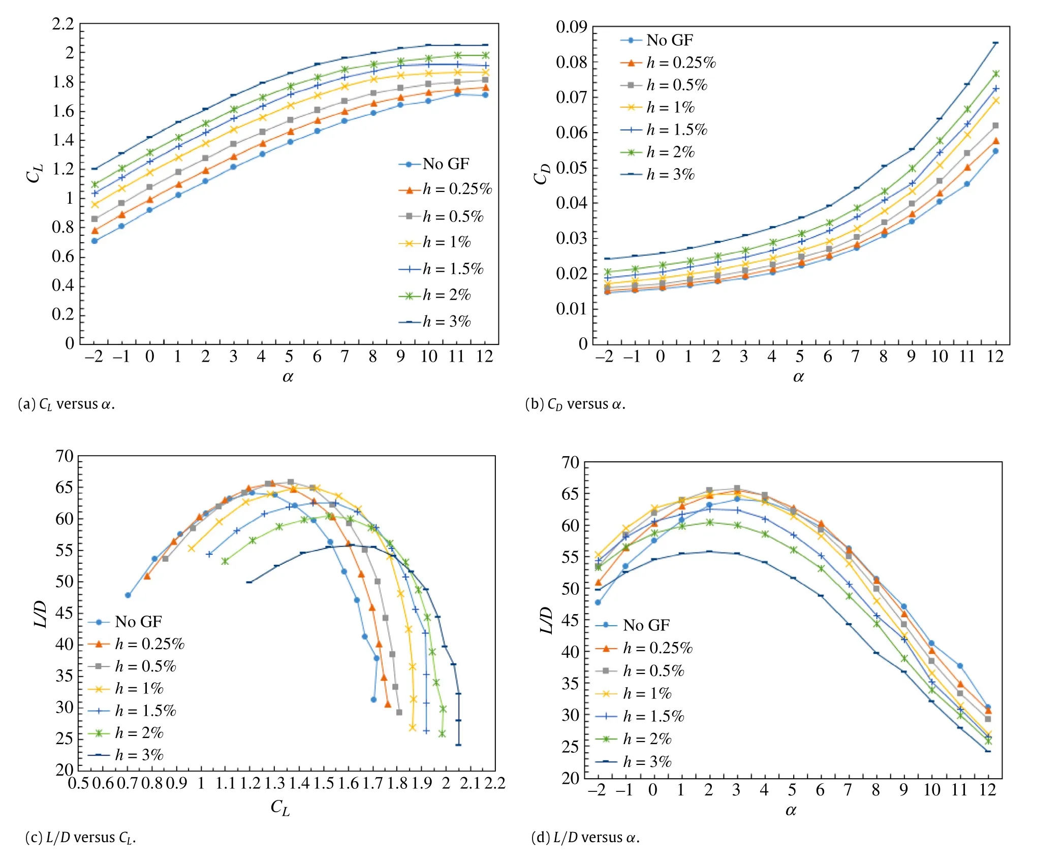
Fig.3.Aerodynamic coefficients.
As for boundary conditions,the inlet,top and bottom boundaries are defined as the velocity inlet boundary condition.The outlet boundary is defined as the outflow boundary condition. The surface of the airfoil and the GF are set as the no-slip wall condition.
Four types of grids are used in the present simulation to check the dependence of the results on the grids.The grid numbers are 8×104,1×105,1.2×105,and 1.5×10⁵,respectively.As is shown in Fig.2,the lift coefficient(CL)and lift-to-drag ratio(L/D)are in reasonable agreement for different grids,which indicates that thesimulation results are independent on the grid numbers for the four cases selected.Therefore,it is convincing to adopt the grid number of 1.2×10⁵in the present simulation.

Fig. 4. Pressure coefficient (CP) distribution on the airfoil with/without GF at different α.
Figure3 presentsthe aerodynamicforcecoefficientof SFYT15thick airfoil with and without a GF.In the present simulation,the data marked with‘No GF’show the aerodynamic coefficients curves of the clean airfoil,and the curves marked with‘h=x%’indicate the aerodynamic coefficients curves of the SFYT15thick airfoil with GF height ofx%C.As is shown in Fig.3(a),with the increase of GF height,the lift curves gradually shift upward.The larger the GF height is,the greater magnitude the curve shifts.At the designed cruise angle of attack(α= 3°),CLis enhanced by 12.9%and 32.8%forh= 0.5%and 2%, respectively.
Figure 3(b)shows the variation of drag with angles of attack at different GF heights.Obviously,GF also increases drag,and the largertheGFheightis,themorethedragincreasewillbe.Similarly, at the designed cruise angle of attack,drag coefficient(CD)is increased by 10.0%and 41.7%forh=0.5%and 2%,respectively. Thus,when the GF height is large,compared to the increase of lift,the drag increase becomes more significant.As the lift-to-drag ratio is an important factor in the flight range and endurance of theaircraft,analyzing the lift and drag merely is not comprehensive enough.It is needed to investigate the effect of GF on lift-to-drag ratio.
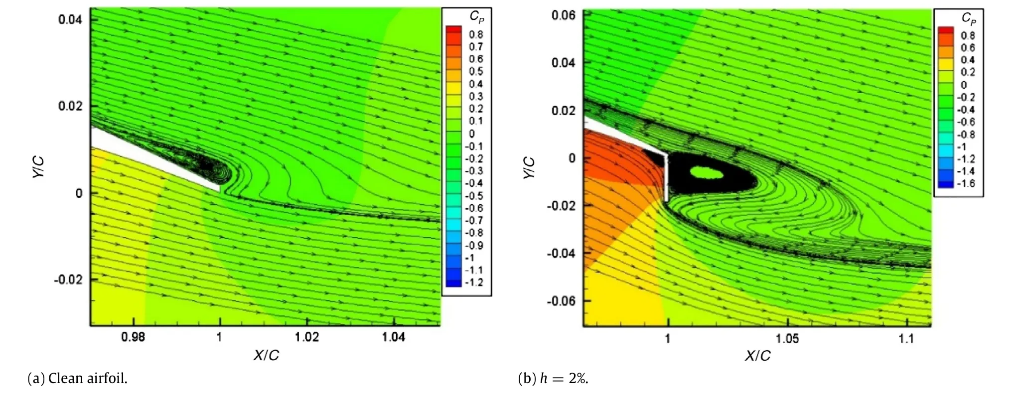
Fig.5.(Color online)Flow structure and pressure contours on trailing edge of SFYT15thick airfoil with/without GF atα=3°.
As is shown in Fig.3(c),for a given lift-to-drag ratio,the lift coefficientis enhancedwiththeincrease ofGF height.Ontheother hand,when the lift coefficient is in the range ofCL=1.2–1.7,the lift-to-drag ratio of airfoil with GF is increased compared with the clean airfoil.Specifically,when the lift coefficientCLis between 1.2 and 1.45,airfoil withh=0.5%GF has the optimal effect on the lift-to-drag ratio.Meanwhile,whenCLis between 1.45 and 1.7, airfoilwithh=1.0%GFisanoptimalchoice.Figure3(d)showsthe variation of lift-to-drag ratio withα,it can be seen that at a small angle of attack,GF can increase the lift-to-drag ratio of the airfoil. Atα=3°,the installation ofh=0.5%GF is an optimal design,in this case,the lift-to-drag ratio can be increased by 2.7%with a lift increment of 12.9%.
Figure 4 illustrates the pressure distribution on the airfoil with/without a GF.The Kutta condition of the trailing edge is changed when deploying a GF.The suction force of the upper surface of the airfoil is enhanced,and the lower surface pressure is increased.This effect raises the load capacity of the airfoil,and thenresultsinanincreasedCLoftheairfoil.ThelargertheGFheight is,the more the lift enhancement is.As is shown in Fig.4(a),when α=0°,the front 35%Cof the upper surface undergoes favorable pressure gradient.After that,the air flows smoothly along the upper surface of the airfoil without separation.In Fig.4(b),due to the increase ofα,the leading edge suction is increased,but the range of the favorable pressure gradient is reduced.In Fig.4(c), theleadingedgesuctionisfurtherincreased,andtheuppersurface of the airfoil undergoes adverse pressure gradient after 4%Cof the uppersurfaceatα=8°.Underthelargeadversepressuregradient, the flow tends to separate.It can be seen that the flow separation occurs at about 80%C.In the separation zone,the pressure remains constant and the pressure increment caused by the GF seems to be smaller.In the lower surface near the trailing edge and in front of the GF,the flow is also separated,forming a large recirculation zone,which makes the pressure of trailing edge increased.
In the present simulation,a comparison is made on the timeaveraged streamlines and pressure contours near trailing edge of the airfoil with/without GF atα = 3°.Figure 5(a)shows that there is a small separation bubble near the trailing edge without GF.However,in Fig.5(b),it is obvious that GF eliminates the small separation bubble on the upper surface,so that the air can flow smoothly along the upper surface.Thus,GF can increase the lift by delaying the flow separation in the trailing edge of the airfoil.
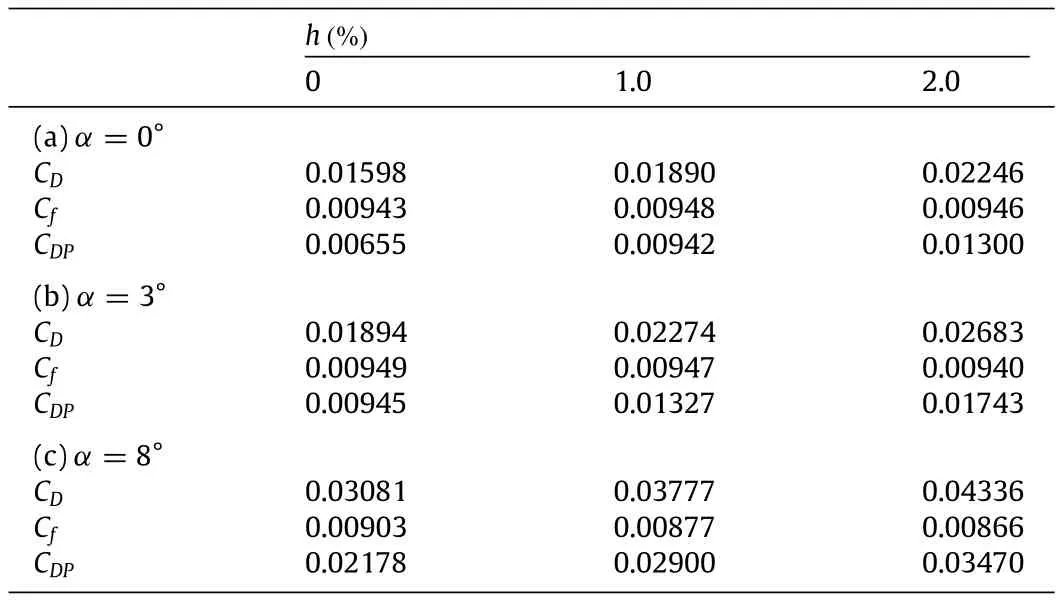
Table 1 Analysis of drag coefficient.
Simultaneously,a similar comparison is made atα=8°.As is shown in Fig.6(a),flow has separated at the position of 85%Cfrom the leading edge,resulting in a large separation bubble, which greatly reduces the suction on the upper surface of airfoil. However,Fig.6(b)illustrates that the flow separation on the upper surface is suppressed and the position of the separation is delayed to 90%Cfrom the leading edge when the GF is installed.As a result,the suction is larger than the clean airfoil and the lift is increased.At the same time,from the perspective of vortex,there is a wake region downstream of the leeward of GF,where a couple of counter-rotating vortex pairs exist.GF acts as a point vortex, which enlarges the circulation of the airfoil.The Kutta condition shifts from trailing-edge point of the airfoil to the lower edge of the GF,which results in lift enhancement.Moreover,the pressure contour shows that the windward side of the GF endures positive pressure and the leeward side endures the negative one,resulting in the drag increase of the airfoil.These are consistent with the results of Yu et al.[17].
In general,the drag of flow over airfoil includes friction drag, pressure drag,shock drag,and induced drag.In this paper,a twodimensional airfoil is considered at low speed,thus,it is enough to consider friction drag and pressure drag only.The total drag coefficientiscalculatedwithFluentsoftware,aswellasthespecific friction drag coefficient(Cf)and pressure drag coefficient(CDP). The results are shown in Table 1.

Fig.6.(Color online)Flow structure and pressure contours on trailing edge of SFYT15thick airfoil with/without GF atα=8°.
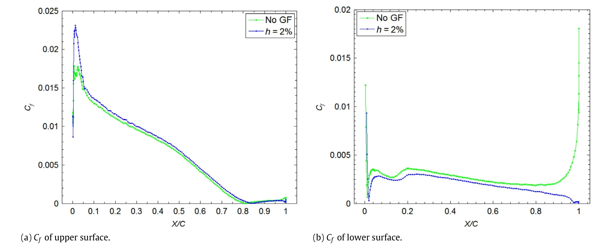
Fig.7.Cfof upper/lower surface atα=8°.
It can be seen from Table 1 that it is the dramatic increase of pressure drag which results in the increase of total drag of airfoil with GF.According to the analysis of the trailing edge flow,the windwardsideoftheGFendurespositivepressureandtheleeward sideenduresthenegativeone,andthepressuredragincreasesalot compared to the clean airfoil,which leads to the increase of total drag.From the data of frictional drag,it can be seen that the GF has a tendency to decrease the friction drag at a certain angle of attack. A comparison is made on the skin friction coefficient of the upper and lower surfaces with/without GF atα=8°.In Fig.7,on the upper surface,the leading edge suction is increased because of the GF so that the local flow rate is larger than that of the clean airfoil, whichmeansthefrictioncoefficientbecomeslarger.Meanwhile,at the trailing edge of the lower surface,the existence of GF leads to the flow separation.The flow is no longer attached to the entire lower airfoil surface,and the skin friction coefficient decreases. Combined with these two factors,the decrease of drag coefficient of the lower airfoil surface is dominant,resulting in the reduction of total friction coefficient.
This study further shows that even the carefully designed airfoil,GF can also be used to effectively improve the aerodynamic performance of the airfoil,i.e.,increasing lift coefficient as well as the lift-to-drag ratio.The larger the GF height is,the more obvious the lift-enhancement will be.When the lift coefficientCLis ranged from 1.2 to 1.7,airfoil with GF can provide higher lift-to-drag ratio at a fixed lift coefficient.Whenαis low,airfoil with GF can also improve the lift-to-drag ratio at a fixedα.In addition,this paper further reveals the mechanism of GF lift-enhancement and drag increase,and the drag increase can mainly be attributed to the pressure drag increment for flow around the GF.
[1]R.H.Liebeck,Designofsubsonicairfoilsforhighlift,J.Aircr.15(1978)547–561. http://dx.doi.org/10.2514/3.58406.
[2]R.Myose,M.Papadakis,I.Heron,Gurney flap experiments on airfoils,wings, and reflection plane model,J.Aircr.35(1998)206–211.http://dx.doi.org/10. 2514/2.2309.
[3]D.R.Jeffrey,X.Zhang,D.W.Hurst,Aerodynamics of Gurney flaps on a singleelement high-lift wing,J.Aircr.37(2000)295–301.http://dx.doi.org/10.2514/ 2.2593.
[4]Y.C.Li,J.J.Wang,P.F.Zhang,Effect of Gurney flaps on a NACA0012 airfoil,Flow Turbul.Combust.68(2002)27–39.http://dx.doi.org/10.1023/A: 1015679408150.
[5]Y.C.Li,J.J.Wang,P.F.Zhang,Influencesofmountinganglesandlocationsonthe effects of gurney flaps,J.Aircr.40(2003)494–498.http://dx.doi.org/10.2514/ 2.3144.
[6]R.Meyer,W.Hage,D.W.Bechert,et al.,Drag reduction on Gurney flaps by three-dimensional modifications,J.Aircr.43(2006)132–140. http://dx.doi.org/10.2514/1.14294.
[7]L.W.Traub,A.C.Miller,O.Rediniotis,Preliminary parametric study of Gurney flap dependencies,J.Aircr.43(2006)1242–1244.http://dx.doi.org/10.2514/1. 13852.
[8]T.S.Liu,J.Montefort,Thin airfoil theoretical interpretation for Gurney flap lift enhancement,J.Aircr.44(2007)667–671.http://dx.doi.org/10.2514/1.27680.
[9]L.Lee,T.Lee,Effect of Gurney flap on unsteady wake vortex,J.Aircr.44(2007) 1398–1401.http://dx.doi.org/10.2514/1.29555.
[10]J.J.Wang,Y.C.Li,K.S.Choi,Gurney flap–liftenhancement,mechanisms and applications, Prog. Aerosp. Sci. 44 (2008) 22–47. http://dx.doi.org/10.1016/j.paerosci.2007.10.001.
[11]Y.Amini,H.Emdad,M.Farid,Adjoint shape optimization of airfoils with attached Gurney flap,Aerosp.Sci.Technol.41(2015)216–228. http://dx.doi.org/10.1016/j.ast.2014.12.023.
[12]M.S.Chandrasekhara,Optimum Gurney flap height determination for‘lostlift’recovery in compressible dynamic stall control,Aerosp.Sci.Technol.14 (2010)551–556.http://dx.doi.org/10.1016/j.ast.2010.04.010.
[13]L.Hak-Tae,K.Ilan,B.Stefan,Flutter suppression for high aspect ratio flexible wings using microflaps,AIAA 2002-1717,in:43rd Conference of AIAA/ASME/ASCE/AHS/ASC Structures,Structural Dynamics,and Materials, 2002.http://dx.doi.org/10.2514/6.2002-1717.
[14]B.Stefan,K.Ilan,Flutter suppression using micro-trailing edge effectors, AIAA 2003-1941,in:44th Conference AIAA/ASME/ASCE/AHS/ASC Structures, Structural Dynamics,and Materials,2003.http://dx.doi.org/10.2514/6.2003-1941.
[15]D.T.Yen,C.Van Dam,F.Br?euchle,et al.Active load control and lift enhancement using MEM translational tabs,AIAA 2000-2422,2000. http://dx.doi.org/10.2514/6.2000-2242.
[16]F.R.Menter,Two-equation eddy-viscosity turbulence models for engineering applications,AIAAJ.32(1994)1598–1605.http://dx.doi.org/10.2514/3.12149.
[17]T.Yu,J.J.Wang,P.F.Zhang,Numerical simulation of Gurney flap on RAE-2822 supercritical airfoil,J.Aircr.48(2011)1565–1575.http://dx.doi.org/10.2514/ 1.C031285.
[18]P.F.Zhang,A.B.Liu,J.J.Wang,Aerodynamic modification of a NACA 0012 airfoil by trailing-edge plasma Gurney flap,AIAA J.47(2009)2467–2474. http://dx.doi.org/10.2514/1.43379.
[19]S.E.Rogers,F.R.Menter,P.A.Durbin,et al.A comparison of turbulence models in computing multi-element airfoil flows,AIAA-94-0291,in:32nd Aerospace Sciences Meeting&Exhibit,Reno,NV,USA,1994.
[20]T.Yu,J.J.Wang,P.F.Zhang,Numericalsimulation ofGurney flap on RAE-2822 supercriticalairfoil,J.Aircr.48 (2011) 1565–1575. http://dx.doi.org/10.2514/1.C031285.
[21]P.F.Zhang,A.B.Liu,J.J.Wang,Aerodynamic modification of a NACA 0012 airfoil by trailing-edge plasma Gurney flap,AIAA J.47(2009)2467–2474. http://dx.doi.org/10.2514/1.43379.
[22]D.L.Ma,Y.P.Zhao,Y.H.Qiao,et al.,Effects of relative thickness on aerodynamic characteristicsofairfoilatalowReynoldsnumber,Chin.J.Aeronaut.28(2015) 1003–1015.http://dx.doi.org/10.1016/j.cja.2015.05.012.
?Corresponding author.
E-mail addresses:hx1605106@buaa.edu.cn(X.He),jjwang@buaa.edu.cn (J.Wang),qingfengrumu@163.com(M.Yang),madongli@buaa.edu.cn(D.Ma), chyan@vip.sina.com(C.Yan),lpq@buaa.edu.cn(P.Liu).
http://dx.doi.org/10.1016/j.taml.2016.09.002
2095-0349/?2016 The Author(s).Published by Elsevier Ltd on behalf of The Chinese Society of Theoretical and Applied Mechanics.This is an open access article under the CC BY-NC-ND license(http://creativecommons.org/licenses/by-nc-nd/4.0/).
*This article belongs to the Fluid Mechanics
 Theoretical & Applied Mechanics Letters2016年6期
- Theoretical & Applied Mechanics Letters的其它文章
- A large eddy simulation of flows around an underwater vehicle model using an immersed boundary method
- Modelling windwave driven by typhoon Chan-Hom(201509)in the East China Sea
- Sufficiently diffused attachment of nitrogen arc by gasdynamic action
- On transition of type V interaction in double-wedge flow with non-equilibrium effects
- On the role of piezoelectricity in phonon properties and thermal conductivity of GaN nanofilms
- Coriolis effect on responses of rotating thin piezoelectric hollow cylinder