Modeling of a Planar Nine-Way Metamaterial Power Divider/Combiner
2015-11-18 10:11:47WeiChiangLeeandTahHsiungChu
Wei-Chiang Lee and Tah-Hsiung Chu
Modeling of a Planar Nine-Way Metamaterial Power Divider/Combiner
Wei-Chiang Lee and Tah-Hsiung Chu
—Analysis of the scattering parameters(S-parameters) of planar N-way metamaterial power dividers/combiners mostly uses commercial microwave circuit simulators due to the large circuit size involved. This paper presents an efficient circuit modeling approach, which is based on the multi-input and multi-output transmission matrix (T-matrix) method, to analyze the S-parameter of a planar nine-way metamaterial power-divider/combiner structure. S-parameter computation results are shown in good agreement with the simulation results by using the Agilent advanced design system (ADS) and measurement results. The computation time of an N-way metamaterial power divider/combiner with N=5,9, 13, and 17 using T-matrix method is also compared with those of ADS and AWR Microwave Office (MWO)to demonstrate its computational efficiency.
Index Terms—Circuit analysis, metamaterial,microwave circuit, power combiner, power divider.
1. Introduction
Power dividers/combiners are passive devices which are used to properly divide the input power to solid-state devices through a power divider then combine the output power from the power divider through a power combiner to deliver more output power than that of a single device. Thus developing microwave power-dividing/combining techniques[1]to achieve low loss and high combining efficiency is desirable.
Recently, metamaterials with a negative refractive index with the left-handed (LH) propagation behavior are extensively applied to microwave devices. Specifically,they are composed of one-dimensional or two-dimensional(2-D) right-handed (RH) and LH transmission lines called composite right/left-handed (CRLH) transmission lines. By properly operating CRLH transmission lines at the infinite wavelength frequency, metamaterials can have a zero-phase shift characteristic along the structure to give an equal magnitude and phase distribution. Based on this characteristic, planar metamaterial power dividers[2],[3]using the positive refractive index (PRI) material and zero refractive index (ZRI) material have been presented. Specifically, the PRI material is composed of 2-D RH unit cells, while the ZRI material is realized by arranging 2-D RH and LH unit cells in a checkerboard tessellation[2], or by using only LH unit cells operated at the infinite wavelength frequency to give the zero-phase shift characteristic[3].
The planar structures and low-loss characteristics of metamaterial power dividers/combiners[2],[3]make them suitable for integrating with amplifiers to realize planar power-combined amplifiers[4]. However, the possible approaches to analyze their scattering parameters(S-parameters) can only use commercial microwave circuit simulators. With the increasing circuit size, or equivalently,the increasing number of unit cells, the analysis of N-way metamaterial power-divider/combiner structures by using commercial microwave circuit simulators, such as the Agilent advanced design system (ADS)[5]used in our previous work[3], shows computational inefficiency.
In this paper, an efficient circuit modeling approach to analyze the planar metamaterial power divider/combiner structures is presented. The analysis is based on the multi-input and multi-output transmission matrix (T-matrix)method[6], which is applied to solve the equivalent circuit of a power/ground pair.
2. Design
Fig. 1 (a) shows the schematic of a planar nine-way metamaterial power divider/combiner designed for the power combining of nine amplifiers[4]. It is composed of RH unit cells for PRI material and LH unit cells for ZRI material, whose structures are shown in Fig. 1 (b).
A nine-way power divider/combiner is designed on a 1.575-mm-thick Rogers RT/Duroid 5880 substrate with relative dielectric constant εr=2.2 and loss tangent tanδ=0.0009. The operating frequency is 1 GHz, and the reflection and transmission coefficients of the nine-way divider structure in Fig. 1 (a) are -50 dB and -10 dB,respectively[3]. The detailed design parameters can refer to[3] and [4].
3. Formulation
To acquire its S-parameter, the nine-way power-divider/combiner structure is analyzed by dividing it into fourteen columns with each consisting of nine unit cells, as shown in the fourteen dashed rectangular boxes of Fig. 1 (a). The T-matrix, relating the input voltages and currents to the output voltages and currents of unit cells of each column, is firstly established. The T-matrix of the entire power-divider/combiner structure is further obtained by multiplying the T-matrices of fourteen columns and is then converted into the scattering matrix (S-matrix) to give the S-parameters at the specific ports.
For the convenience of analysis, the structures of 2-D LH and RH unit cells in Fig. 1 (b) are converted into four-port T-networks composed of four identical impedance elements in series and one admittance element in shunt, and they are respectively represented by ZsL/2, YpL, and ZsR/2,YpRas shown in Fig. 2.
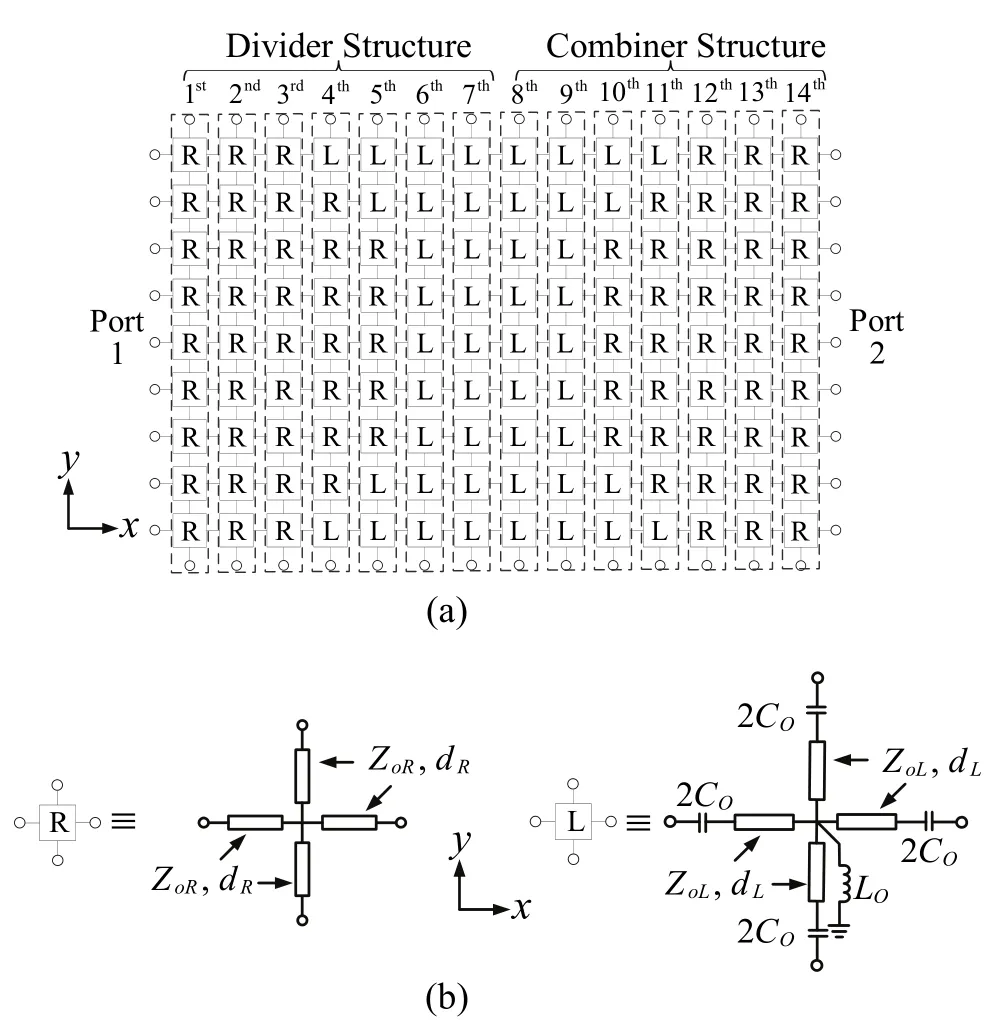
Fig. 1. Schematic of divider/combiner and unit cells: (a) planar nine-way power divider/combiner and (b) R and L representing RH and LH unit cells.
As shown in Fig. 1 (a), the T-matrices of fourteen columns with each consisting of nine unit cells can be represented by the T-matrix Tiwhere i=1, 2, ???, 14 and are given by

where

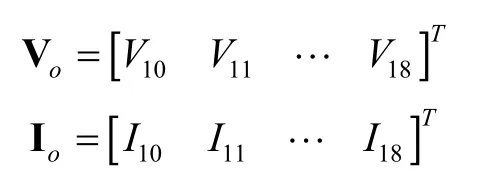
which are the nine inputs and nine outputs of the nine unit cells for each column, and
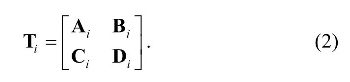
In (1) and (2), Tiis of the size of 18×18, and the sub-matrices Ai, Bi, Ci, and Diare all of the size of 9×9.
Each column is further decomposed into three distinct sub-columns to obtain the T-matrix Tiwith the product of matrices of three sub-columns as

where Th1,i, Tν,i, and Th2,iare all of the size of 18×18. The T-matrixiT given in (3) is then formulated as the following by taking the 1st column as an example.
As shown in Fig. 2, the 1st column is represented by the number of unit cells and has an excitation source at the 5th cell with the representation of three sub-columns at the right side. It is noted that except the 5th cell, the open-circuit microstrip lines in x- and y-directions for the other cells are considered in their shunt elements YpR, and resistance elements Zso/2 of 5 k? are used to connect input voltages Vj, where j=1, 2, ???, 9 (j≠5) in the left sub-column. By applying Kirchhoff’s circuit laws to the nodes of the circuit of three sub-columns in Fig. 2, the T-matrices relating the input voltages and currents to the output voltages and currents for each sub-column can then be obtained.

Fig. 2. Equivalent circuit for the 1st column.
The T-matrix Th1,1of the left sub-column in T1can be represented as

where


Notably, I and O matrices are 9×9 identity and zero matrices, andis a 9×9 diagonal matrix. For the right sub-column in T1, the T-matrixis given by
where

For the middle sub-column in T1, the T-matrix Tν,1is given by


The matrices of the remaining thirteen columns for the power-divider/combiner structure can be derived in the same way, which are not shown here. The overall T-matrix of the power divider/combiner given in Fig. 1 (a),consisting of fourteen columns, is then obtained by multiplying the matrices of fourteen columns:

To acquire its S-matrix of the nine-way power-divider/combiner circuit, the T-matrix T is then transformed by[7]

to give the reflection and transmission coefficients at the specific ports. In (9), ZCis the port reference impedance.
The computation of the S-parameters of the nine-way power divider/combiner is described in a summary by an algorithm and flow chart as shown in Fig. 3. It is worthy to note that the presented T-matrix method here can be directly applied to analyze the nine-way power-combiner amplifier[4]with the modification of (8), which is the product of T-matrices of 15 columns including the divider for the 1st to 7th column, amplifiers for the 8th column, and the combiner for the 9th to 15th column.

Fig. 3. Algorithm and flow chart for the computation of S-parameters of the nine-way power divider/combiner: (a)algorithm steps and (b) flow chart.
4. Results
The nine-way power-divider/combiner circuit is shown in Fig. 4. Two simulation studies are performed for the comparison with the measured results. One is performed by a MATLAB program by using the derived T-matrix formulation given in Section 3 and the other uses Agilent ADS.

Fig. 4. Photograph of a planar nine-way power-divider/combiner circuit.
Fig. 5 shows that the simulated and measured S-parameters are with good agreement. In the band of 1.025 GHz to 1.05 GHz, the input and the output reflection coefficients are less than -10 dB, and the measured transmission coefficient is from -1.6 dB to -1.17 dB. At 1.038 GHz, the measured input reflection and transmission coefficients are -20 dB and -1.17 dB, respectively. The measured results of combining efficiency given by[8]

are with an average value of 88% from 1.025 GHz to 1.05 GHz. It is worthy to note that the narrow-band result is due to the bandwidth limitation of ZRI materials[4]and may be improved by using non-foster active elements[9]in ZRI materials for the broader bandwidth design.

Fig. 5. Simulated and measured results of reflection and transmission coefficients.
As indicated in Section 3, due to the fact that the T-matrices for the three sub-columns in each column are sparse, the memory usage and CPU time on analyzing this power-divider/combiner structure can be effectively reduced, especially for the increasing number of unit cells. To demonstrate this result, the computation time for the S-parameter simulation of an N-way metamaterial power divider/combiner with N=5, 9, 13, and 17 using the T-matrix, ADS, and AWR Microwave Office (MWO)[10]approaches, respectively, is presented for comparison, as shown in Table 1.
Notably, all the simulations in Table 1 with each having 1601 frequency points are conducted on a computer with Windows Vista 64-bit Intel?Core? i7 2.67 GHz and 9 GB RAM. From Table 1, compared with ADS, the computation time for the T-matrix method is shown slightly increased with the number of unit cells especially in the two cases of N=13 and 17, and the computation time for ADS is about ten to twenty-six times than that for the T-matrix. The simulation time for MWO is performed by using its sparse solver to demonstrate the fact that using the T-matrix method is more computationally efficient, especially as N becomes large.

Table 1: Computation time comparison
5. Conclusions
An efficient circuit modeling approach for analyzing a planar nine-way metamaterial power divider/combiner has been presented. The analysis is based on the multi-input and multi-output T-matrix method. Good agreement between the analytical results and the results of ADS simulation and measurement is acquired.
To demonstrate its computational efficiency of the T-matrix method, the computation time for the S-parameter simulation of the planar N-way metamaterial power divider/combiner with N=5, 9, 13, and 17 using the T-matrix, ADS, and MWO approaches is presented for comparison, respectively. The computation time for the T-matrix method is about one-tenth to one-twenty-sixth of that for ADS. Moreover, in the cases of N=13 and 17, the computation time for the T-matrix method by using the sparse solver is only increasing slightly compared with that for MWO, which demonstrates its efficient computational efficiency on analyzing large N-way power-divider/ combiner structures.
[1] K. J. Russell, “Microwave power combining techniques,”IEEE Trans. on Microwaνe Theory and Techniques, vol. MTT-27, no. 5, pp. 472-478, May 1979.
[2] K. W. Eccleston, “Planar N-way metamaterial power divider,” in Proc. of Asia-Pacific Microwaνe Conf., 2009, pp. 1024-1027.
[3] W. C. Lee and T. H. Chu, “Design and measurement of a planar 9-way metamaterial power divider,” in IEEE Microwaνe Symposium Digest, 2012, pp. 1-3.
[4] W. C. Lee and T. H. Chu, “Design and power performance measurement of a planar metamaterial power-combinedamplifier,” IEEE Trans. on Microwaνe Theory and Techniques, vol. 61, no. 6, pp. 2414-2424, 2013.
[5] Adνanced Design System (ADS), Agilent Technologies, Palo Alto, 2008.
[6] J. Kim and M. Swaminathan, “Modeling of irregular shaped power distribution planes using transmission matrix method,” IEEE Trans. on Adνanced Packaging, vol. 24, no. 3, pp. 334-346, Aug. 2001.
[7] H. Lee, K. Choi, K. L. Jang, T. Cho, and S. Oh, “A new efficient equivalent circuit extraction method for multi-port high speed package using multi-input multi-output transmission matrix and polynomial curve fitting,” in Proc. of the 53rd Electronic Component and Technology Conf.,2003, pp. 1582-1588.
[8] P. Jia, L. Y. Chen, N. S. Cheng, and R. A. York, “Design of waveguide finline arrays for spatial power combining,”IEEE Trans. on Microwaνe Theory and Techniques, vol. 49,no. 4, pp. 609-614, Apr. 2001.
[9] S. Saadat, M. Adnan, H. Mosallaei, and E. Afshari,“Composite metamaterial and metasurface integrated with non-foster active circuit elements: a bandwidthenhancement investigation,” IEEE Trans. on Antennas and Propagation, vol. 61, no. 3, pp. 1210-1218, Mar. 2013.
[10] Microwaνe Office (MWO), Version 10.08r, AWR Technology, El Segundo, 2013.

Wei-Chiang Lee was born in Kaohsiung in 1981. He received the B.S. degree in electrical engineering from National Kaohsiung University, Kaohsiung in 2004, and the M.S. and Ph.D. degrees in communication engineering from National Taiwan University,Taipei in 2006 and 2013, respectively. He is currently a postdoctoral research fellow with the Department of Electrical Engineering, National Taiwan University. His research interests include microwave circuits,metamaterials, and power combining techniques.

Tah-Hsiung Chu received the B.S. degree from National Taiwan University, Taipei in 1976 and the M.S. and Ph.D. degrees from the University of Pennsylvania, Philadelphia in 1980 and 1983, respectively, all in electrical engineering. From 1983 to 1986, he was a member of technical staff with the Microwave Technology Center, RCA David Sarnoff Research Center,Princeton, NJ. Since 1986, he has worked with the Department of Electrical Engineering, National Taiwan University, where he is now a professor in electrical engineering. His research interests include microwave-imaging systems and techniques, microwave circuits and subsystems, microwave measurement, and calibration techniques.
Manuscript received December 31, 2014, revised May 23, 2015. This work was supported by MOST under Grant No. MOST 103-2221-E-002-050.
W.-C. Lee is with the Department of Electrical Engineering, National Taiwan University, Taipei (e-mail: r93942052@ntu.edu.tw).
T.-H. Chu is with the Department of Electrical Engineering, National Taiwan University, Taipei (Corresponding author e-mail: thc@ntu.edu.tw).
Digital Object Identifier: 10.3969/j.issn.1674-862X.2015.01.013
登錄APP查看全文
 Journal of Electronic Science and Technology
2015年2期
Journal of Electronic Science and Technology
2015年2期
- Journal of Electronic Science and Technology的其它文章
- QCM Sensors Based on PEI Films for CO2Detection
- Energy-Based Collaborative Spectrum Sensing for Cognitive UWB Impulse Radio
- Monitoring of PON System Using Compound Surveillance Technique
- Design and Realization of an NFC-Driven Smart Home System to Support Intruder Detection and Social Network Integration
- Robust Stability of a Class of Fractional Order Hopfield Neural Networks
- Novel Sequence Number Based Secure Authentication Scheme for Wireless LANs