Based on Cortex-M4 torus worm tester full closed loop control system
2015-11-03 07:02:04YongchunYANG
機(jī)床與液壓 2015年3期
Yong-chun YANG
(College of Electromechanic Engineering, Xinjiang Vocational﹠Technical College of Communications, Urumpi 831401,China)
?
Based on Cortex-M4 torus worm tester full closed loop control system
Yong-chun YANG*
(College of Electromechanic Engineering, Xinjiang Vocational﹠Technical College of Communications, Urumpi 831401,China)
In view of the torus worm tester system control and positioning accuracy, the Cortex - M4 as the main controller, the control stepper motor to drive the objective table movement, stepper motor adopts closed loop control. the grating ruler for real-time detection ofXYZguide information, the grating signal as the feedback signal, constitute a closed-loop motion control system, realize coordinate system XYZ axis movement and high precision positioning of the turntable rotation. Stepper motor driver uses hardware and software subdivision method, overcome the stepper motor step crawl and lost phenomenon. Experiments show that the system adopts the closed loop control, step motor subdivision method of software and hardware, and realizes the three axes of ±2 μm precision positioning, to ensure the torus worm tester accurate measurement.
Torus worm, Grating ruler, Closed loop control, Software and hardware subdivision
1 Introduction
With the development of science and technology, modern industrial technology especially in the machinery industry the transmission properties of the mechanical equipment has a higher request. With the invention of the torus worm and theoretical development, worm transmission performance is further optimized and improved. So, torus worm in machining and mechanical applications is widely spread. However worm drive performance better ring surface worm drive has obvious disadvantages, that is sensitive to worm machining error and tooth deformation[1-3]. In the process of practice, small tooth shape error can lead to tooth surface in ring surface worm drive process edge contact. At the same time, the shape of the torus worm itself is more complex, the gear tooth shape, tooth thickness is different, the pitch size is different also. So torus worm manufacturing error detection is also very complicated, Most domestic manufacturer also can evaluate its processing through the tooth surface contact spots as a result, can’t detect its machining precision and it does not provide specific quantitative indicators[4-5]. The system adopts the closed loop control, software and hardware subdivision of stepper motor, to realize the three axes ±2 μm precision positioning.
2 The mechanical structure of the torus worm detection system
Mechanical structural design to be able to meet the requirements of rotating space coordinate system, in order to realize the rod probe and measured torus worm real-time synchronous rotation.
Mechanical structure is composed of three coordinate structure and gate when the turntable structure, including three coordinates of each coordinate axis by stepper motor, coupling, ball screw, horizontal guide rail, grating ruler and base composition, inductive micrometer measuring head installed on the vertical axis. Mechanical structure is shown in Fig.1.
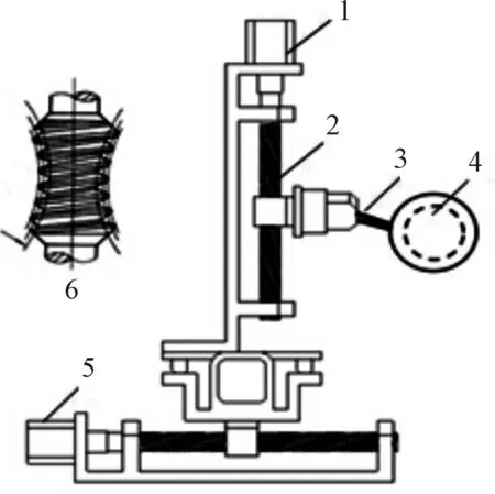
1.stepper motor ofZaxis; 2.ball screw; 3.induction micrometer head; 4.torus worm main view; 5.stepper motor ofYaxis; 6.torus worm vertical view
Fig.1 System mechanical structure diagram
3 Test system of closed loop control
Stepper motor provides the power of the whole system, through coupling with ball screw connection, the direction of rotation movement into horizontal drives the objective table movement.
Grating ruler detection the location information of guide real-time, and the grating signal as the feedback signal, constitute a closed-loop motion control system, implementation of inductive micrometer measuring head of the high precision positioning. Dotted box in Fig.2 is a closed-loop motion control system. In the process of the concrete measure, inductive micrometer probe in following the movement state, and measured torus worm can be set arbitrary exercise movement.
Measured worm first, measurement and control system installed in the end of the position of the Angle sensor feedback information, then on the basis of worm transmission characteristics determine the motion parameters of time grating turntable, the final measurement and control system a corresponding instruction control time grating turntable system following movement, the same is the closed-loop motion control mode are used. Closed-loop control system diagram as shown in Fig.2.

Fig.2 Detection system closed-loop control principle diagram
4 Control system hardware circuit design
4.1 Displacement sensor signal conversion circuit
In the detection system, three coordinate use high precision grating ruler by Hydehan company. Grating ruler feedback length location information to STM32F407. With the X axis grating ruler, for example. original signal output of grating ruler respectively isA,B,R. Through differential signal processing chip MAX3093 transform into three road single-ended signals (OG_AOG_BOG_R), among themA,Btwo way is processed for single-ended grating signal phase difference of 90°, R as a reset signal [6]. Three way single-ended signal after plastic surgery to STM32F407 pulse counting processing chip. X axis grating ruler signal conversion circuit is shown in Fig.3.
In order to match the STM32F407 electrical signals, need through the inverter to Alin, Blin, Rlin electrical signals into 0-3.3 V logic signalsOG_A,OG_B,OG_R, then, the three logic electrical signals sent to the STM32F407 for signal detection. TheXaxis grating signal conversion circuit is shown in Fig.3.Three single-ended signal after reshaping send STM32F407 processor for counting pulse.
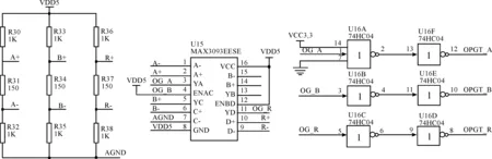
Fig.3 Grating ruler signal conversion circuit
4.2 Stepper motor control circuit
According to the existing experimental facility and control requirement, choose the two-phase hybrid stepper motor and matched actuator. step within 1.8°, phase current 3 A, dc drive voltage 24-40 V, the largest static torque of 1.2 Nm, characteristic of startup is 390 n/m. To achieve the highest control accuracy, subdivision number should be set to maximum. Actuator has to input voltage signal or current signal requirement, it needs to design the interface circuit of controller and actuator. The SN74LS245 is an Octal Bus Transmitter/Receiver designed for 8-line asynchronous 2-way data communication between data buses. The STM32F407 output signal (including motor enable signal, the direction of signal and the pulse signal) has 3.3 V high-level voltage convert to actuator required 5 V by SN74LS245, and enhanced driving ability. The drive circuit is shown in Fig.4.
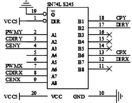
Fig.4 Stepper motor drive circuit
5 Control system software design
According to the classical control theory, a closed-loop position control method of stepper motor can be divided into unidirectional and bidirectional approximation [7], in general, bidirectional approximation positioning faster than unidirectional approximation approach, but two-way approach bring retrace error. This design uses the software subdivision method of one-way, as shown in Fig.5, when it don’t arrive preset position, prevent outrange, then the remaining steps of to half approach every time. Stepper motor turning angle is very close to the preset value, even with the software subdivision may also be more than the preset value, then the stepper motor reverse approximation.
STM32F417 processor produces precise PWM drive stepper motor, stepper motor motion depends on PWM pulse. PWM pulse frequency controls the speed of the stepper motor, this system adopts the software and hardware PWM pulse subdivision technology, to realize the high precision positioning of the three-dimensional coordinate axis. First STM32F417 through a serial port connected to a machine instruction, PC receives the
Angle values converted into the number of pulse stepper motor, and then according to the instruction on the number of pulse control stepping motor motion, the grating ruler reading head position will be the actual value in real-time feedback to the STM32F417, a closed loop system can be constituted to improve the pointing accuracy.
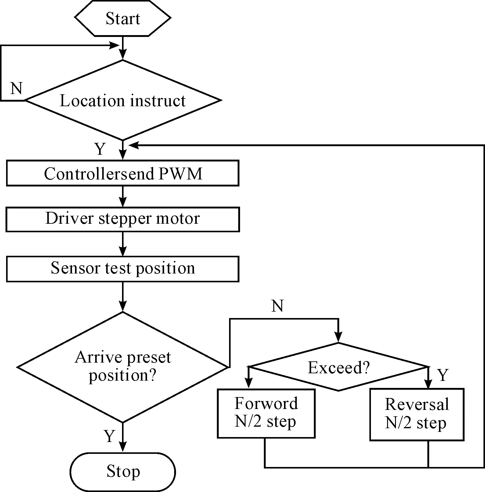
Fig.5 Software subdivision design flow chart transposition
6 The experiment
Three axis positioning principle is the same, the high precision positioning in X axis under the experimental experiment as an example, the X coordinate of physical diagram is shown in Fig.6. At the side of the guide rail laying length for the movement range of the grating ruler, grating ruler and guides to keep parallel, measuring head installed on the grating ruler. Within the base slot bracket is installed on ball screw, screw through the coupling and the drive motor card together.
System uses the grating ruler as location information for reference, to detect the state of motion of guide rail and the position information feedback to STM32F417, so as to constitute a closed loop measurement and control systems. In order to improve the accuracy of output signal of grating ruler, will be four times grating ruler signal subdivision. The closed-loop control system compared with the open-loop control system eliminates step “l(fā)ost” and “shock”, so as to improve the positioning precision of the detection system. the X coordinate of precision positioning as shown in Fig.7. Error has ±2 μm precision positioning.
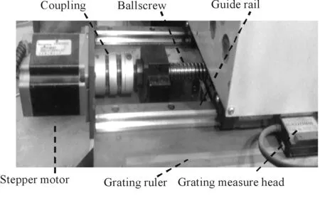
Fig.6 The X axis mechanical structure diagram
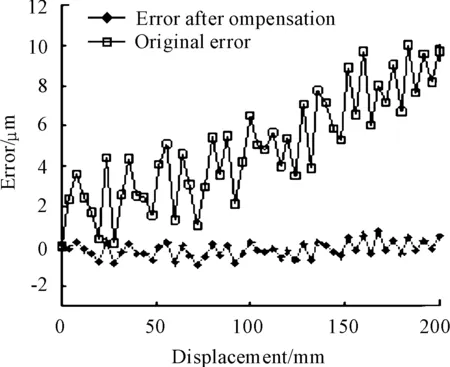
Fig.7 The location error curve
7 Conclusions
The full closed loop control of the system is realized by the grating ruler and time grating turntable as the position feedback detection. Three axis positioning accuracy is ±2 μm by hardware and software subdivision, error correction and compensation, ensure the torus worm tester accurate measurement.
[1]SUN Shumin, ZHANG Guanghui. Torus worm manufacturing error analysis of the test[J]. Journal of Chongqing University (Natural Science Edition), 2003, 26(3): 130-132.
[2]QIN Datong,YAN Jia, ZHANG Guanghui. Plane enveloping ring surface worm based on coordinate measuring method of high precision manufacturing[J]. Journal of Mechanical Engineering, 1997, 33: 59-65.
[3]JI Yongjun, LAO Qicheng. Based on gear measurement center of torus worm measurement research[J]. The technology of Tool, 2008(42): 102-105.
[4]XIE Qihe, PENG Donglin, CHEN Xihou. Based on architecture CortexM4 and two-dimensional subdivision technology of high precision positioning control system[J]. The computer measurement and control, 2013, 21(10): 2692-2693, 2673.
[5]LU Yihua, ZHANG Xianmin. Two-dimensional precision positioning system error analysis and compensation[J]. Mechanical design, 2009, 26: 59-62.
[6]Kulkarni, Amol S, El-Sharkawi, Mohamed A. Intelligent Precision Position Control of Elastic Drive Systems[J]. IEEE Transactions on Energy Conversion, 2001, 16(1): 26.
[7]Zhang Tao. Stepper motor rapid positioning method research[M]. Xi’an: The Northern Industrial University, 2005.
[8]LIAO Yikui. ARM Cortex-M4 embedded field development essence solution based on STM32F4 [M]. Beijing: Beijing University of Aeronautics and Astronautics Press, 2013.
[9]YANG ShaoYan, HUANG Lichuang, LIU Li. High precision stepper motor control method [J]. Journal of Photoelectric Technology, 2006, 21(1): 37-39.
[10]Meng Jun, Zhengxing Zhang, LiuBo. Two phase stepping motor subdivision drive design and implementation [J]. Electric applications, 2007, 26(12): 84-87.
[11]Huaiqong Li, ChenQian, Xiaodong Zhuang. New type of grating signal digital subdivision technology and its error analysis [J]. Journal of electronic measurement and instrument, 2001, 15(3): 71-75.
基于Cortex-M4的環(huán)面蝸桿檢測儀的全閉環(huán)控制系統(tǒng)
楊永春*
新疆交通職業(yè)技術(shù)學(xué)院 機(jī)電工程學(xué)院, 烏魯木齊 831401
針對環(huán)面蝸桿檢測儀系統(tǒng)控制及定位精度的需要,采用Cortex-M4作為主控制器,控制步進(jìn)電機(jī)驅(qū)動(dòng)載物臺運(yùn)動(dòng),步進(jìn)電機(jī)采用閉環(huán)控制。光柵尺實(shí)時(shí)檢測XYZ導(dǎo)軌的位置信息,并把光柵信號作為反饋信號,構(gòu)成閉環(huán)運(yùn)動(dòng)控制系統(tǒng),實(shí)現(xiàn)坐標(biāo)系中XYZ軸的運(yùn)動(dòng)和時(shí)柵轉(zhuǎn)臺旋轉(zhuǎn)的高精度定位。步進(jìn)電機(jī)的驅(qū)動(dòng)采用軟硬件細(xì)分方法,克服了步進(jìn)電機(jī)爬行和丟步現(xiàn)象。實(shí)驗(yàn)表明:該系統(tǒng)采用全閉環(huán)控制、步進(jìn)電機(jī)軟硬件細(xì)分方法,實(shí)現(xiàn)了三坐標(biāo)軸±2 μm 的精密定位,保證了環(huán)面蝸桿檢測儀的準(zhǔn)確測量。
環(huán)面蝸桿;光柵尺;全閉環(huán)控制;軟硬件細(xì)分
12 September 2014; revised 15 December 2014;
Yong-chun YANG, Associate professor. E-mail: yyc2152090@163.com
10.3969/j.issn.1001-3881.2015.18.022 Document code: A
TP212.9
accepted 20 March 2015
Hydromechatronics Engineering
http://jdy.qks.cqut.edu.cn
E-mail: jdygcyw@126.com
- 機(jī)床與液壓的其它文章
- Manufacturing of self-lubricating diamond tools with Ni-Cr alloy adding with Ni/C
- Vibration response analysis of a lathe spindle by using the ANSYS finite element method
- Car following model with consideration of the vehicle’s mechanical inertia effect and its stability analysis
- Software design for spur gear tooth thickness based on MATLAB/GUI
- Dynamic study on ultrasonic horn
- Analysis and research of OPC technology in coal mine monitoring data transmission system