Research of Oil Film Stiffness Influence on Shafting Torsional Vibration Based on Wave Approach
2015-05-02 19:36:32YANGYongCHEChidongTANGWenyong
船舶力學 2015年9期
YANG Yong,CHE Chi-dong,TANG Wen-yong
(1.State Key Laboratory of Ocean Engineering,Shanghai Jiao Tong University,Shanghai 200030,China; 2.Marine Design&Research Institute of China,Shanghai 200011,China)
Research of Oil Film Stiffness Influence on Shafting Torsional Vibration Based on Wave Approach
YANG Yong1,2,CHE Chi-dong1,TANG Wen-yong1
(1.State Key Laboratory of Ocean Engineering,Shanghai Jiao Tong University,Shanghai 200030,China; 2.Marine Design&Research Institute of China,Shanghai 200011,China)
Shafting vibration calculation is put out to ensure better reliability of main propulsion system with gearbox.The shafting system is modeled into continuous and discrete sub-systems,taking oil film stiffness of gearbox into consideration simultaneously.Wave approach and transit matrix method are used to investigate the displacement and stress fields in continuous and discrete sub-system respectively.And vibrations in different modes in both sub-systems are coupled by using dynamic equilibrium and continuity condition to deduce the global equations governing the motion of shafting. The torsional vibration calculation is then applied to research a certain LNG vessel with gearbox. It is shown that the vibration model with considered oil film stiffness is more reliable for the shafting system with gearbox.The calculated results show that the max torsional stress appears in lower speed with oil film stiffness of gearbox ascending,and the barred-speed range is influenced greatly. This is helpful to prevent ship shafting accidents due to some poor shafting vibration calculation.
shafting;torsional vibration;wave approach;oil film stiffness
0 Introduction
This paper is concerned with the vibration calculation of propulsive shafting.In recent years,more and more attention has been paid to shafting vibration for the sack of habitability on board[1-5].Some poor vibration prediction affects both the normal running and the reliability of propulsive shafting.The normal calculation methods of shafting torsional vibration include dynamic stiffness matrix method,finite element method,statistical energy analyses,experience equation,and so on[6-8].According to the criterion of most Classification Society,torsional vibration is calculated discretely.That is to say,the propulsive shafting under certain vibration mode is modeled as the combination of a series discrete masses and springs connecting each other without taking any oil film stiffness effects into consideration.
These poor torsional vibration calculations make shafts be broken where the maximumstress takes place.If the vibration appears in shafting couplings,connected bolts will rupture teeth faces or disjunction are caused.For high elastic couplings,torque leads up to rupture or disjunction sooner or later.As torque is larger than transmission torque in gearboxes,corrosive temperature is risen up to burn.In the same time,generators do not work stably,and machine body quivers strongly under the torque influences.All these can be avoided by the accurate vibration calculation during ship design.
For more accurate shafting vibration prediction on board,a torsional vibration model with discrete and continuous sub-systems is put out in this paper taking oil film stiffness of gearbox into consideration simultaneously.And a torsional vibration for a certain LNG vessel with gearbox is applied to safe evaluation so as to predict more accurate shafting vibration on board.
1 Continuous and discrete sub-systems
1.1 Model description
According to the shafting arrangement,the large mass such as propeller,flange,coupling, etc are simplified into concentrated mass.The shaft is dealt with continuous medium,bending, prolonging,and torsional influence are considered.Because diesel crank and crank pin dimension are far less than structure wave length in the shaft,diesel is dealt with a discrete sub-system.The shafting vibration model consists of two parts which are shafting continuous sub-system and diesel discrete sub-system.The equivalent chart of torsional vibration is shown as Fig.1.
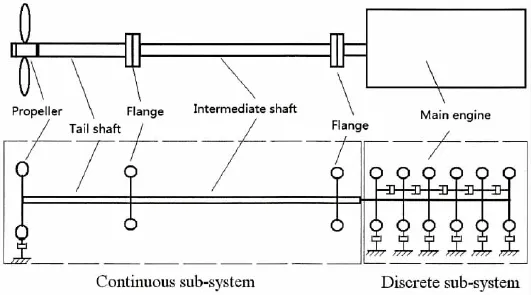
Fig.1 The torsional vibration inertia chart of continuous and discrete sub-systems
The equivalent system of shafting vibration consists of two parts which are shaft continuous and diesel discrete sub-systems.For the propeller and diesel synergy,shafting torsional vibration is calculated with oil film stiffness of gearbox.
1.2 Torsional vibration
A unit dx is selected in x position on the shaft,ρ is the density of the unit volume,sectional polar moment of inertia is Ip,the torsion angle in x section is θ,and the torque is T in Fig.2.
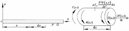
Fig.2 Shaft segment showing force and torsional deformation
If torsional vector and external normal direction in the section are the same,denotation is positive.The continuous shaft motion equation of torsional vibration is
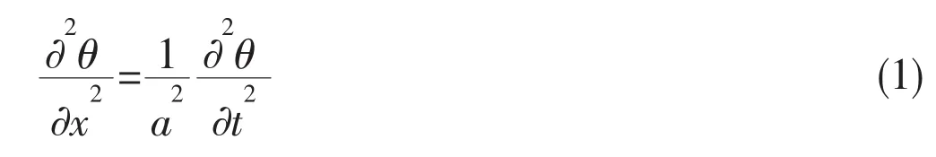
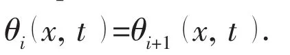
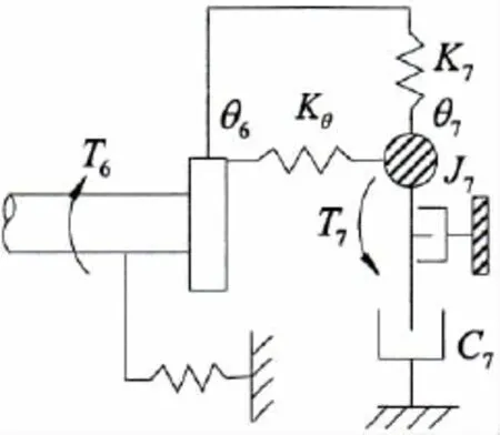
Fig.3 Flange connected with continuous and discrete sub-systems
For there is no propeller torque acted on the calculated shaft section,there is the equation

The shafting continuous and discrete sub-systems are connected directly with a flange, which is shown in the Fig.3.
For concentrated mass such as flanges,the equation can be obtained according to the equal corner of adjacent sections.To connect shafting continuous sub-system with diesel discrete sub-system,flange 6 is supposed to connect with the first diesel cylinder numbered 7. Based on the load condition,there is the following equation:

where Kθis torsional stiffness between the 1st diesel cylinder and connected flange,J7is the 1st cylinder moment of inertia.After θ7is obtained,the calculated internal elements of the diesel are dealt with traditional transfer matrix.
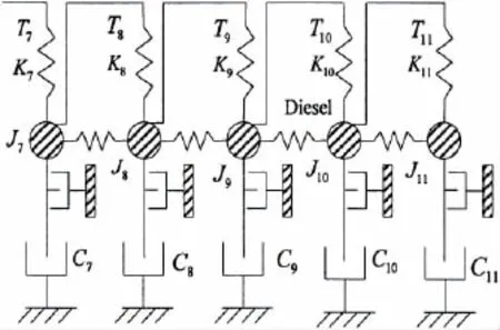
Fig.4 The discrete sub-system chart
The main engine is modeled as the discrete sub-system and each cylinder(together with its crank shaft and crank pin)or flywheel is treated as a concentrated mass[9].These discrete masses are connected end by end with torsional damped springs.Suppose the sub-systems consists of five concentrated masses whose parameters are shown in Fig.4.
Vibration equation in torsional direction is as follows:
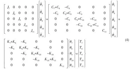
where T7,T8,T9,T10and T11are exciting torque acted on diesel cylinders.C7,C8,C9,C10and C11are damping of diesel cylinders.K7,K8,K9,K10and K11are stiffness of diesel cylinders. θ7,θ8,θ9,θ10and θ11are angular displacements of diesel cylinders.J7,J8,J9,J10and J11are diesel cylinder moment of inertia.
Based on wave approach,parameters on every calculated section are written in matrix as follows:


If the torsional shaft with length l,there are boundary conditionsT0at the extreme x=0 at t=0.
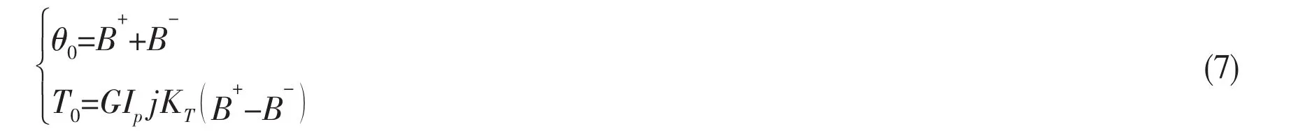
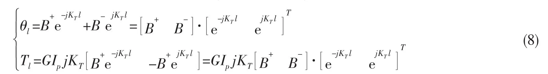
State vector relationship of shaft two extremes is solved.
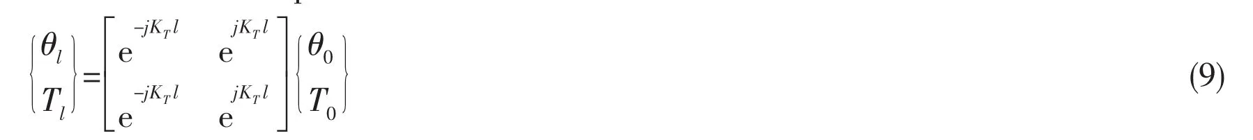
The transfer matrix is:
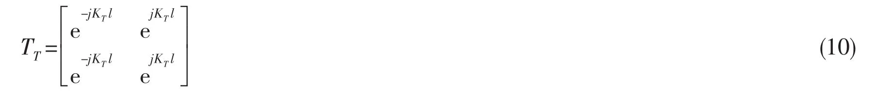
1.3 Transfer matrix of shafting torsional vibration
Based on above transfer matrix of torsional vibration,the transfer matrix of coupled vibration is established.The displacement vector of coupled vibration ismoment vector isthen
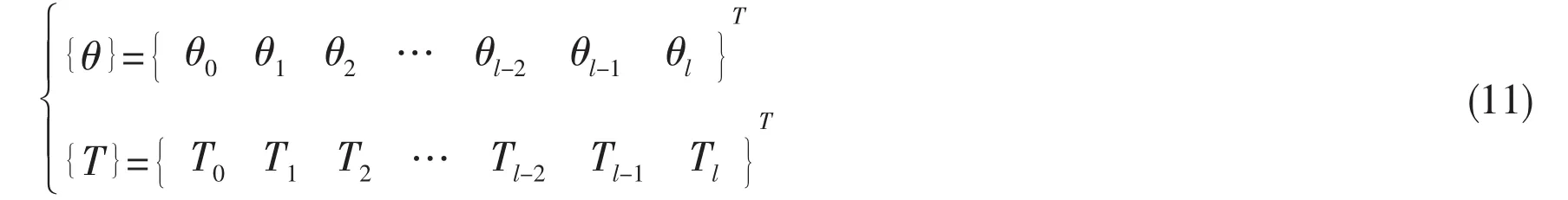
The transfer matrix of torsional vibration is expressed as follows:

The corresponding transmitting matrix is converted into the dynamic stiffness matrix.

where

1.4 Oil film stiffness of gearbox
The revolution of every substructure and gearbox is different.So the revolution of part shaft must be equivalent to a referenced shaft on the base of reality,then equivalent mass,rigidity and damp coefficient are calculated.One principle is that driven shafts are equivalent to driving shafts,and the other shafts are equivalent to main shafts.
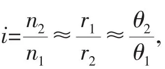
Traditional dealt method is that gears mesh with each other rigidly.The torques are Mdrivingand Mdriven,ndrivingor wdrivingis the revolution of driving shafts,ndrivenor wdrivenis the revolution of driven shafts,Ddrivingand Ddrivenare pitch diameters of driving and driven gears in Fig.5.
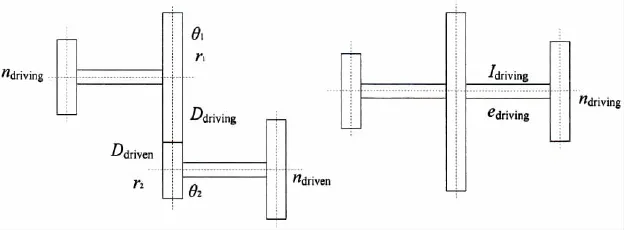
Fig.5 The conversion of the inertial system
Then there is the following formula:

By the law of energy conservation,the equivalent value of driven systems is calculated as follows:
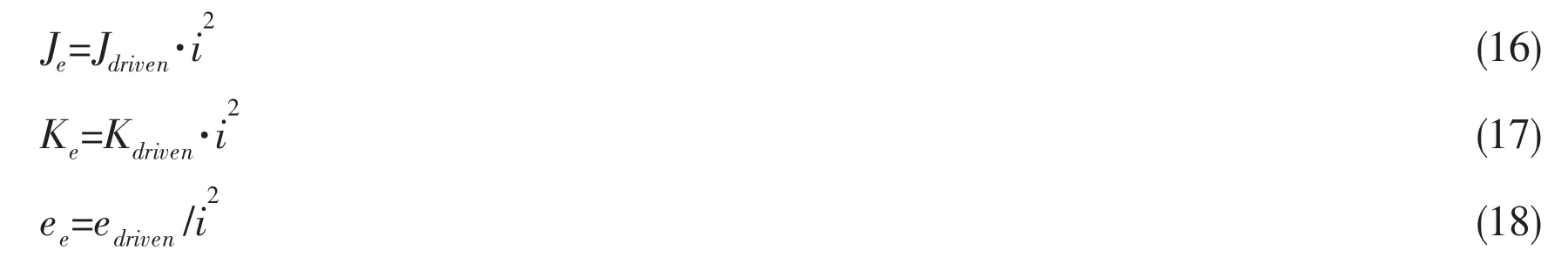
where Jdriven,Kdrivenand edrivenare the processional moment,rigidity and flexibility of driven shaft, respectively.And Je,Keand eeare the equivalent processional moment,equivalent rigidity and equivalent flexibility of the system,respectively.
Rotary inertia of components on driving and driven shafts is combined namely

As gears mesh,the influence of oil film stiffness is considered further more.The oil film stiffness on gearbox surfaces is modified as

where ΔF is load increment of oil film,and Δh is thickness change of oil film.The quality of oil film is neglected,kinetic equation of driven pulley is written as follows according to speed regulating system of gearboxes in Fig.5:
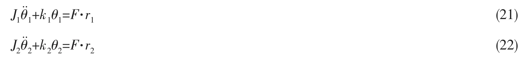

The formula is treated:

With oil film stiffness of gearboxes considered and compared Eq.(21)with Eq.(23),the rotating inertia and rigidity of driven shafts in speed regulating system are shown as follows:

2 Numerical investigations
The propulsive system of a certain LNG vessel consists of propeller shaft,reducing gearbox and diesel engine.It means that the traditional analysis method,which torsional vibration is calculated without oil film stiffness of gearbox,is not satisfied with shipbuilding development. Consequently,shafting torsional vibration of the vessel must be analyzed and re-calculated.The shafting arrangement and inertial numerical model of torsional vibration are shown in Fig.6.
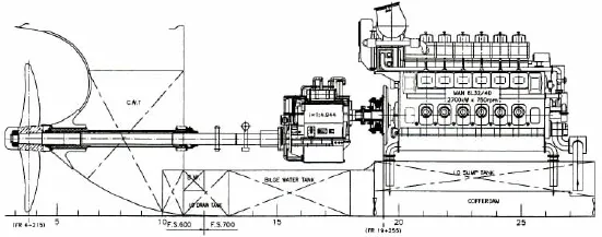
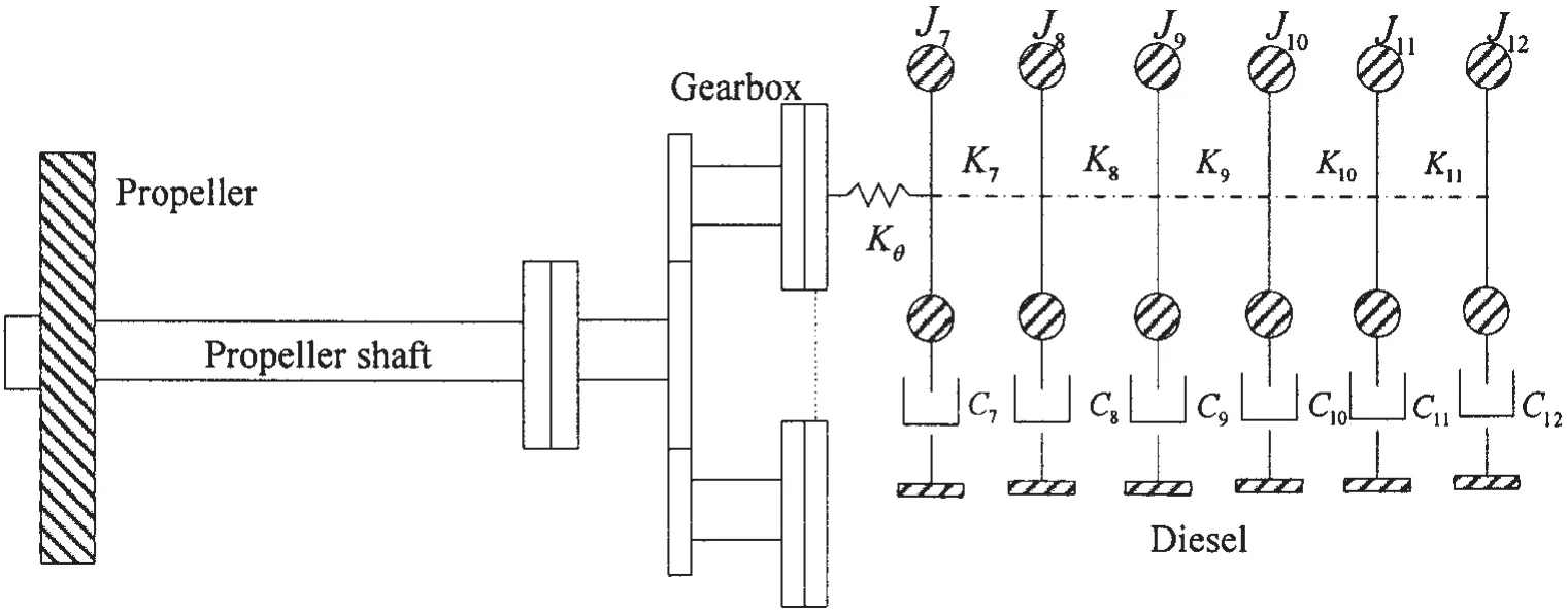
Fig.6 Shafting arrangement and inertial numerical model of torsional vibration for the LNG vessel
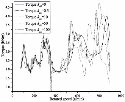
Fig.7 Torsional stress of propeller shaft at different rotated speed and oil film stiffness of gearbox
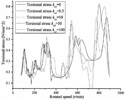
Fig.8 Torque of gearbox at different rotated speed and oil film stiffness of gearbox
Based on the vessel shafting and parameters,torsional stress of propeller shaft varies with the rotated speed in Fig.7.
According to the calculated results in Fig.7,the max torsional stress of propeller shaft varies in conditions of different oil film stiffness and rotated speeds.It influences the barred speed zone of propulsive shafting system.The max torsional stress takes place in lower rotated speed with oil film stiffness of gearbox ascending.The deviation to the lower speed zone is nearly 10%because of oil film stiffness.
In the same way,the torques of gearbox varies with rotated speed in the condition of different oil film stiffness in Fig.8.
Based on the relationship of oil film stiffness and gearbox torques in the Fig.8,the max gearbox torque varies under different oil film stiffness and rotated speeds.The max gearbox torque appears in lower rotated speed with oil film stiffness of gearbox ascending.The offset to the lower speed range is about 10%,it is not satisfied with the 10%deviation of barred-speed range permitted by the classification.
As the oil film stiffness of gearbox is satisfied with Reynolds equations,it is related to fluid density,viscosity,oil film thickness,and so on.Due to oil film stiffness existed between tooth surfaces of gearbox,the max torsional stress of propeller shaft and gearbox torque appear in the range of lower speed than that of situations where oil film stiffness is considered as rigid.
3 Conclusions
To most reducing gearboxes,they are lubricated by oil.There is oil film stiffness between tooth flanks of gearbox,the max torsional stress of propulsive shafts and gearbox torque take place in the range of much lower rotated speed,when the oil film stiffness is much greater in the tooth surfaces of gearbox.
The traditional method to analyze shafting torsional vibration,in which oil film stiffness of gearbox is neglected,is not applied to the development of shipbuilding technologies.For more accurate shafting vibration prediction on board,oil film stiffness should be measured and calculated in the process of shafting vibration analysis.Salutary lessons andReferencesare afforded to the vessel design and shipbuilding in the future.
[1]Wei Haijun.Modification of some formulas for calculating shaft torsional vibration[J].Journal of Vibration and Shock,2006, 25(2):166-167.
[2]Wang Hongzhi,Wei Haijun,Guan Delin,Chen Chunfang.Numerical simulation on ship shafting mechanics condition of intermediate bearing[J].Journal of Ship Mechanics,2006,10(1):98-105.
[3]Zhu Hanhua,Yan Xinping,Liu Zhenglin,Fan Shidong,Wen Sizhu.Research on impact response relationship between the rotating speed and lateral vibration[J].Journal of Wuhan University of Technology,2008,32(6):983-985.
[4]Li Hui,Zhou Ruiping.Research on the key points of torsional vibration of ship propulsion shafting[D].Wuhan University of Technology,2007,5.
[5]Bozca,Mehmet.Torsional vibration model based optimization of gearbox geometric design parameters to reduce rattle noise in an automotive transmission[J].Mechanism and Machine Theory,2010,45(11):1583-1598.
[6]Tang Bin,Song Xigeng.Study on the coupled torsional,axial and bending three-dimensional vibrations of internal engine shafting basing on exact dynamic stiffness matrix methods[D].Dalian University of Technology,2006.
[7]Tang Bin,Xue Dongxin,Song Xigeng.Study on dynamic matrix method for torsional vibration calculation of complex shafting[J].Ship Engineering,2003,25(3):24-26.
[8]Hsieh Shengchung,Chen Juhnhorng,Lee Anchen.A modified transfer matrix method for the coupling lateral and torsional vibrations of symmetric rotor-bearing systems[J].Journal of Sound and Vibration,2006,289:294-333.
[9]Zhang Zhihua.Numerical vibration calculation of machinery equipments[M].Harbin:Harbin Engineering University Press, 2007,10:87-100.
基于波分析法油膜剛度對軸系扭轉振動影響的研究
楊 勇1,2,車馳東1,唐文勇1
(1上海交通大學 海洋工程國家重點實驗室,上海200030;2中國船舶及海洋工程設計研究院,上海 200011)
為確保帶減速齒輪箱主推進系統的可靠性,文章對船舶軸系的扭轉振動進行了研究。首先根據各組成部件的特點將軸系分解為連續和離散的兩個子系統,分別利用波分析法和多自由度系統分析法列出連續子系統的波動形式及離散子系統的振動微分方程,同時考慮了減速齒輪箱油膜剛度的影響。然后根據兩子系統連接處的動態平衡和連續條件,建立整個軸系在扭轉振動模式下總運動方程,通過求解總方程得到系統的位移響應。該扭轉振動分析被應用到某LNG船帶減速齒輪箱的軸系振動計算中,通過考慮軸系減速齒輪箱嚙合齒面間油膜剛度使軸系扭轉振動模型更接近軸系實際運轉工況。計算結果顯示:隨著減速齒輪箱嚙合齒面間油膜剛度的增加,最大軸系扭轉應力向低轉速區域偏移。這對船舶軸系轉速禁區的劃分產生極大的影響。有助于防止因不良軸系振動計算引起軸系事故的發生。
軸系;扭轉振動;波分析;油膜剛度
U664.21
:A
楊 勇(1978-),男,上海交通大學船舶海洋與建筑工程學院博士研究生;中國船舶及海洋工程設計研究院輪機高級工程師;
U664.21
A
10.3969/j.issn.1007-7294.2015.09.010
1007-7294(2015)09-1139-10
車馳東(1980-),男,博士,上海交通大學船舶海洋與建筑工程學院講師,碩士生導師;
唐文勇(1970-),男,博士,上海交通大學船舶海洋與建筑工程學院教授,博士生導師。
Received date:2015-03-29
Foundation item:Supported by National Natural Science Foundation of China(No.51109131)
Biography:YANG Yong(1978-),male,Ph.D.student of School of Naval Architecture,Ocean and Civil Engineering, Shanghai Jiao Tong University,Machinery senior engineer MARIC,E-mail:konhitemi@163.com;
CHE Chi-dong(1980-),male,lecturer.
猜你喜歡
科學大眾(2023年17期)2023-10-26 07:39:14
艦船科學技術(2022年14期)2022-09-22 03:07:40
艦船科學技術(2022年8期)2022-06-05 07:36:28
艦船科學技術(2022年2期)2022-03-29 01:12:44
瘋狂英語·新讀寫(2020年3期)2020-06-06 09:05:56
小哥白尼(趣味科學)(2019年10期)2020-01-18 09:16:22
船舶標準化工程師(2019年4期)2019-07-24 07:21:12
中國公路(2017年18期)2018-01-23 03:00:38
數學物理學報(2017年6期)2018-01-22 02:26:40
中國船檢(2017年3期)2017-05-18 11:33:09

- 船舶力學的其它文章
- Study of Damping Ratio Identification for a Truss Spar Based on Continuous Wavelet Transform
- Study on Vortex Induced Characteristics of Four Square Columns at Different Spacing Ratio
- Roll Motion Prediction of PSV with Anti-rolling Tank Based on RANS and Nonlinear Dynamic Method
- Numerical Simulation of Strong Shock Wave Impacting on Water-elastic Solid Interface by Essentially Modified Ghost Fluid Method
- A Double-layer Depth-averaged Boussinesq Model for Water Wave
- Fatigue Strength Evaluation of Transverse Fillet Welded Joints Based on Notch Stress Strength Theory