Discussion on the Physical Significance of the Acoustic Target Strength of an Underwater Object in Shallow Water and Modal-Filtering Measurement
2015-05-01 22:23:08ZHANGBoZHANGXuegangMAZhongcheng
船舶力學 2015年3期
關鍵詞:實驗室
ZHANG Bo,ZHANG Xue-gang,MA Zhong-cheng
(1.Science and Technology on Underwater Test and Control Laboratory,Dalian 116013,China;2.University of Chinese Academy of Science,Beijing 100190,China;3.State Key Laboratory of Acoustics;Institute of Acoustics;Chinese Academy of Sciences,Beijing 100190,China)
Discussion on the Physical Significance of the Acoustic Target Strength of an Underwater Object in Shallow Water and Modal-Filtering Measurement
ZHANG Bo1,2,3,ZHANG Xue-gang1,MA Zhong-cheng1
(1.Science and Technology on Underwater Test and Control Laboratory,Dalian 116013,China;2.University of Chinese Academy of Science,Beijing 100190,China;3.State Key Laboratory of Acoustics;Institute of Acoustics;Chinese Academy of Sciences,Beijing 100190,China)
The acoustic target strength(TS)of an underwater platform is usually tested in shallow water.Utilizing normal mode theory,the analytical formula of the TS of an underwater object in shallow water is derived,based on the average-measurement method,and its physical significance is analyzed deeply.Analysis shows that,as for as a certain azimuth,TS is dependent on the target scattering function values at a few vertical incident angles,θm,and scattering angles,θn.θmand θnare discrete,their values depending on normal-mode order,m,n.Furthermore,TS is concerned with both the marine environment and the testing range,and it is approximately equal to the free-field target strength,TSfree,when the testing range is large enough.A new TS measurement method put forward,namely Modal-Filtering Measurement(MFM),based on a vertical source array and a vertical hydrophone array.According to theoretical analysis,MFM method performs well in both interface reverberation resistance and testing efficiency,compared with the average-measurement method and the classical vertical array method,its result is closer to TSfree.
shallow water;average-measurement method;acoustic target strength; modal-filtering;single mode
0 Introduction
At the present stage,the acoustic target strength(TS)of an underwater platform is usually tested in shallow water(SW).Direct method of measurement requires precise information of transmission losses,which is not practical in SW environment.Urick et al[1]put forward an indirect method of measurement-‘the transponder method’,which does not requires knowledge of transmission losses.However,transmission losses can not be‘removed’completely even if the transponder method is adopted,because of the unusually acoustic complexity of SW environment,which leads to high uncertainty of measurement.
In order to measure the TS of an underwater platform accurately,measures must be taken to eliminate the influence of sound-field spatial fluctuations on the testing results.Based on the transponder method,testing techniques which can be utilized are as follows:
(1)Measures repeatedly in different distances,and then take the average values.That is the Horizontal-Average Measurement(HAM).
(2)Measures repeatedly at different depths,and then take the average values.That is the Vertical-Average Measurement(VAM).
(3)Utilize a source/receiver array with directivity in the vertical plane to decrease interface interference and to reduce sound-field spatial fluctuations.In this paper,that is referred to as Classical Vertical Array Measurement(CVAM).
HAM is usually used because of its lower technical difficulty.VAM,by contrast,has higher technical difficulty,but it has higher testing efficiency and effectiveness.Both of them,with similar physical significance,are referred to as‘Average Methods’in this paper.CVAM is a complementary method,which is often applied together with HAM.More detailed characteristics about Average Methods can be found in Ref.[2].
Employing these techniques,‘the equal transmission losses condition’will be satisfied. Consequently,transmission losses will be‘removed’almost completely,and the testing accuracy is improved.However,what is the physical significance of the TS measured utilizing these techniques?And is it the same with the TS measured in free space?We have no answers to these questions yet.
The principle of the transponder method is briefly reviewed in Sec.1,followed by a normal-mode expression of TS in SW environment,based on Ingenito’s single-scattering-objectmodel[3-4]and VAM.Section 3 presents an analysis of the physical significance of the TS of an underwater platform in SW environment,which is measured utilizing Average Methods,and the differences between TS and TSfreeare analyzed.It indicates clearly that TS is approximately equal to TSfree,when the testing range is so large that only the first normal mode plays a leading role.However,the lager the testing range,the lower the signal-to-noise ratio(SNR).On this view,in Sec 4,a new measurement method is introduced,namely Modal-Filtering Measurement(MFM),which is based on a vertical transmitting array and a vertical receiving array,according to single-mode excitation theory[5-8]and modal-filtering theory[9-10].In Sec 5,MFM and the other methods are analyzed comparatively.Finally,we provide our concluding remarks in the last section.
1 Acoustic target strength and transponder method
Consider a plane wave incident on the target.TS is a measure of how much of the incident sound is scattered back in the direction of the sonar.TS is given by

According to the active sonar equation,TS can be written as

where EL is echo level,SL is source level,TL1is transmission loss from source to target,and TL2is transmission loss from target to source.Eq.(2)is the expression of TS measured by the direct method of measurement.Direct method of measurement requires precise information of transmission losses,which is not practical in SW environment.For that reason,Urick et al[1]put forward an indirect method of measurement-‘the transponder method’,which does not require knowledge of transmission losses.Fig.1 is a sketch map of the transponder method.TS measured by the transponder method is written as

where A=ELT-ELK.ELTis echo level of the target,ELKis pulse level of the transponder at receiver No.1,and K is the difference between pulse level of the transponder and incident sound level at receiver No.2.
The precondition of Eq.(3),namely‘the equal transmission losses condition’,is that the transmission losses from the source to each point in the volume occupied by the target are equal.In fact,however,this precondition can not be met perfectly in SW environment.So transmission losses can not be‘removed’completely even if the transponder method is adopted.
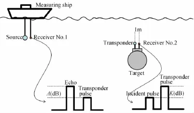
Fig.1 Sketch map of the transponder method
2 TS in SW environment
2.1 Target scattering sound field

Fig.2 Sketch map of target scattering in SW waveguide
With the lateral wave and multiple scattering between the target and the boundaries neglected,the acoustic field scattered by the target can be expressed in terms of normal modes and plane-wave scattering functions:
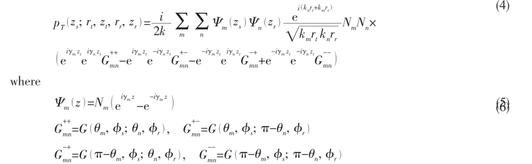

where θi(θs)is vertical incident(scattering)angle,and φi(φs)incident(scattering)azimuth angle.
In a monostatic context,considering Eq.(5)and its derivative,Eq.(4)will be simplified to

By Eq.(8),the scattering acoustic field of the target is expressed as the product of incident and scattering normal modes.H represents a mode-to-mode coupling matrix between the normal modes emitted by the source,Ψm(z),and the normal modes,Ψn(z),received by the receiver.
2.2 Acoustic target strength
According to Eq.(3),TS can be expressed as

From Eq.(8),we can obtain

where Θincis the incoherent component,and Θcohcoherent.

When an average method,e.g.VAM,is applied,the coherent component,〈Θcoh〉,becomes null.Then we obtain


Similarly,for the‘echo’of the transponder

where Q is the amplification factor of the transponder,K=20log10Q.If the transponder is omnidirectional,Smn=1,Eq.(15)becomes

Inserting Eq.(13)and Eq.(16)into Eq.(11),we get
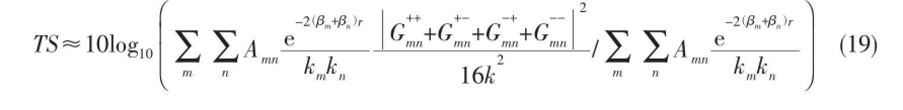
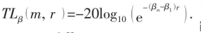
In the preceding derivation,the eigen-attenuation βmof normal modes is neglected.If it is taken into account,TS becomes

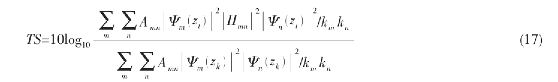
So far,we obtain the analytical expression of the acoustic target strength of an object in SW environment with VAM applied.According to the normal mode orthonormality condition,Eq.(18)can be simplified as
3 Physical significance of the acoustic TS in SW environment
According to Eq.(8),TSfreein a monostatic context is

where,the expression of TSfreeis given beforehand in order to be analyzed comparatively with TS in SW environment.
3.1 Physical significance

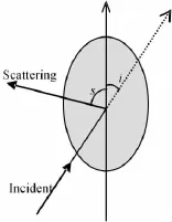
Fig.3 The geometry of incident and scattering angle

Fig.4 Relationship between TS and incident and scattering angles
According to Eq.(19),the value of TS in SW environment depends on the lower order modes more than on the higher order ones,because the lower order ones have smaller eigenattenuation βm.In addition,we know that θ=cos-1γm/()kand the vertical wave number γmisin direct proportion to the mode order,so it is clear that the higher the mode order,m or n, grows,the bigger the distance between Pmnand P0becomes.In consideration of the above two points,we draw a circular area on the θiθsplane in Fig.4(b),with deeper color in the center and lighter color all around.The color changing deeper means that the mode order becomes lower and the related values of G have greater influence on TS in SW environment.Furthermore,the larger the range r becomes,the lighter the color all around changes.That is to say,the larger the range becomes,the less influence the higher order modes have on TS in SW environment.
Ex1 A point source emits harmonic acoustic waves with time dependence e-iωt.H=100 m,c1=1 500 m/s,ρ1=1 g/cm3,c2=1 600 m/s,ρ2=1.8 g/cm3,α=0.3f1.8dB/m (f in units of kHz).All of the symbols mean the same as in Sec 2.1.
Considering the threshold value of TLβas 3 dB,the first 46,35,23 and 15 normal modes will play the dominate role on TS at a horizontal distance of 0.7,2,4 and 8 km,with a corresponding maximum grazing angle 20,15,10 and 7 degrees respectively.As for the target,the range of the corresponding vertical incident angle θi(scattering angle θs)is[70°,110°],[75°,105°],[80°,100°]and[83°,97°]respectively.For the sake of being more intuitive,we use‘degree’instead of‘radian’in units.In a word,the farther the distance,the smaller the number of the normal modes playing the dominate role.
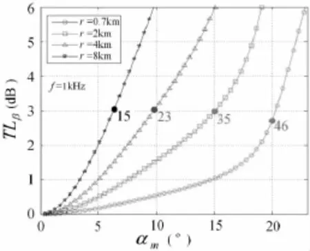
Fig.5 Simulated relationship between TLβand αmat 1 kHz.TLβis relative eigen-transmission-loss of normal modes,αmis grazing angle.
If the range becomes so large that only the first normal mode plays a leading role,Eq.(18) is simplified to

In the vertical plane,put the target and the transponder nearly at the wave loop of the first normal mode,then we have Ψ1(zt)≈Ψ1(zk).So we obtain

As for the first normal mode,it is clear that k1≈k and θ1≈π/2.According to Eq.(6),we have

Then Eq.(9)can be rewritten as

Inserted into Eq.(22),it is obtained that

Eq.(25)indicates clearly that TS in SW environment is approximately equal to TSfree(π/2,π/2),when the range becomes so large that only the first normal mode plays a leading role.
Note that it is impractical to try to acquire a TS approaching TSfree(π/2,π/2)by means of increasing the testing distance continually,because SNR of echo decreases with the testing distance.For that reason,we will introduce a testing method only utilizing the first normal mode, namely Modal-Filtering Measurement(MFM),in Sec 4.
3.2 Simulation analysis of TS in SW environment
In the context of Ex1,we analyze the difference between TS in SW environment and TSfree(π/2,π/2),with frequency 100 Hz-5 kHz and distance 700 m-100 km.In order to compare the influence of different scattering functions G on TS,we consider three different targets:a 10 m-radius rigid sphere,Target No.1 and Target No.2,with scattering functions Gsphere,G1and G2respectively.The expression of Gsphereis[3]

According to Lambert scattering model,we define G1and G2as:
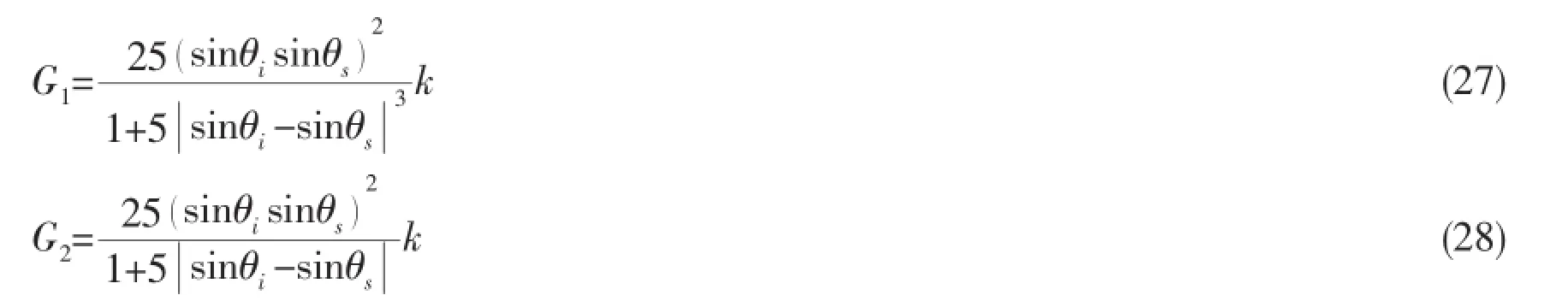
In the coordinate system of Fig.4,Gsphere,G1and G2are symmetrical about the line θi=θsand the line θi+θs=π.The associated values of TSfreeare shown in Fig.6.
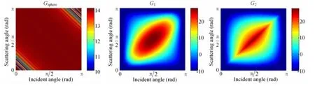
Fig.6 The values of TSfreeof the rigid sphere,Target No.1 and Target No.2

δTS is the difference of TS and TSfree,defined asThe relationship between δTS and horizontal distance,r,is illustrated in Fig.7,at 1 kHz.It is clear that δTS approaches 0 dB with r growing,that is,TS approaches TSfree(π/2,π/2).That agrees with the analysis in Sec 3.1.

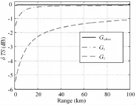
Fig.7 Relationship between δTS and r,f=1 kHz
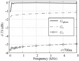
Fig.8 Relationship between δTS and f,r=700 m
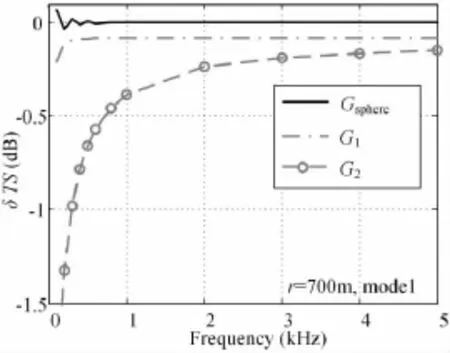
Fig.9 Relationship between δTS and f, when only the first normal mode is considered,r=700 m
When only the first normal mode is considered, the relationship between δTS and f is shown in Fig.9. Compared with Fig.8,it is clear that the results in Fig.9 are much better.
4 Modal-Filtering Measurement(MFM)
4.1 Single mode excitation[5-8]
The environmental conditions are the same in Fig.2.For a harmonic point source at the origin at depth z0,the pressure field in the far field at the point r,z can be expressed as

with the lateral waves neglected,where

The normal-mode eigenfunctions Ψm(z)form a complete orthonormal set satisfying the orthonormality relation


where the set of coefficients wlare the weighting coefficients for each of the L sources in the source array.Let the weighting coefficients be defined by the eigenfunction of the first mode sampled at the source depths,that is

In that context,the pressure field at the point(r,z)due to the weighted source array is given by

For L sufficiently large,by the mode orthonormality condition of Eq.(32),it would be expected that

for our constant density assumption.As a result

Eq.(37)indicates that only the first normal mode exists in the sound field emitted by an L-element source array weighted by the eigenfunction of the first mode.In that case,the pressure field varies slowly with r and z,considering Eq.(31)and(37).
4.2 Modal filtering[9-10]


according to the acoustic reciprocity theorem.
4.3 TS Measured by MFM
By the analysis in Secs 4.1 and 4.2,we know that only the factors of the first normal mode remain in the expression,Eq.(18),of TS in SW environment,when both the vertical source array and the vertical receiver array are weighted by the eigenfunction of the first mode.Furthermore,considering the analysis in Sec 3,we obtain

where TSMFis the target strength measured by MFM,which is the same as TS expressed by Eq.(25)for r sufficiently large.Both of them are approximately equal to TSfree(π/2,π/2).
Although both MFM and Average Methods,such as HAM and VAM,are based on the transponder method,they are quite different.HAM or VAM requires averaging the results measured repeatedly in different distances or at different depths,in order to satisfy‘the equal transmission losses condition’.However,applying MFM,only the factor,S1,associated with the first normal mode remains in the sound field emitted by the weighted vertical source array and in the output of the weighted vertical receiver array,while S1varies slowly with r and z. Consequently,‘the equal transmission losses condition’is satisfied naturally,and then repeated measurements are not required.

4.4 MFM’s resistance to interface reverberation
Interface reverberation is one of the main interferences in SW TS measurement.And a higher signal-to-reverberation ratio(SRR)helps to improve the testing accuracy.
Firstly,we consider the bottom reverberation.By the ray-normal-mode incoherent reverberation theory in shallow water[12-13],the reverberation of a receiver at(0,zr)can be written as

with the point source at(0,zs),where N is the number of bottom scatters per unit area,E0is the energy emitted by the source,and Iiis the scattering intensity of a single scatter.The operator,〈〈〉〉,means statistical average,and

where

where σ( αm,αn)is the scattering function,αmis the grazing angle of the mth mode at bottom, and Bmis the amplitude of the downward quasi-plane wave associated with the the mth mode at the bottom.
For a monostatic context,applying MFM,〈〈Ii〉〉is simplified to

because only the factor associated with the first normal mode remains in the sound field emitted by the weighted vertical source array and in the output of the weighted vertical receiver array.
Usually,σ( αm,αn)is a decreasing function for αmand αn,e.g.,the Lambert scattering model

So we obtain

The above analysis is also suitable for surface reverberation.In a word,MFM has great resistance to interface reverberation.
4.5 Element spacing of the vertical array
The precondition of applying MFM effectively is that Eq.(36)is satisfied,so that the vertical space-sampling frequency,1/d,must be equal or greater than the Nyquist frequency,

where d is the element spacing of the vertical array,and λzM=2π/γM,γMis the vertical wavenumber of the highest order normal mode.Because γMis always smaller than k,we have

Inserting Eq.(47)into Eq.(46),we have

As for the vertical receiver array,ambient noise should be taken into account.Considering isotropic noise,the element spacing,d,should satisfy

According to Eq.(48)and Eq.(49),a reasonable value of the element spacing is

5 MFM compared with other methods
5.1 Compared with CVAM
When the Classical Vertical Array Measurement(CVAM)is applied,the sound field emitted by a vertical source array is written as

For comparison with Eq.(37),we define


By the acoustic reciprocity theorem,the output of a vertical receiver array can be written as

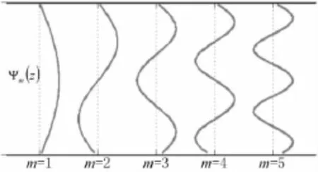
Fig.10 The first 5 eigenfunctions
when CVAM is applied.
To sum up,we can draw a conclusion from Eqs.(36),(37),(53)and(54)that MFM results in smaller and slower sound-field spatial fluctuations compared with CVAM,for both soundemitting and sound-receiving process.In addition,CVAM is a complementary method,which is often utilized together with HAM,while MFM can be used separately.
5.2 Compared with average methods
MFM,Average Methods,such as HAM and VAM,and CVAM are all based on the transponder method.That is the common points of them.
Average Methods require repeated measurements in different distances or at different depths,and then averaging the results.By contrast,MFM does not require averaging repeated measurements,so it has a higher testing efficiency.Furthermore,the target strength,TSMF, measured by MFM is closer to TSfree(π/2,π/2)than TS measured by Average Methods.
6 Concluding remarks

A new measurement method is introduced,namely Modal-Filtering Measurement(MFM), which is based on a vertical source array and a vertical receiver array,according to singlemode excitation theory and modal-filtering theory.According to theoretical analysis,MFM performs well in both interface reverberation resistance and testing efficiency,compared to Average Methods and CVAM,and what is more,its result is closer to TSfree.
However,MFM requires deploying both a vertical source array and a vertical receiver array,with the array length,L,equal to the thickness of water column,H.Moreover,environmental parameters,such as seawater sound-speed profile,and sound speed,density and attenuation coefficient of the seabed,are required.These are the shortcomings of MFM.
[1]Urick R J.Principles of underwater sound[M].NewYork:McGraw-Hill,1975:241-243.
[2]Zhang Bo,Ma Zhongcheng,Song Man.Theoretical analyses of measurement of the acoustic target strength of underwater platform using the transponder method in shallow water[J].Applied Acoustics,2013,32(2):109-115.(in Chinese)
[3]Ingenito F.Scattering from an object in a stratified medium[J].J Acoust.Soc.Am.,1987,82(6):2051-2059.
[4]Yang T C,Yates T W.Scattering from an object in a stratified medium:Freqency dispersion and active localization[J].J Acoust.Soc.Am.,1994,96(2):1003-1019.
[5]Williams A O,Novak B M.Normal mode analysis of underwater sound propagation with directional sources and receivers [J].J Acoust.Soc.Am.,1974,55(1):80-83.
[6]Gazanhes C,Garnier J L.Experiments on single mode excitation in shallow water propagation[J].J Acoust.Soc.Am.,1981, 69(4):963-969.
[7]Gingras D F.Single mode excitation,attenuation,and backscatter in shallow water[J].J Acoust.Soc.Am.,1998,103(1): 195-204.
[8]Peng Dayong,Zeng Juan,Li Haifeng,et al.An optimal algorithm for single-mode close-loop excitation in shallow water [J].Chinese Journal of Acoustics,2009,34(5):396-400.
[9]Shang E C.Source depth estimation in waveguide[J].J Acoust.Soc.Am.,1985,77(4):1413-1418.
[10]Shang E.C,Clay C,Wang Y.Passive harmonic source ranging in waveguides by using mode filter[J].J Acoust.Soc.Am., 1985,78(1):172-175.
[11]He Zuoyong,Zhao Yufang.Theoretic fundamentals of acoustics[M].Beijing:National Defence Industry Press,1981:315-322.(in Chinese)
[12]Zhang Renhe,Jin Guoliang.Normal mode theory of the average reverberation intensity in shallow water[J].Chinese Journal of Acoustics,1984,9(1):12-20.(in Chinese)
[13]Li Fenghua,Liu Jianjun,Li Zhenglin,et al.The oscillation phenomena of low-frequency reverberation in shallow water and its physical interpretation[J].Science in China G,2005,35(2):140-148.(in Chinese)
淺海環境中水下物體聲目標強度物理意義的討論及模式濾波測量法
張波1,2,3,張學剛1,馬忠成1
(1水下測控技術重點實驗室,大連116013;2中國科學院大學,北京100190;3中國科學院聲學所聲場聲信息國家重點實驗室,北京100190)
水下運動平臺的聲目標強度測量試驗多在淺海環境中進行。文章根據簡正波理論推導了基于平均測量法的淺海環境中水下物體聲目標強度TS的解析表達式,深入分析了TS的物理意義。分析表明,在確定的方位角上,TS與分布在一定范圍內的垂直入射角θi和散射角θs所對應的目標散射函數值有關,θi和θs是離散的,其取值取決于簡正波階數;同時,TS還跟海洋環境和測試距離有關,當測試距離非常大時,約等于自由場聲目標強度TSfree。文中還提出了一種基于垂直發射陣和垂直接收陣的聲目標強度測量方法,即模式濾波測量法(Modal-Filtering Measurement,MFM)。理論分析表明,MFM法具有很好的抗界面混響性能,并且跟平均測量法和垂直陣常規測量法相比,具有更高的測試效率,測試結果更接近自由場聲目標強度。
淺海;平均測量法;聲目標強度;模式濾波;單模
O427
:A
張波(1982-),男,水下測控技術重點實驗室工程師;
1007-7294(2015)03-0322-15
O427
:A
10.3969/j.issn.1007-7294.2015.03.010
張學剛(1980-),男,水下測控技術重點實驗室高級工程師;
馬忠成(1966-),男,水下測控技術重點實驗室研究員。
Received date:2014-07-09
Foundation item:Supported by the Advance Research Project(51303030408)
Biography:ZHANG Bo(1982-),male,engineer,E-mail:popo6189@163.com;
ZHANG Xue-gang(1980-),male,senior engineer.
猜你喜歡
電子競技(2020年8期)2020-12-23 04:09:40
電子競技(2020年7期)2020-10-12 10:45:48
電子競技(2020年5期)2020-08-10 08:43:10
電子競技(2020年4期)2020-07-13 09:18:06
電子競技(2020年2期)2020-04-14 04:40:38
電子競技(2020年11期)2020-02-07 02:49:36
電子競技(2020年9期)2020-01-11 01:06:21
電子競技(2020年10期)2020-01-11 01:06:06
電子競技(2019年22期)2019-03-07 05:17:26
電子競技(2019年21期)2019-02-24 06:55:52

- 船舶力學的其它文章
- CFD Computation of Added Resistance for KVLCC2 Model in Head Short Waves
- Stress Field Analysis of 135-degree Sharp Corners Based on Notch Stress Strength Theory
- Review on Advances in Research of Ice Loads on Ice-going Ships
- Identification Method for Exciting Force Source Inside Underwater Structure Based on PSO_GA
- Vibration Response Analysis of an Underwater Submersible
- Research on Numerical Simulation of Ship-ice Collision Based on MD Nastran