Autonomous map query: robust visual localization in urban environments using Multilayer Feature Graph*
2015-02-15 02:19:18LiHaifeng李海豐WangHongpengLiuJingtai
High Technology Letters 2015年1期
Li Haifeng (李海豐), Wang Hongpeng, Liu Jingtai
(*College of Computer Science and Technology, Civil Aviation University of China, Tianjin 300300, P.R.China)(**Insititute of Robotics and Automatic Information System, Nankai University, Tianjin 300071, P.R.China)
?
Autonomous map query: robust visual localization in urban environments using Multilayer Feature Graph*
Li Haifeng (李海豐)*, Wang Hongpeng***, Liu Jingtai**
(*College of Computer Science and Technology, Civil Aviation University of China, Tianjin 300300, P.R.China)(**Insititute of Robotics and Automatic Information System, Nankai University, Tianjin 300071, P.R.China)
When a vehicle travels in urban areas, onboard global positioning system (GPS) signals may be obstructed by high-rise buildings and thereby cannot provide accurate positions. It is proposed to perform localization by registering ground images to a 2D building boundary map which is generated from aerial images. Multilayer feature graphs (MFG) is employed to model building facades from the ground images. MFG was reported in the previous work to facilitate the robot scene understanding in urban areas. By constructing MFG, the 2D/3D positions of features can be obtained, including line segments, ideal lines, and all primary vertical planes. Finally, a voting-based feature weighted localization method is developed based on MFGs and the 2D building boundary map. The proposed method has been implemented and validated in physical experiments. In the proposed experiments, the algorithm has achieved an overall localization accuracy of 2.2m, which is better than commercial GPS working in open environments.
visual localization, urban environment, multilayer feature graph(MFG), voting-based method
0 Introduction
Localization is a key component in many mobile robot applications. GPS is popularly used for location-awareness. However the measurement error of low-cost GPS sensors for civil services may be up to tens of meters. Especially when working in an urban area, the GPS signal may be disrupted by high-rise buildings and becomes more unreliable. When a mobile robot equipped with a GPS sensor is traveling in urban environments, it can only obtain the inaccurate GPS data, which can only provide the robot with a rough location region in the 2D map, as shown in Fig.1, where the dashed circle represents the potential location region obtained from inaccurate GPS data, triangleAin Fig.1(b) from multi-pair of camera frames taken at two different locations ofAandBin succession, given the inaccurate GPS data and a 2D top-down view building boundary map which is extracted from Google Maps in our experiments. Thus, it is needed to further determine the accurate location of robotAwith the aid of other sensors. As cameras become small and cheap, the focus in this work is to develop an accurate visual localization method for mobile robots working in urban environments.
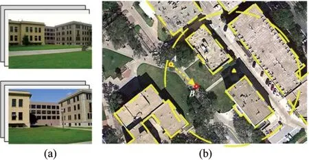
Fig.1 Estimating camera location
Ref.[1] reported MFG to facilitate the robot scene understanding in urban area. MFG also connects the features in two views and the corresponding 3D coordinate system. An MFG is constructed from overlapping and dislocated two views and contains five different features ranging from raw key points to planes and vanishing points in 3D. By constructing MFG, the 2D/3D positions of features can be obtained including line segments, ideal lines, and all primary vertical planes.
It is an immediate application to employ MFG for localization applications. In this paper, MFG is applied to robot localization, given a 2D map with building outlines in top-down view with no 3D geometric information or appearance data. The 2D building outline map is extracted from Google Maps in our experiments. The proposed method has been implemented and validated in physical experiments. The localization error of the proposed algorithm in physical experiments is around 2m.
1 Related work
Visual localization[2,3]utilizes images taken from on-board camera(s) to estimate the robot location. The ability of accurate localization is an essential building block of robot navigation[4]and simultaneous localization and mapping (SLAM)[5].
Visual localization can have different camera configurations including omnidirectional camera and stereo vision systems. In Ref.[6], a fast indoor SLAM method using vertical lines from an omnidirectional camera was proposed. Nister et al. developed a visual odometry system to estimate the ego-motion of a stereo head[7]. In the proposed method, a regular pinhole camera is employed.
A way of classifying visual localization methods is based on what kinds of features are used. Point features, such as Harris corners, scale invariant feature translation (SIFT)[8], and speed up robust feature (SURF) points[9]are the most popular and reliable ones. Many researchers developed their point feature-based visual localization methods[10,11]. However, compared with line features, point features usually contain more noise and result in high computation cost due to their large amount. Line features are easy to extract[12]more robust, and insensitive to lighting condition or shadows. Therefore, many visual localization applications employed line features and achieved quite accurate results[13-15]. Several recent works[16,17]reconstructed building facades to localize robots in urban scenes. Delmerico[18]proposed a method to determine a set of candidate planes by sampling and clustering points from stereo images with random sample consensus (RANSAC), using local normal estimates derived from principal component analysis (PCA) to inform the planar model. This method is a point-based method whose shortcomings have been discussed above. Cham[17]tried to identify vertical corner edges of buildings as well as the neighboring plane normals from a single ground-view omnidirectional image to estimate the camera pose from a 2D plan-view building outline map. However, this method is not robust for plane analysis due to missing vertical hypotheses. Those methods provide the inspiration that planes are important and robust features to be extracted in reconstruction and localization. Furthermore, a very recent work[18]developed a footprint orientation (FPO) descriptor, which is computed from an omnidirectional image, to match in 2D urban terrain model that is generated from aerial imagery to estimate the position and orientation of a camera.
A number of papers have addressed the problem of matching ground view images to aerial images[19], but they assume that 3D models in the aerial image are available, and focus on specific buildings rather than a broad search across the entire aerial image. Tracking using line correspondences between ground view video and an aerial image was carried out in Ref.[3].
The research group has worked on robot navigation using passive vision system in past years. A vertical line-based method for visual localization tasks[15]has been developed. In recent work[1], an multilayer feature graph (MFG) was reported to facilitate the robot scene understanding in urban area. Nodes of an MFG are features such as SIFT feature points, line segments, lines, and planes while edges of the MFG represented different geometric relationships such as adjacency, parallelism, collinearity, and coplanarity. MFG also connects the features in two views and the corresponding 3D coordinate system. The localization method based on MFGs will be shown.
2 System architecture and problem definition
2.1 System architecture and assumptions
Fig.2 illustrates the system architecture. The proposed approach consists of off-line map generation and on-line robot localization. There are two main steps in off-line map generation: (1) Extracting an aerial image where the robot locates from the aerial image database based on the inaccurate GPS data, and (2) Generating a 2D map from the aerial image. On-line robot localization consists of three main steps: (1) Constructing MFG from each pair of overlapped camera images; (2) Conducting the perspective projection to obtain the 2D building facade outlines with line features on them from the top-down view; and (3) Estimating the robot location using a voting-based method based on the 2D map and the MFGs after perspective projection. These steps are illustrated in Fig.2 and each step is described in detail in the following sections.
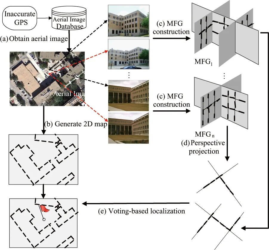
Fig.2 System architecture
To formulate the problem and focus on the most relevant issues, the following assumptions are developed.
? The 2D map is up-to-date.
? The intrinsic parameters of the finite perspective camera are known by pre-calibration. The lens distortion has been removed.
? The robot knows its relative movements between places where two views are taken, which can be achieved with on-board inertial sensors or wheel encoders. These sensors are good at short distance measurement. This assumption is for the construction of MFG.
2.2 Problem definition
In this paper, all the coordinate systems are right hand systems. The superscript denotes the corresponding notation in the second view. For example, notations in the format of (a,a′)refertoapairofcorrespondingfeaturesacrosstwoviews.
?Define{W}asa3DCartesianworldcoordinatesystem(WCS)withitsx-zplanehorizontalandy-axispointingupwards.
?Define{C}and{C′}astwo3DCartesiancameracoordinatesystems(CCS)atthefirstandsecondviews,respectively.ForeachCCS,itsoriginisatthecameraopticalcenter,itsz-axiscoincideswiththeopticalaxisandpointstotheforwarddirectionofthecamera,itsx-axisandy-axisareparalleltothehorizontalandverticaldirectionsoftheCCDsensorplane,respectively.
?Define{I}and{I′}astwo2Dimagecoordinatesystems(ICS)atthefirstandsecondviews,respectively.ForeachICS,itsoriginisattheprincipalpointanditsu-axisandv-axisareparalleltoxandyaxesof{C},respectively.

? DefineXas the estimated robot location in {W}whentakingF.DenoteX=[x,z]T, where (x,z)istherobotlocationonthex-zplaneof{W}.
Withthesenotationsdefined,definitionisthefollowing.
Definition 1. MFG-based Localization: GivenFandF′,theinaccurateGPSdataanda2Dbuildingboundarymapfromtop-downview,constructMFGstoestimateX.
3 Approach
3.1 Aerial image extraction and map generation
The publicly available Google Maps are chosen as the proposed aerial image database. Based on the GPS data, it can be easily to obtain the aerial image where the robot locates from the database.

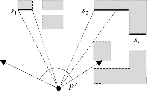
Fig.3 Visibility of building facades in a 2D map
3.2 Multilayer feature graph construction
Since the proposed visual localization algorithm is based on MFGs, it will be to start with a brief review of MFG, which was firstly presented in the previous work[1]. Fig.4 illustrates how MFG organizes different types of features according to their geometric relationships. MFG is a data structure consisting of five layers of features, i.e., key points, line segments, ideal lines, vertical planes and vanishing points. Edges between nodes of different layers represent geometric relationships such as adjacency, collinearity, coplanarity, and parallelism. MFG also connects the features in two views and the corresponding 3D coordinate system.
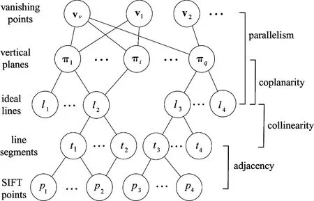
Fig.4 The structure of an MFG
In an MFG, key points and line segments are raw features extracted from images using methods like SIFT[8]and line segment detector (LSD)[12], while other layers of features are estimated based on them. In Ref.[1], a feature fusion algorithm is presented to construct an MFG based on two views by verifying the geometric relationships incrementally, iteratively, and extensively. As an important part of MFG, the algorithm is able to detect all primary vertical planes and line features in them with a reasonable accuracy. In this work, the localization application using MFGs will be focused on.
3.3 Perspective projection
Since the building boundary map obtained from the aerial image is a 2D map, it also needs to project MFGs to the 2D ground plane to prepare for the following matching. The vertical planes in MFG are parallel toy-axisin{W} (andthereforealsothegroundplanenormal),thus,theproblemreducestoa1Dperspectiveprojection.

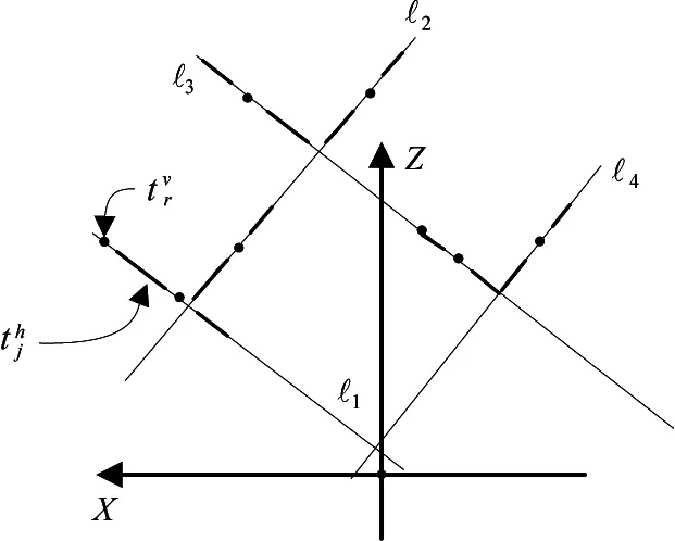
Fig.5 Perspective projection of an MFG
3.4 Feature-weighted localization using a single MFG
After the perspective projection step, the localization problem using a single MFG converts into matchingPintoMtofindtheaccuratecameralocationX.

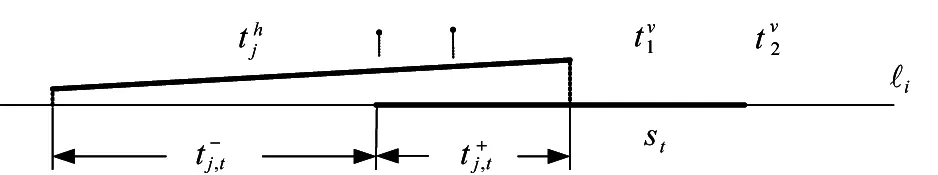
Fig.6 An illustration of matching evaluation
(1)

(2)
l+is defined as an index set for li∈Psuch that ?i∈l+, lihas at least one correspondence inMh.Similarly, l-is defined as an index set for lj∈Psuch that ?j∈l-, ljhas no correspondence inM.

(3)

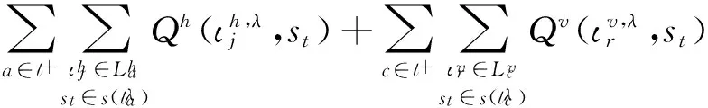
In Eq.(3), the first two terms are to evaluate the overlapping between horizontal/vertical line segments inPandbuildingboundariesinM,andthelasttermistodemonstratethecasethatthereisnobuildingboundaryinMcorrespondingtoverticalplaneπb.
Therefore,thelocalizationproblemusingasingleMFGbasedonthemapquerycanbeconvertedintothefollowingoptimizationproblem,
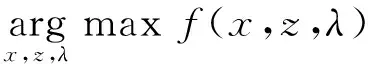
(4)
TheaboveoptimizationproblemcanbesolvedusingtheLevenberg-Marquardtalgorithm[21].
Bynow,thecameralocationcanbeobtainedfromanMFGanda2Dbuildingboundarymapbysolvingtheaboveoptimizationproblem.However,thismethodcannotguaranteethecorrectnessofsolution.Inthe2DbuildingboundarymapM,ifthereexistmorethanonegroupofsimilarbuildingboundariesthatcanmatchwithP,maximizingEq.(4)directlymayleadtothewrongsolution.ThecasewillhappenmorelikelywhenthenumberofverticalplanesinPissmall.Tosolvethisproblem,avoting-basedcamerapositionestimationmethodisproposedasfollows.
3.5Voting-basedlocalizationusingmultipleMFGs
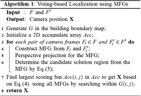
Inthevoting-basedlocalizationstage,first,the2DbuildingboundarymapisdividedintoaNa×NagridGanddefineazero-initializedNa×NaaccumulatorarrayAcccorrespondingly.Denote(xi,zj)asthecenterofG(i,j).Intheproposedvoting-basedmethod,eachMFGdoesnotonlydetermineonesolutionfromEq.(4).Instead,eachMFGcanprovidemultiplecandidatesolutions.TraverseG,andsetG(i,j)asacandidatesolutionregionif
(5)
wherefmaxisthemaximumvalueobtainedfromEq.(4),Trisaspecificratiothreshold,and
Correspondingly,Acc(i,j)incrementsby1ifG(i,j)isselectedtobeacandidatesolutionregion.Inordertoobtainthecorrectandoptimalcameraposition,thecombinationofcandidatesolutionswiththebestconsensusobtainedfromdifferentMFGsmustbedetermined.Thus,thecandidatesolutionregionwiththelargestscore(numberinAcc)isselectedasthecorrectsolutionregion.ThefinaloptimalsolutionisdeterminedbasedonEq.(4),andtheonlydifferenceisthatmultipleMFGsareutilizedhereandthesearchingregioniswithinthesub-regionwiththelargestscore.
Theproposedvoting-basedcamerapositionestimationmethodusingmultipleMFGsisdescribedasAlgorithm1.
4 Experiments
The proposed visual localization method has been implemented by using Matlab 2008b on a laptop PC. In the physical experiments, a BenQ DCE1035 camera with a resolution of 1095×821 pixels is used. It is to run 7 tests (Ai,Bi),i=1,…,7onauniversitycampus,asshowninFig.7,wherepointsAi,i=1,…,7denotethefirstpositionsineachtesttotakepictures,respectively,andpointsBi,i=1,…,7arethesecondpositionstocapturepictures,respectively.Forthefivetests(A1,B1)-(A5,B5), 4pairsofcameraframesaretakenwithsignificantoverlappingineachtest.Fortheothertwotests(A6,B6)and(A7,B7), 3pairsofcameraframesaretakenineachtest.Thebaselinedistancebetweentwopositionsineachtestismeasuredwithatapemeasure.Theorientationsettingsofthecameraaresettoensureagoodoverlappingbetweeneachpairofimages.Inordertodeterminethegroundtruthofcamerapositions,therelativedistancesfromthecameracentertothesurroundingbuildingfacadesaremeasuredusingaBOSCHGLR225laserdistancemeasurerwitharangeupto70mandmeasurementaccuracyof±1.5mm.ConsideringthelocalizationerrorofGPSinurbanenvironments,thewholesearchingregionissettobe150m×150m,centeredatGPSdata.Gissettobe60×60,withthesizeofeachsub-regionbeing2.5m×2.5m.ThresholdTrissettobe0.7.

Fig.7 Positions and orientations of camera in 7 tests
4.1 MFG construction results

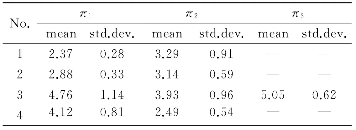
Table 1 Percentile relative errors of the reconstructed 3D points
Table 1 gives a sample output where the MFG construction algorithm has identified vertical planes in the images, which results in the different numbers of vertical planes for the image pairs in test (A1,B1).Therelativeerrorsofpointsonplanesarereasonablysmallwhichindicatesthattheestimatedplanesarereasonablyaccurate.
4.2Voting-basedlocalizationresults
Toinformallyevaluatetheeffectivenessofourvoting-basedlocalizationmethod,solutionuniquenessisinspectedbyvisualizingscoresina2Drobot-positionversionoftheaccumulatorarray.AnexampleresultisshowninFig.8.Givenonlyonebinwiththehighestscore,itisevidentthatfinalsolutionisunique.
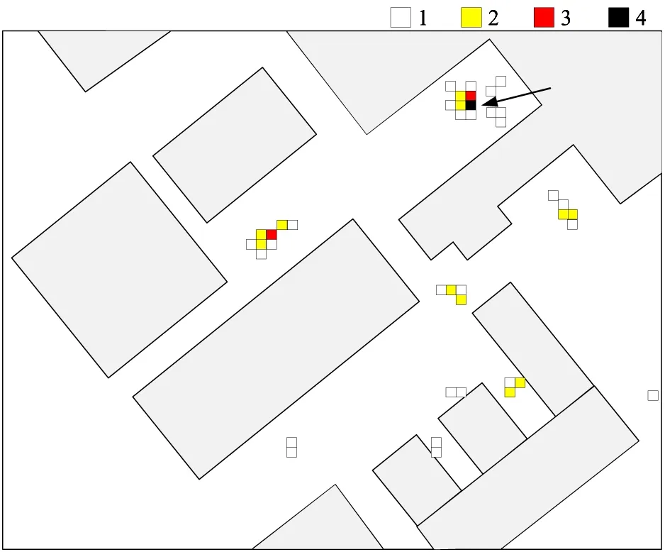
Fig.8 Example distribution of camera position scores in a 2D position version of the accumulator array, with 2D map overlay. Arrow shows ground truth position.
The MFG-based localization method is compared with the line-based method[15]. Table 2 shows the localization errors using the two methods, respectively. From the table we can conclude that, both methods can localize the camera correctly in all tests. The localization errors of the MFG-based method are obviously smaller than those of line-based method. And in comparison with the ground truth, all the localization errors using the proposed MFG-based method are no more than 2.8m, and the average error is 2.2m. This result is superior to that of the standard positioning service by GPS. The localization error is caused by many factors, such as MFG construction error and map generation error.
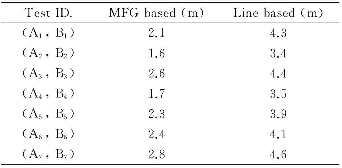
Table 2 Comparison of localization errors between MFG-based and line-based methods
5 Conclusions
A robust visual localization method is reported based on MFGs and a 2D top-down view building boundary map. By constructing MFGs from camera frames, the 2D/3D positions of multiple features, including line segments, ideal lines, and all primary vertical planes are obtained. A voting-based map query method has been proposed to find the accurate location of camera in the 2D map. The localization method has been implementedand tested in the physical experiments. Results showed that the localization error of the proposed method is around 2m, which is better than commercial GPS working in open environments. More experiments will be done in the following, and it is also planed to integrate the proposed approach with other localization methods and sensors.
[1] Li H F, Song D Z, Lu Y, et al. A two-view based multilayer feature graph for robot navigation. In: Proceedings of the IEEE International Conference on Robotics and Automation, Saint Paul, USA, 2012. 3580-3587
[2] Royer E, Lhuillier M, Dhome M, et al. Monocular vision for mobile robot localization and autonomous navigation.InternationalJournalofComputerVision, 2007, 74(3): 237-260
[3] Leung K, Clark C, Huissoon J. Localization in urban environments by matching ground level video images with an aerial image. In: Proceedings of the IEEE International Conference on Robotics and Automation, Pasadena, USA, 2008. 551-556
[4] Song D Z, Lee H, Yi J G. On the analysis of the depth error on the road plane for monocular vision-based robot navigation. In: Proceedings of the 8th International Workshop on the Algorithmic Foundations of Robotics, Guanajuato, Mexico, 2008. 301-315
[5] Davison A, Reid I, Molton N, et al. Monoslam: Realtime single camera slam.IEEETransactionsonPatternAnalysisandMachineIntelligence, 2007, 29(6): 1052-1067
[6] Wongphati M, Niparnan N, Sudsang A. Bearing only Fast-SLAM using vertical line information from an omnidirectional camera. In: Proceedings of the IEEE International Conference on Robotics and Biomimetics, Guilin, China, 2009. 1188-1193
[7] Nister D, Naroditsky O, Bergen J. Visual odometry for ground vehicle applications.JournalofFieldRobotics, 2006, 23(1): 3-20
[8] Lowe D. Distinctive image features from scale-invariant keypoints.InternationalJournalofComputerVision, 2004, 60(2): 91-110
[9] Bay H, Tuytelaars T, Van G L. Surf: Speeded up robust features. In: Proceedings of European Conference on Computer Vision, Graz, Austria, 2006. 404-417
[10] Se S, Lowe D, Little J. Vision-based mobile robot localization and mapping using scale-invariant features. In: Proceedings of the IEEE International Conference on Robotics and Automation, Seoul, Korea, 2001. 2051-2058
[11] Wolf J, Burgard W, Burkhardt H. Robust vision-based localization by combining an image-retrieval system with Monte Carlo localization.IEEETransactionsonRobotics, 2005, 21(2): 208-216
[12] Gioi R V, Jakubowicz J, Morel J, et al. LSD: A fast line segment detector with a false detection control.IEEETransactionsonPatternAnalysisandMachineIntelligence, 2010, 32(4): 722-732
[13] Lemaire T, Lacroix S. Monocular-vision based SLAM using line segments. In: Proceedings of the IEEE International Conference on Robotics and Automation, Roma, Italy, 2007. 2791-2796
[14] Elqursh A, Elgammal A. Line-based relative pose estimation. In: Proceedings of the IEEE Conference on Computer Vision and Pattern Recognition Colorado Springs, USA, 2011. 3049-3056
[15] Li H F, Liu J T, Lu X. Visual localization in urban area using orthogonal building boundaries and a GIS database.ROBOT, 2012, 34(5): 604-613
[16] Delmerico J, David P, Adelphi M, et al. Building fa?ade detection, segmentation, and parameter estimation for mobile robot localization and guidance. In: Proceedings of the IEEE International Conference on Intelligent Robots and Systems, San Francisco, USA, 2011. 1632-1639
[17] Cham T, Ciptadi A, Tan W, et al. Estimating camera pose from a single urban ground-view omnidirectional image and a 2D building outline map. In: Proceedings of the IEEE Conference on Computer Vision and Pattern Recognition, San Francisco, USA, 2010. 366-373
[18] David P, Ho S. Orientation descriptors for localization in urban environments. In: Proceedings of the IEEE/RSJ International Conference on Intelligent Robots and Systems, San Francisco, USA, 2011. 494-501
[19] Lee S, Jung S, Nevatia R. Automatic pose estimation of complex 3d building models. In: Proceedings of the 6th IEEE Workshop on App of Computer Vision, Orlando, USA, 2002. 148-152
[20] Li H F, Xiang J L, Liu J T. An automatic building extraction method from high resolution satellite image. In: Proceedings of the China Control Conference, Hefei, China, 2012. 4884-4889
[21] More J. The Levenberg-Marquardt algorithm: implementation and theory.Numericalanalysis, 1978, 630: 105-116
Li Haifeng, born in 1984. He is the lecture of Civil Aviation University of China. He received his Ph.D degree in Institute of Robotics and Automatic Information System of Nankai University in 2012. He also received his B.S. degree from Nankai University in 2007. His research interests include robot navigation and computer vision.
10.3772/j.issn.1006-6748.2015.01.005
*Supported by the National High Technology Research and Development Program of China (No. 2012AA041403), National Natural Science Foundation of China (No. 60905061, 61305107), the Fundamental Research Funds for the Central Universities (No. ZXH2012N003), the Scientific Research Funds for Civil Aviation University of China (No. 2012QD23x).
*To whom correspondence should be addressed. E-mail: wanghp@robot.nankai.edu.cn; lihf_cauc@126.comReceived on Apr. 25, 2013
 High Technology Letters2015年1期
- High Technology Letters的其它文章
- Research on assessing compression quality taking into account the space-borne remote sensing images*
- Filtered-beam-search-based approach for operating theatre scheduling*
- Exploiting PLSA model and conditional random field for refining image annotation*
- Maneuvering target tracking algorithm based on cubature Kalman filter with observation iterated update*
- Retrieval and analysis of sea surface air temperature and relative humidity*
- Data organization and management of mine typical object spectral libraries*