Investigation of helical ball micro milling with variable radial immersion*
2014-09-17 12:11:12ZiyangCAOXiaohongXUEHuaLILihuaGUO
機床與液壓 2014年6期
Zi-yang CAO,Xiao-hong XUE,Hua LI,Li-hua GUO
College of Mechanical Engineering,Suzhou University of Science and Technology,Suzhou 215009,China
1.Introduction
There is a strong demand from various industries for miniature devices and components with complex micro scale features fabricated on a variety of materials.Micro end milling can overcome the limitations of semi-conductor based processing techniques by utilizing miniature ball mills to make complex 3D parts with no need for expensive masks[1-3].In addition,due to high dynamic instability,it is very important to study the dynamics of cutting forces and stability for proper planning and control of machining process and for the optimization of the cutting conditions to minimize production costs and times[4-5].
Undesirable vibrations have been observed in partial immersion cuts[6-7].Using a once-per-revolution sampling technique combined with capacitive measurements of the tool shank displacements in the feed and normal directions during cutting,they found that some unstable low radial immersion cuts gave discrete clusters ofonce-per-revolution sampled points when plotted in the x-y plane,while others presented elliptical distributions.They subsequently showed that this behavior was the manifestation of two different types of instability[7-8].Traditional Hopf bifurcation leads to the elliptical distribution of periodically sampled points.The second instability type named flip bifurcation encountered during low(less than 25%)radial immersions.It reveals itself as two tightly grouped clusters of sampled points as opposed to a single group of points for the synchronous vibrations that occur during stable cutting with forced vibrations only.
Subsequent modeling efforts are described in[6,9-10]and include temporal finite element analysis,time domain simulation,and a multi-frequency analytical solution.These techniques give improved accuracy for the predicted stability limit over the average tooth angle and frequency-domain approaches in very low radial immersion.Usually,it is difficult to include this complexity in the analytical formulations,but relatively straightforward to include it in the time domain simulation.As with all of engineering,it is that increased accuracy is computationally more intensive.A method combining time domain and frequency domain analyses is chosen in this article to investigate the ball micro milling with variable radial immersion.
2.Modeling of ball micro milling process
The helical teeth milling simulation for square end mills is extended from previous research of our group[5] to incorporate the spherical geometry of ball end mills.The schematic diagram of ball micro end milling is shown in Figure 1.

Figure 1.Schematic diagram of ball micro milling
Strictly speaking,due to the helical geometry,the axial(z direction)forces and potential deflections should also be considered.However,for most end milling applications,the z direction dynamic stiffness is much higher than the x or y direction stiffness values,so it is common to consider the z direction to be rigid.Additionally,the tool is sectioned into slices along its axis,as before,and the tool axis is perpendicular to the feed direction.
As the cutting force expression is complicated by the chip thickness variation with cutter angle,the number of teeth simultaneously engages in the cut at any instant.The cutting force on any cutting edge can be expressed as a function of the chip area and specific cutting force:

Where Fcis the cutting force,ksis the specific cutting force,b is the chip width and h is the chip thickness.The normal,tangential and axial force components can be written as follows:

Where Fn,Ftand Faare the normal,tangential and axial cutting force,ktis the cutting coefficient in the tangential direction,knis the cutting coefficient in the normal direction,and kais the cutting coefficient in the axial direction.Once the chip thickness and width are determined,the cutting force components in the tangential,normal,and axial directions are determined for each axial slice.
To describe these forces analytically,the normal,tangential and axial components must be projected into x,y and z coordinate directions.When the ball surface normal direction angle is set as 90 deg,the x and y force projections are now identical to the helical square end mill simulation,and the z component is equal to the axial force.The formula is expressed as follow:

Where φ is the instantaneous cutter angle,and Fx,Fyand Fzare the cutting forces in x,y and z direction respectively.The resultant force F is calculated using Eq.(6).

3.Comparison of cutting forces between ball and square end mills
The cutting forces produced by helical square and ball end mills are compared in order to investigate the influence of variable cutter geometry on cutting forces.In this simulation experiment,a 35%radial immersion(a radial immersion ordinarily used)down milling cut is considered.There are two identical modes in both x and y directions obtained through modal testing method[5].These are expressed in modal coordinates as:fn1=1 000 Hz,k1=2.6 ×10⁶N/m,and ζ1=0.03;fn2=1 200 Hz,k2=1.8 ×10⁶N/m,and ζ2=0.02.An aluminum alloy is machined with both four tooth end mill whose diameter is 1mm using a feed of 0.5 μm/tooth.For a specific force value of Ks=950 N/mm2and force angle of 60 deg,the corresponding cutting force coefficients are kt=1 510 N/mm2and kn=1 264 N/mm2.The axial coefficient ka,is taken to be equal to kn.Where fnis the natural frequency,k is the stiffness,and ζ is the damping ratio.
The axial cutting depth is 0.4 mm,the helix angle is 45 deg and the spindle speed used is 15 000 r/min in these simulations.For the simulations,2 000 steps per revolution is used and the results for the cutting forces in x,y,and z directions under these machining conditions are displayed in Figure 2~5,respectively.

Figure 2.Comparison of x direction cutting force for ball(solid line)and square(dotted line)helical end mills

Figure 3.Comparison of y direction cutting force for ball(solid line)and square(dotted line)helical end mills

Figure 4.Comparison of z direction cutting force for ball(solid line)and square(dotted line)helical end mills
As shown in Figure 2~4,differences are observed in all three directions.This is due to the variation in the ball surface normal angle and the corresponding projections of the normal and axial components.Naturally,the resultant force is the same for both end mills according to Figure 5.Actually,the question which end mill to choose is depended on the specific machining conditions.

Figure 5.Comparison of resultant cutting force for ball(solid line)and square(dotted line)helical end mills
4.Low radial immersion ball micro milling
The time-domain simulation is used to explore the Hopf and flip bifurcations.By modifying the tool path code to include once-per-revolution sampling,the two instabilities in x(feed direction)versus y displacement plots can be observed.
4.1.Comparison of stability simulation result between time domain and frequency domain
Symmetric dynamics with 5%radial immersion(small radial immersion)up milling cut is considered in this simulation experiment,f=1 500 Hz,k=2.2 ×10⁶N/m,and ζ=0.012.The workpiece is aluminum alloy machined with two tooth end mill,1 mm diameter with 45 deg helix angle and using a feed of ~0.4 μm/tooth.The cutting force coefficients are kt=1 250 N/mm2and kn=1 384 N/mm2.The simulation result obtained is displayed in Figure 6.
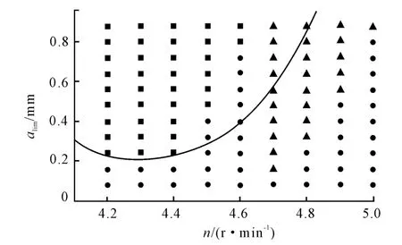
Figure 6.Time domain simulation result is compared to frequency domain solution stability
The stability limit obtained using the frequency domain solution is shown in Figure 6 as a solid line.The results of time domain simulations are identified by dot(stable),box(Hopf bifurcation),and triangle(flip bifurcation).It can be seen from Figure 6 that a narrow band of increased stability is between 45 000 r/min and 46 000 r/min.This is accompanied by the spindle speed range from 47 000 r/min to 50 000 r/min which exhibits flip bifurcation behavior.
4.2.Time-domain stability analysis at low radial immersion
Three case points are selected for further study of stability behavior.The once-per-revolution sampled data is expressed as“+”symbol in all three simulations.
The simulation results of case point(n=46000 rpm and alim=0.8 mm)from Figure 6 are shown in Figure 7 and Figure 8,which demonstrates the time displacements and the x versus y plot respectively.

Figure 7.Simulation results for x and y direction displacements(n=46 000 r/min and alim=0.8 mm)

Figure 8.Plot of x versus y direction displacements(n=46 000 r/min and alim=0.8 mm)
The traditional Hopf instability can be seen in this simulation because the once-per-revolution sampled data appears as an elliptical distribution for Hopf instability.
Accordingly,the simulation results of case point(n=49 000 r/min and alim=0.6 mm)are shown in Figure 9 and Figure 10.
Obviously,Figure 9 and Figure 10 show the flip bifurcation.The synchronously sampled data now occur in two clusters after the initial transients attenuate in Figure 10.
Finally,the simulation results of case point(n=50 000 r/min and alim=0.7 mm)are shown in Figure 11 and Figure 12.

Figure 9.Simulation results for x and y direction displacements(n=49 000 r/min and alim=0.6 mm)
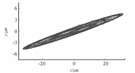
Figure 10.Plot of x versus y direction displacements(n=49 000 r/min and alim=0.6 mm)
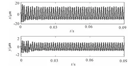
Figure 11.Simulation results for x and y direction displacements(n=50 000 r/min and alim=0.7 mm)
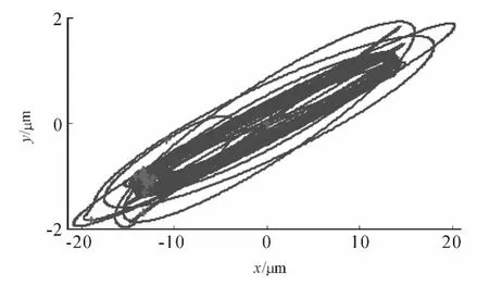
Figure 12.Plot of x versus y direction displacements(n=50 000 r/min and alim=0.7 mm)
As expected,Figure 11 and Figure 12 display repetitive behavior from one revolution to the next.A stable cut is observed in this simulation.
For those concerned with detailed process mod-eling,the exact nature of the milling instability(Hopf or flip bifurcation)is extremely clear.For practical machining applications,the radial depth of cut is needed to consider.When the radial depth of cut is low,additional stable zones appear that“split”the higher radial depth stability lobes.
5.Conclusion
This study presented a numerical analysis method to investigate the helical ball micro end milling process with variable radial immersion.The schematic diagram of ball micro milling is constructed and the cutting force calculation formula is derived taking account the dynamic cutting thickness based on helical square milling;then the cutting forces between the ball and square end mills are compared by time-domain simulation.In addition,the stability lobe of ball micro milling at low radial immersion is researched in detail through time domain and frequency domain methods.Finally,the time displacements and the x versus y plots are obtained,the Hopf and flip bifurcations are explored,and the simulation result between variable stability cases is deeply compared.
[1] Huang C Y.Mechanistic modeling of process damping in peripheral milling[J].Journal of Manufacturing Science and Engineering,2007,129:12-20.
[2] Quintana G,Ciurana J.Chatter in machining processes:A review[J].International Journal of Machine Tools and Manufacture,2011,51:363-376.
[3] Altintas Y,Eynian M,Onozuka H.Identification of dynamic cutting force coefficients and chatter stability with process damping[J].Annals of the CIRP,2008,57:371-374.
[4] Dornfeld D,Min S,Takeuchi Y.Recent advances in mechanical micromachining[J].Annals of the CIRP,2006,55:745-768.
[5] Cao Ziyang,Li H.Research on regenerative chatter in micro milling Process[J].Hydromechatronics Engineering,2012,40:17-20.
[6] Park S S,Malekian M.Mechanistic modeling and accurate measurement of micro end milling forces[J].Annals of the CIRP,2009,58:49-52.
[7] Campomanes M,Altintas Y.An Improved Time Domain Simulation for Dynamic Milling at Small Radial Immersions[J].Journal of Manufacturing Science and Engineering,2003,125/3:416-422.
[8] Merdol S,Altintas Y.Multi Frequency Solution of Chatter Stability for Low Immersion Milling[J].Journal of Manufacturing Science and Engineering,2004,126/3:459-466.
[9] Davies M,Pratt J.Stability Prediction for Low Radial Immersion Milling[J].Journal of Manufacturing Science and Engineering,2002,124/2:217-225.
[10] Davies M,Pratt J.The Stability of Low Radial Immersion Milling[J].Annals of the CIRP,2000,49(1):37-40.

- 機床與液壓的其它文章
- Numerical simulation of the double suction balance type screw compressor working process*
- Parameter optimization of electro-hydraulic proportionalsystem of PID based on the improved ant colony algorithm
- Flying cutter machining and cutter design based on the machining principle of cycloid rotational indexing
- Simulation of multi-modal control in electro-hydraulicposition servo-system*
- Optimal design and security verification of flying cutterbased on finite element analysis
- Robustness simulation of control algorithm for human-simulated intelligence based fusion*