基于有限元的22T液壓挖掘機主泵控制閥和泵殼體間隙分析*
2014-08-22 11:23:06趙永強周玉祥哈爾濱工業大學機電工程學院哈爾濱5000山東常林集團高端裝備研究院北京研發中心北京0008
機床與液壓 2014年24期
關鍵詞:有限元
怯 軍,劉 明,趙永強,周玉祥.哈爾濱工業大學機電工程學院,哈爾濱 5000.山東常林集團高端裝備研究院北京研發中心,北京 0008
1.Introduction
The 22-ton classic hydraulic excavator in China market is usually equipped with a drive through piston pump with a displacement of 112 mL/r,which provides the main power for the traveling and working systems.Based on the survey results of performance for hydraulic system,it was found that there existed a clearance at the interface between servo control valve and pump housing body if the discharge pressure,which is also the system pressure,reached to some degree high.
When the same experiment was conducted in a test lab,this phenomenon was repeated and the oil leakage was observed.As shown in Figure 1,the clearance was observed at a pressure shock test.The clearance space could be measured by a feeler gauge,the size of that is about 0.02 mm high.
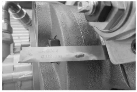
Figure 1.The clearance between the servo valve and pump housing body
Generally speaking,the presence of clearance might be related to the following factors:①sealing conditions between servo control valve and pump housing body;②physical properties of pump housing materials and valve body materials;③discharge pressure;④structure of the servo control valve;⑤physical properties of joint bolts;⑥fasten torque on joint bolts.The impacts of factor③,⑤,and⑥ on the clearance size were investigated in this paper to understand how the clearance was formed as well as how to optimize pump design to eliminate the clearance in the following sections.
2.Mechanical and FEM analysis
2.1.Pump working principle and mechanical analysis
The hydraulic diagram of the pump is shown in Figure 2.The front pump is taken to briefly explain the pump working principle since it is well-known to most hydraulic system engineers.

Figure 2.Hydraulic diagram of the main pump being used in 22-ton excavators
During working cycles,the discharge pressure is feed back into the displacement control cylinder and the servo control valve by internal channels from point 1 to point 2,and from point 1 to point 3.Meanwhile,other pressure signals coming from the front pump,the rear pump,and the pilot pump as well as system load will act together through the servo control valve to regulate pump displacement to provide required power and meet the demands of system.
The interface mentioned-above between the servo valve and housing body is shown in Figure 3,from which it could be seen that there is a control spool in the displacement servo control valve.
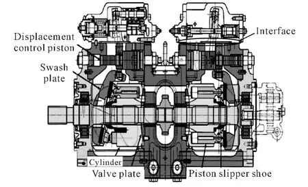
Figure 3.The interface between the control valve and pump housing body
Figure 4 shows the top and bottom view of the displacement servo control valve.The high pressure channel is marked in red color and the drain pressure channel is in green.From Figure 4,one could understand that all forces acting on the valve body are①the bolt preload F1;②the tensile force caused by discharge pressure(in red color)F2 and housing drain pressure(in blue color)F3.F2 and F3 could be the load of F1.As compared to F2,F3 is much smaller and such force could be ignored in the following analysis.
According to the traditional joint bolt connection theory[1],the strength of joint bolts should be verified to make sure if it is well designed.The related design data are listed as follows:the effective area of each single discharge channel(in red color)is 95 mm2,the size of the joint blot is M8 ×1.0,the fasten torque on each bolt is29 N·m,the coefficient of friction between the servo valve and the housing body is 0.15[1].Through the relationship between bolt fasten torque and preload[2],one could obtain:

Where,T is the bolt fasten torque,N·m;Ktis the torque coefficient,average value is 0.2[2];F'is the preload on the joint bolt,N;d is the main diameter of the joint bolt,m.
Then,the bolt preload F',transferred from bolt fasten torque is 18 125.00 N by using of Eq.(1).
The total preload F1 of four bolts is

Since the rated pressure of the pump is 35 MPa[3],the discharge pressure is set to 35 MPa to theoretically calculate the force F2scaused by each individual high pressure channel.Then:

The total force is:

According to the joint bolt connection theory[1],the resultant load on bolt is much greater than zero,i.e.,there is no clearance space occurring at the interface theoretically.However,because of the irregular distribution of these high pressure channels and elasticity of the servo valve body,it is possible to observe the clearance occurring at a local area where the effect of preload is weak.To find the location and the clearance size,a FEM method will be used.Each force inputted into the FEM model will be the same as above-mentioned values when the FEM calculation was carried out.
2.2.FEM analysis
2.2.1.FEM model and its simplification
The focus of the FEM analysis is the interface between the servo control valve and the housing body.In order to decrease the computational costs,the FEM model will be simplified by just applying a part of housing body for the FEM calculation,as shown in Figure 5.The housing body is treated as a base and fixed as a constraint to the servo valve.
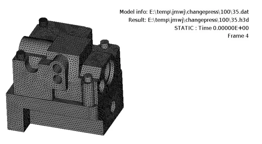
Figure 5.Simplified FEM model
To achieve a given degree of accuracy ,a linear tetrahedral element is picked up to build FEM mesh and it is assumed that each element has the same size.All joint bolts,servo control valve body,and the pump housing body are treated as an ideal linearelastic material and only Poisson’s ratio and elasticity modulus will be taken into account for the calculation。The properties of each part are listed in Table 1.
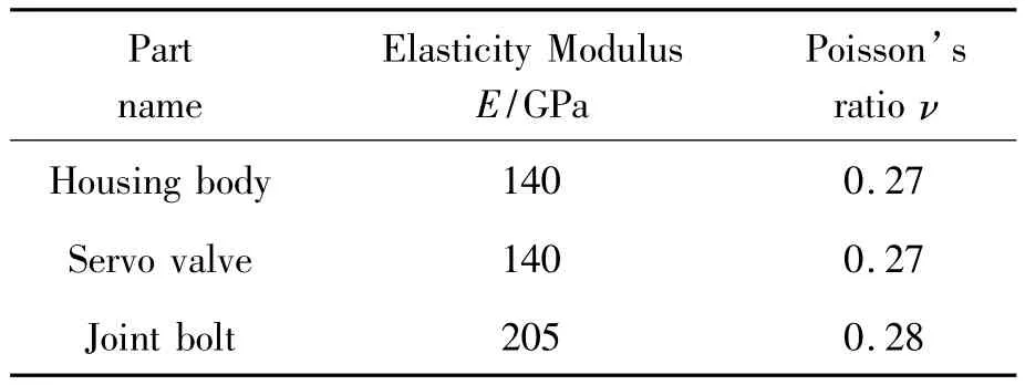
Table 1.Mechanical data of each material[4-5]
2.2.2.Contact boundary conditions
The contact problem is a type of non-linear issue.When the contact analysis is conducted and simulated,contact parameters such as the size of contact area and distribution of contact stress are changeable,which are obviously affected by material stiffness.Iterative method is a general technique to solve nonlinear problems.Due to the non-linear characteristics of this model,the full Newton-Raphson with adaptive descent method is adopted to execute the equilibrium iteration.The variable contact area could be defined as the actual touched area caused by F2sbetween the servo valve and the housing body.The area is,of course,changeable with time.
2.2.3.Load boundary conditions
The thread of each joint bolt is defined as a contact.Preload F',and extensile force F1 are the loads exerted on the thread.The contact area caused by bolt head and the servo control valve is supposed to be a rigid connection.A normal force is exerted on the interface owing to the high pressure,the value of the force is F2sand total force is F2.
2.2.4.FEM calculation and verification
The system pressure is set to the rated pressure 35 MPa and the fasten torque on each blot is rated as bolt torque 29 N·m.The distribution and the clearance size are then calculated based on the above FEM model.The numerical results are shown in Figure 6.
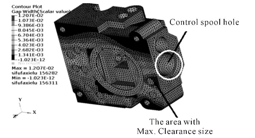
Figure 6.FEM results of the clearance size
In Figure 6,the maximum size of the clearance space is 0.012 mm featured by the red area.The location of the space is between two joint bolts and is close to the servo control spool hole.As compared to Figure 1,it could be seen that the location is the same as that identified by the lab test.The reason why it is the area that has the maximum clearance size is that the servo control spool hole makes structure strength of the servo control valve at the location becoming weak as compared to the other locations.The value 0.012 mm is smaller than 0.02 mm which is measured from the pressure shock test as mentioned above.In the light of test code[6],the peak pressure is greater than 35 MPa.Therefore,the FEM result of 0.012 mm is reasonable and acceptable as the pressure inputted into the FEM model is only 35 MPa.It is also noting that there is no clearance occurring at the locations around joint blots.This could be explained as the same as the conclusion from the above mechanical analysis.
From the application point of view,it is very important to know the relationship between the clearance size and the discharge pressure as well as the fasten torque on joint bolts.To do the investigation,the fasten torque and high pressure are changed simultaneously to simulate most possibilities happened in actual applications.All clearance size data responding to combinations of different fasten torque and discharge pressure is listed in Table 2.
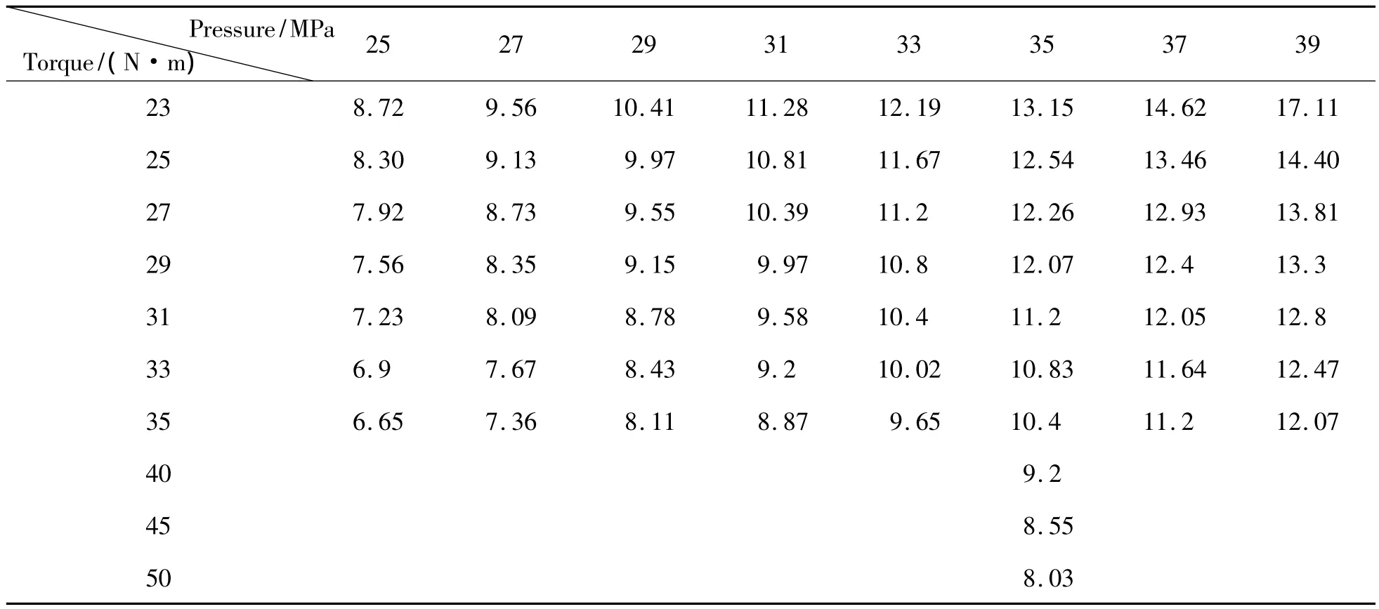
Table 2.Clearance size responding to the different preload and pressure combinations(Unit:mm)
Transform the data into a diagram with the fasten torque and system pressure as abscissa,respectively,the relationships will be shown in Figure 7 and Figure 8.
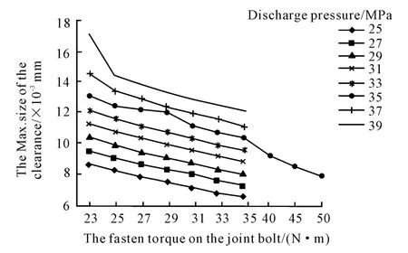
Figure 7.The max.size of the clearance V.S.fasten torque
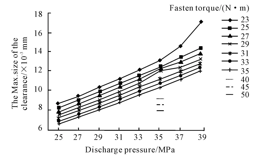
Figure 8.The max.size of the clearance V.S.system pressure
From Figure 8,it is clear that the maximum size of the clearance is approximately proportional to the system pressure if the fasten torque is fixed.From Figure 7,the relationship is approximately inverse-proportional to the fasten torque if the system pressure is fixed.No matter what combinations are,the location of the maximum clearance size will be unchangeable,and it is located between the two joint blots and close to the control spool hole.
Based on the approximately linear relationship between the clearance size and discharge pressure,one could extract the clearance size under the pressure shock situation:the system pressure is 43.75 MPa[6]as well as the fasten torque is 29 N·m.The maximum clearance size under the situation is 0.015 mm.As compared to the size of 0.02 mm measured in Figure 1,0.015 mm is an acceptable result if the measurement errors and FEM model simplification are taken into account.
It is obvious the clearance,on the one side,will lead to oil leakage if the size is greater than the size of elastic deformation of the o-rings;on the other side,it will cause early fatigue failures of o-rings sealing nearby the location if the system pressure is changed very often from high value to low value or vice versa.More seriously,a mass oil leakage will default the displacement control function.All defects are not expected during the working process of pump and they should be eliminated from design point of view.Since the clearance is associated with valve structure and material properties,some optimized designs will be discussed as follows to inspire how to reduce and/or avoid these above-mentioned defects.
3.Design optimization and improvement of the servo valve structure
The optimization work focuses on re-designing of valve structure.For the comparison reason,a socalled“standard”situation is defined as the discharge pressure is 35 MPa and the bolt fasten torque is 29 N·m.The following 4 design options are discussed with pros and cons.
3.1.Increasing the height of the servo valve body
The first solution of servo valve optimization is to increase the height of the body.
Under the standard situation,the increase of valve body height will reinforce the stiffness of the valve and reduce the clearance size accordingly.In the present paper,the valve height,which is defined from the valve top face to the interface,is increased by 50 mm which is higher than the original height at the FEM model.The clearance size will then be reduced from 0.012 mm to 0.004 mm which is getting pretty much smaller as shown in Figure 9.However,one of the cons of the option is that the cost and weight of the valve body will be increased thereby.
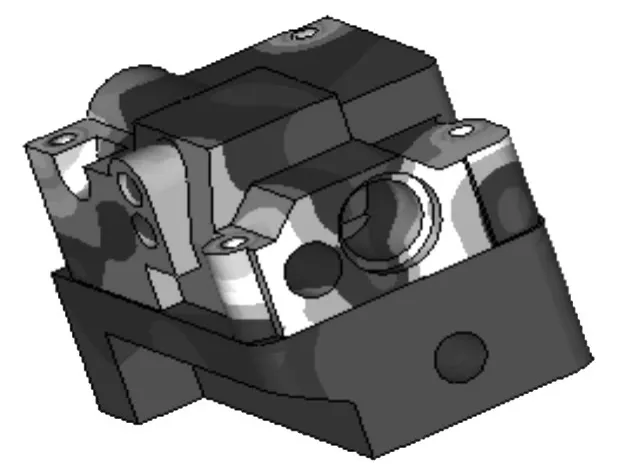
Figure 9.Servo valve optimization:increase the height of the body
3.2.Increasing the number of joint bolts
Keep the valve height and other structure features unchangeable,another optimization solution is to place an extra joint blot close to the clearance location as shown in Figure 10.
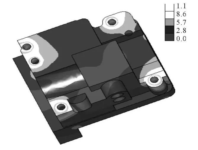
Figure 10.Servo valve optimization:increase joint bolts
The bolt number is then changed from four to five.Under the standard situation,the maximum clearance size will be reduced to 0.002 mm by the FEM calculation.The defect of this solution is that the interference might be caused between the location of the increased bolt and already existing internal channels if the location of the extra joint bolt is not well designed.
3.3.Change the distribution of discharge pressure channels
Since the above two solutions will cause extra costs,the third solution is provided to relocate high pressure channels as shown in Figure 11.
The design aims to make high pressure channels approach joint bolts much closer to reduce the clearance size since the resultant preload on each bolt is much greater than zero.As shown in Figure 11,the location of one high pressure channel is moved close to a joint bolt.Under the standard situation,the maximum clearance size will be changed to 0.005 mm.The potential issue of the solution is also the interference problem when the channel distribution is changed.
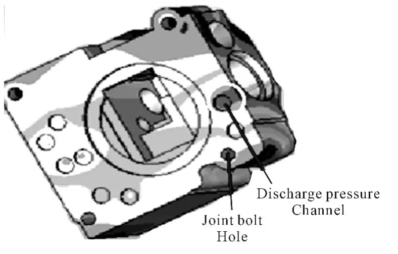
Figure 11.Servo valve optimization:change the location of high pressure channels
3.4.Increase the fasten torque on each joint bolt
A nature thinking of how to eliminate the clearance is to increase the fasten torque on each blot.From Table 2,it is shown that if the fasten torque is changed from 29 N·m to 50 N·m,the maximum clearance size is therefore changed from 0.012 mm to 0.008 mm.
All solutions discussed above can achieve the goal and the clearance size will be decreased.For any specific design,the designer is suggested to consider the total costs,manufacture process,structure interference and other factors to make the final optimization solution.
4.Conclusion
Based on what have done in this paper,some conclusions could be drawn as follows:
1)According to the joint bolt connection theory,there is no clearance occurring at the interface.
2)By using the FEM model,the maximum clearance size is approximately proportional to the discharge pressure and approximately inverse-proportional to the fasten torque on each bolt.
3)Under the pressure shock situation with high pressure at 43.75 MPa,the maximum clearance size is around 0.015 mm which is close to the lab test result.
4)All three optimization designs have obvious effects on reducing the clearance size.
5)The design of the final optimization solution should consider the original structure,costs,and manufacture ability comprehensively.
[1] XuanhuaiQiu,Mechnical Design[M].3rd edition,Beijing:High Education Press,1989.
[2] Joseph E S,Charles R M,Mechnical Engineering Design[M].6th Edition,New York:McGraw Hill Education.
[3] Data sheet of K3V pump from KPM[M].
[4] Grey iron castings,Standardization and Administration of The People’s Republic of China[M].Beijing:China Machine Press,2010:13.
[5] The data book of Mechanical Engineering materials,Editorial Committee of the data book[Z].1994.12:264,752.
[6] Hydraulic Axial Piston Pumps[M].Beijing:China Machine Press,2006.
猜你喜歡
艦船科學技術(2022年20期)2022-11-28 08:19:18
數學物理學報(2022年4期)2022-08-22 04:09:28
減速頂與調速技術(2020年4期)2020-11-22 07:20:26
上海節能(2020年3期)2020-04-13 13:16:16
石油化工建設(2019年6期)2020-01-16 08:03:42
天津醫科大學學報(2019年6期)2019-08-13 07:04:32
鍛壓裝備與制造技術(2016年3期)2016-06-05 09:36:08
機械工程師(2015年10期)2015-02-02 01:14:03
機電產品開發與創新(2014年4期)2014-03-11 16:42:24
上海金屬(2013年4期)2013-12-20 07:57:18
