Exploration of Advanced Bistatic SAR Experiments
2014-08-05 03:35:02DengYunkaiRobertWang
雷達學報 2014年1期
關鍵詞:實驗
Deng Yun-kai Robert Wang
(Space Microwave Remote Sensing System Department, Institute of Electronics, Chinese Academy of Sciences, Beijing 100190, China)
Exploration of Advanced Bistatic SAR Experiments
Deng Yun-kai Robert Wang*
(Space Microwave Remote Sensing System Department, Institute of Electronics, Chinese Academy of Sciences, Beijing 100190, China)
This study concentrates on the results of several advanced hybrid bistatic SAR experiments. The hybrid bistatic configuration applies to the case in which the transmitter and receiver are mounted on different types of platforms,e.g., spaceborne/airborne, airborne/stationary, spaceborne/stationary, and so on. Several hybrid bistatic SAR experiments have been performed successfully,i.e., TerraSAR-X/PAMIR, PAMIR/stationary, and TerraSAR-X/stationary. Furthermore, Multiple Baseline Interferometry SAR (MB-InSAR) and Digital Beam-Forming (DBF) technologies are validated in the TerraSAR-X/stationary configuration. Note that the DBF experiment results based on the spaceborne illuminator are discussed for the first time in SAR community. In addition, this paper emphasizes imaging geometry, image analysis, and focusing results.
Bistatic Synthetic Aperture Radar (BiSAR); Multiple Baseline Interferometry SAR (MB-InSAR); Digital BeamForming (DBF); TerraSAR; PAMIR
CLC index: TN958
1 Introduction
Bistatic Synthetic Aperture Radar (BiSAR) is characterized by spatially separated transmitter and receiver, and hence offers considerable capability, reliability and flexibility in designing SAR missions[1,2]. Such a spatial separation brings additional benefits in comparison with its monostatic counterpart: illuminators of opportunity with several receive-only systems and also the possibility of forward- or backward-looking SAR imaging[1-6]. Hybrid bistatic systems appear to be interesting in this context, as they allow lightweight receive-only UAVs (Unmanned Aerial Vehicles), or flexible stationary receivers with many potential spaceborne illuminators to produce bistatic SAR images[5,6].
The spaceborne/airborne bistatic SAR experiments have been successfully conducted in 2008 and 2009 by the Fraunhofer institute for High frequency physics and Radar (FHR) techniques, employing FHR’s airborne radar system PAMIR as the separate receiver. For FHR’s experiments, TerraSAR-X operated in the sliding spotlight mode,whereas PAMIR worked in two different modes: stripmap mode and inverse sliding spotlight mode. The airborne/stationary experiment has been successfully performed in 2007 by using PAMIR acting as a moving receiver and a stationary transmitting horn antenna. Several spaceborne/ stationary bistatic experiments have been successfully realized in 2009, where TerraSAR-X was used as the transmitter and two stationary receivers are equipped with two different horn antennas: one is to record the echo signal from the illuminated scene and the other is for the direct signal from TerraSAR-X, respectively.
These hybrid experiments not only demonstrated the feasibility of the azimuth-variant bistatic configuration, but will also offer an excellent opportunity to validate new bistatic SAR processing algorithms, bistatic synchronization and imaging techniques, especially for the azimuth- variant case.
To further explore the potential applications of Bistatic SAR, MB-InSAR and DBF technologies are validated in the spaceborne/stationary configuration experiments, showing great application potential of hybrid bistatic SAR operations.
This paper is organized as follows. In Section 2, we will show the focusing results of several hybrid bistatic SAR experiments and address the characteristics of the bistatic SAR image. In Section 3, some conclusions will be reported.
2 Focusing results
2.1 Spaceborne/airborne experiments
In the spaceborne/airborne configurations, TerraSAR-X was steered as the illuminator in the sliding spotlight mode, whereas PAMIR, mounted on a Transall C-160, operated in the stripmap mode or inverse sliding spotlight mode. The sliding spotlight mode is characterized by steering the beam around a virtual point, stead of the scene center, shown in Fig. 1 and Fig. 2. The virtual rotation point of the spaceborne platform (shown in Fig. 1 and Fig. 2) is beneath the earth’s surface and far away from the scene center. The inverse sliding spotlight mode is a special case of the sliding spotlight mode where the virtual rotation point (shown in Fig. 2) is located behind the platform in the sky.
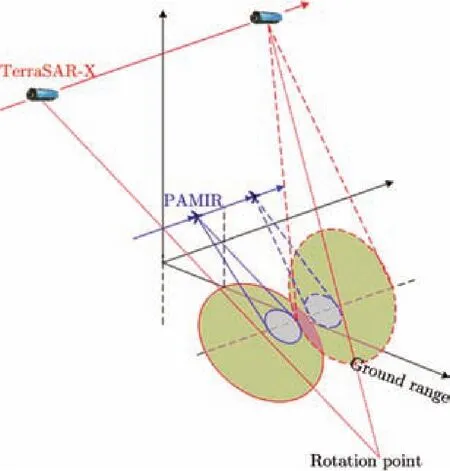
Fig. 1 Imaging geometry in spaceborne/airborne bistatic SAR configuration (sliding spotlight/ stripmap mode)
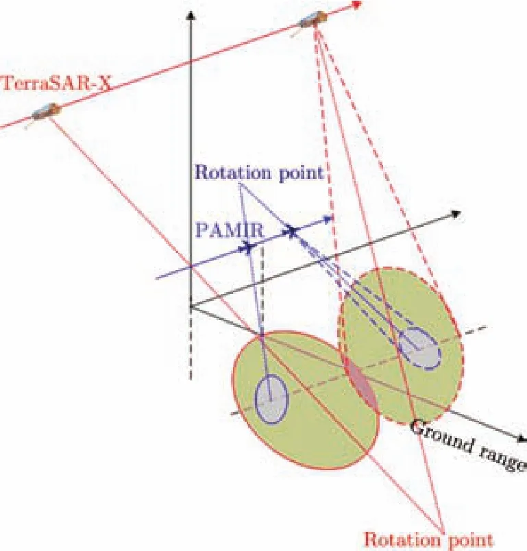
Fig. 2 Imaging geometry in spaceborne/airborne bistatic SAR configuration (sliding spotlight/ inverse sliding spotlight mode)
In these two experiments, the windowed data acquisition is synchronized with the directly received satellite pulses. After this synchronization signal, the PAMIR works according to its own clock. However, the resulting Pulse Repetition Interval (PRI) of the receiver was not accurate at integer times. Therefore, a fraction of the PRF mismatch remained[6]. It led to the drift of the sampling window with the increase of azimuth time. This drift must be compensated in the azimuth time domain. After compensating the time-variant drift, the acquired raw data can be focused in the frequency domain[4], and the final images are shown in Fig. 3 and Fig. 4.
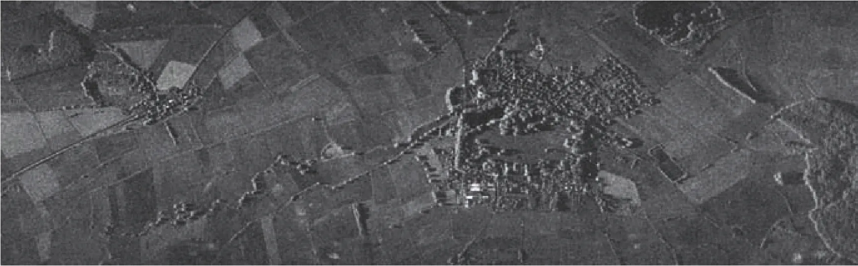
Fig. 3 BiSAR image (sliding spotlight/stripmap mode). (Raw data delivered by Fraunhofer FHR)
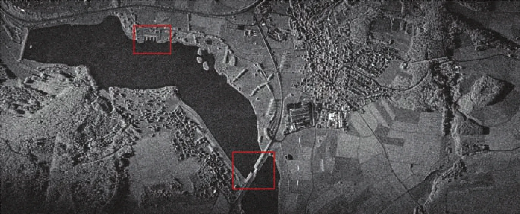
Fig. 4 BiSAR image (sliding spotlight/inverse sliding spotlight mode). (The horizontal and vertical directions denote the range and azimuth, respectively. Raw data delivered by Fraunhofer FHR)
For the first experiment (i.e., sliding spotlight/ stripmap mode), we have analyzed the differences between the monostatic SAR image and bistatic SAR image in Ref. [6]. In this paper, we further show the differences between the monostatic SAR image and bistatic SAR image acquired in the second spaceborne/airborne SAR experiment. For more details, the areas in the bistatic SAR image, marked by the solid line, are zoomed, and chosen for comparison with the corresponding PAMIR monostatic SAR image, shown in Fig. 5. In Figs. 5(a)~5(c), the corner reflectivity is very strong, and thus the target appears to be bright. However, the strong reflectivity in the bistatic SAR image is invisible due to its different illumination geometry and scattering mechanisms.
2.2 Airborne/stationary experiment
This airborne/stationary bistatic experiment was successfully performed in 2007. The imaging geometry is shown in Fig. 6. In this experiment, PAMIR worked in the spotlight mode, acting as a moving receiver. The transmitter was located above the Rhine valley near the city of Bonn. Transmitter and receiver had an azimuth beam width of 27° and 6°, respectively. Both transmitter and receiver worked at X-band and shared a common bandwidth of 380 MHz with a center frequency of 9.65 GHz. Because of complex flight condition, the airplane has a nominal flight direction of 282.034° with a yaw angle of 286.24° in the North-East-Up coordinate system. It means that the experiment is performed in low squint mode.
For the moving/stationary configuration, only the moving platform contributes to the azimuth modulation, whereas the stationary platform introduces a range offset to the range migration trajectories of targets at the same range. The offset is determined by the azimuth position of different targets with respect to the stationary platform[6]. It is the space-variant offset that makes it difficult processing in the frequency-domain. By using the imaging algorithm presented in Ref. [6], the focused bistatic SAR image is shown in Fig. 7.
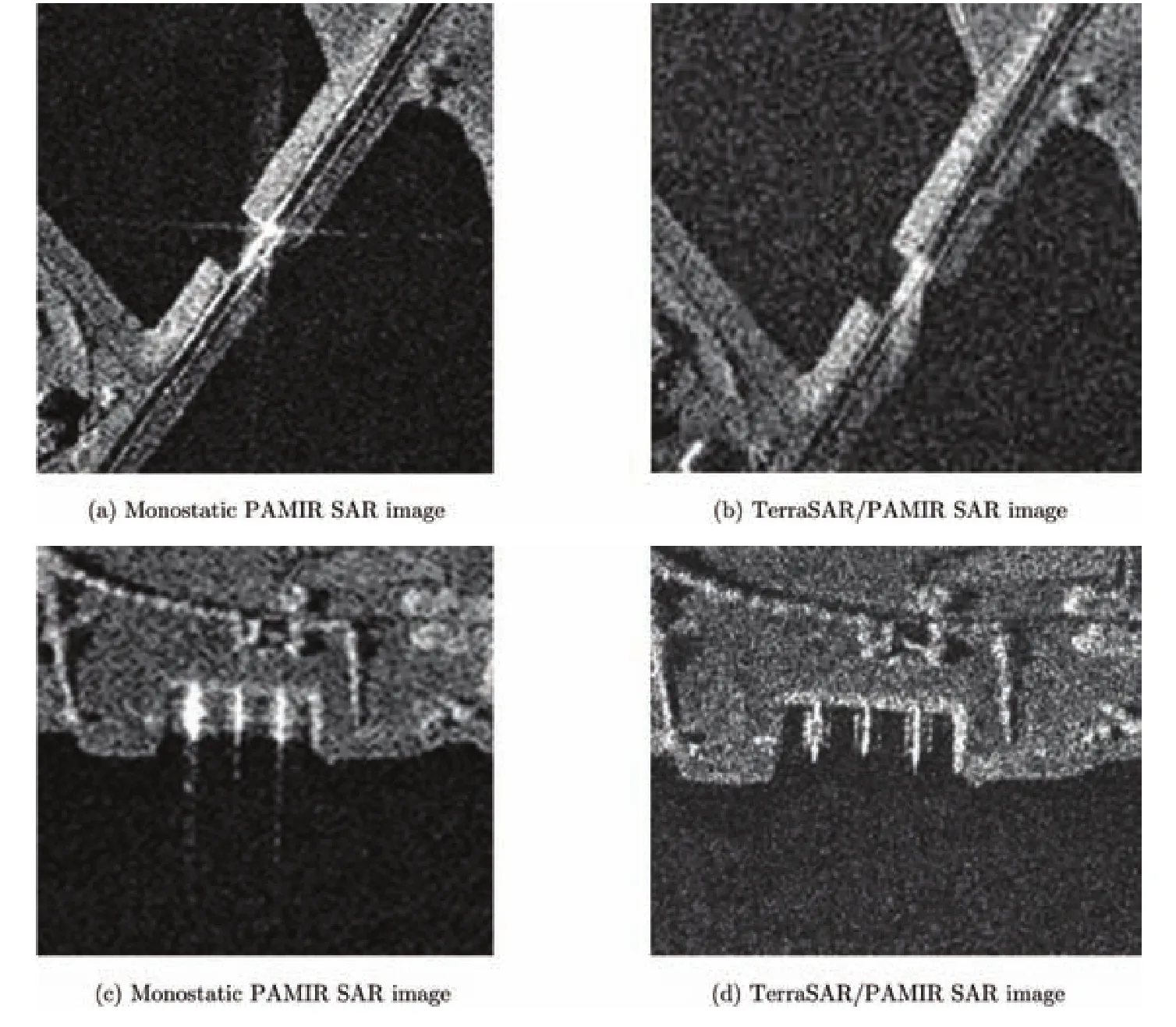
Fig. 5 Comparison of monostatic SAR and bistatic SAR images
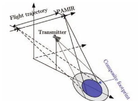
Fig. 6 Imaging geometry in the airborne/ stationary configuration

Fig. 7 Airborne/stationary bistatic SAR image. (The horizontal and vertical directions denote the range and azimuth, respectively. Raw data delivered by Fraunhofer FHR)
Because a stationary transmitter was used, the illumination pattern of the horn antenna becomes clearly visible. From the composite illumination pattern unsymmetrical in the vertical direction, it can also be seen that the receiver worked in the low squint mode. In addition, large shadows are present due to the small depression angle of the horn antenna (5°).
2.3 Spaceborne/stationary experiments
This spaceborne/stationary bistatic experiment was successfully performed in 2013 in China. The imaging geometry is shown in Fig. 8.
In this experiment, TerraSAR-X works as the transmitter in sliding spotlight mode, the receiver, who has three echo channels, is located on the ground in the mountain area of Beijing, and provides three SAR images simultaneously. The transmitter and receivers work at 300 MHz bandwidth. The size of the scene is 5 km in range direction and 5 km in azimuth direction, covering both mountain areas urban areas as shown in Fig. 9(b). The focused image is shown in Fig. 9(a)[7,8]. As one can see, the focusing result shows good performance, which proves the success of spaceborne/stationary bistatic experiment.
2.3.1 MB-InSAR experiment In order to explore the potential of the hybrid bistatic SAR, MBInSAR experimentin the spaceborne/stationary hybrid bistatic SAR configuration has been carried out, who shows advantages in reducing the temporal decorrelation and atmospheric effects, avoiding the additional process for Doppler frequency spectra layover, providing more flexible designing and higher precision, solving the unwrapping problem easily and obtaining more accurate results in the building areas.
The data of urban area is used to validate the performance of the spaceborne /stationary bistatic SAR interferometry experiment. Fig. 10 shows the unwrapped phase using iteration multi-baseline unwrapping method with traditional unwrap process (reducing the low interferometric correlation points). Fig. 10(a) shows the unwrapped result with 0.8 m baseline. The building area is shown in red rectangular and tree area is shown in green rectangular. Fig. 10(b) shows the unwrapped result using single 3.2 m baseline, which is uncorrected unwrapped. Fig. 10(c) shows the unwrapped result using iteration multi-baseline unwrapping method with traditional unwrapping process. The comparison of those results shows that the iteration multi-baseline unwrapping method with traditional unwrapping method combine the advantage of the short baseline that the unwrapping process is easy and the advantage of the large baseline that the relative precision is high.
Fig. 11(a) shows the result of the multibaseline approach and Fig. 11(b) shows the result of the 0.8 m single-baseline. The comparison shows that the Signal to Noise Ratio (SNR) of the singlebaseline is lower than that of multi-baseline approach.
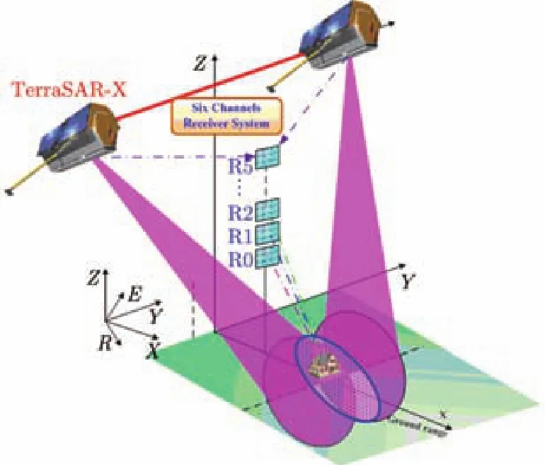
Fig. 8 Imaging geometry in the spaceborne/ stationary configuration
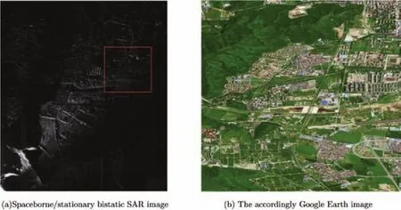
Fig. 9 The spaceborne/stationary bistatic SAR image and the accordingly Google Earth image (The horizontal and vertical directions denote the range and azimuth, respectively. Raw data delivered by IECAS)
2.3.2 DBF experimentFor future spaceborne SAR remote sensing applications, the capacity of high resolution and wide coverage imaging is especially emphasized. However, conventional SAR system can not meet this requirement due to the fact that the unambiguous swath width and achievable azimuth resolution pose contradicting requirements on system design. The main innovative characteristic of this promising concept is the use of multichannel in elevation and/or azimuth where the receiving antenna is either split into multiple subapertures with independent receiver channels or the receiver apertures are distributed on multiple platforms leading to a multistatic SAR[1,7,9]. Furthermore, with the recorded digital signal, DBF technology can be employed to jointly spatiotemporal-frequency synthesize multiple dynamic digital receiver beams to produce one or more digital receiver beams, each covering an unambiguous range segment with high resolution in azimuth[9].
In our experiment, BiSAR using TerraSAR-X as the illuminator combined with multi-channel receiver in elevation is implemented to validate DBF technology. In this experiment, TerraSAR-X works as transmitter in spotlight mode at 150 MHz bandwidth.
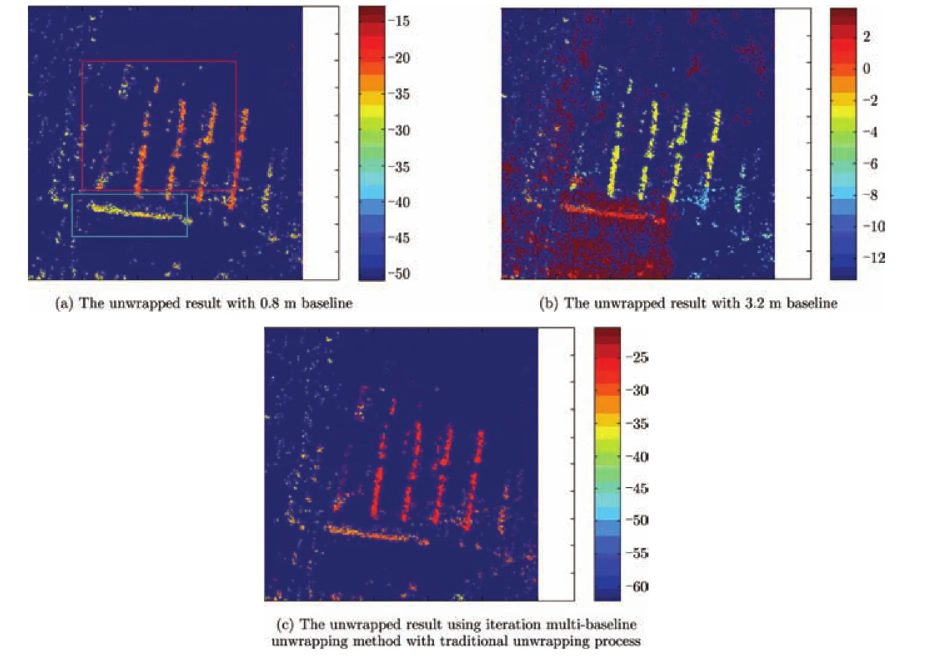
Fig. 10 Unwrap phase using iteration multi-baseline unwrapping method with traditional unwrapping process
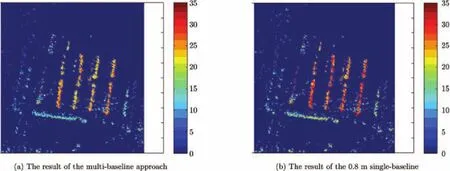
Fig. 11 Height estimation result
In this experiment, the TerraSAR-X works as the transmitter in the sliding spotlight mode, while the multi-channel receiving antenna in elevation on the ground is used to form the narrow and high gain beam scanning. The beam follows the pulse echo reflected from different directions. Fig. 12 shows the photo of the waveguide radiator used in this paper. The simulated pattern results at 9.6 GHz of subarray and full array are shown in Fig. 13. The detailed parameters are summarized in Tab. 1.
In our experiment, the ground receiver has five echo channels. The corresponding image is shown in Fig.14. Fig. 14(a) is the imaging result with one channel and Fig. 14(b) is the BiSAR-DBF result using five channels. The zoom-up images of block areas are shown in Fig. 14(c) and Fig. 14(d).
From the Tab. 2, it can be seen that the average SNR of all five echo channels is 17.098 dB. It means that the SNR of SAR image with DBF processing can be improved about 6.527 dB compared with the average SNR of all five receiving channels. The improvement of the above-mentioned SNR agrees with the theoretical value of 6.9 dB.
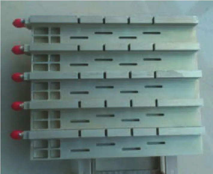
Fig. 12 Photo of the waveguide antenna
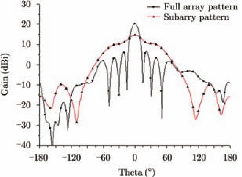
Fig. 13 Simulated patterns of full array and subarray at 9.6 GHz
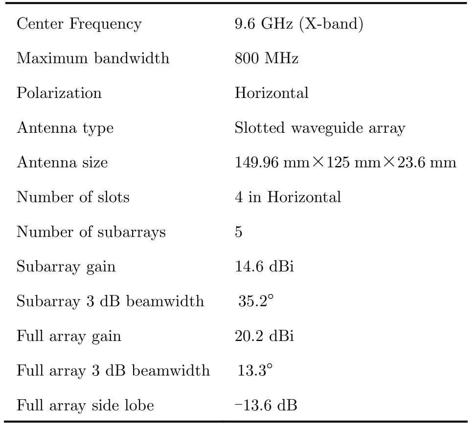
Tab. 1 Waveguide antenna’s electrical patameters
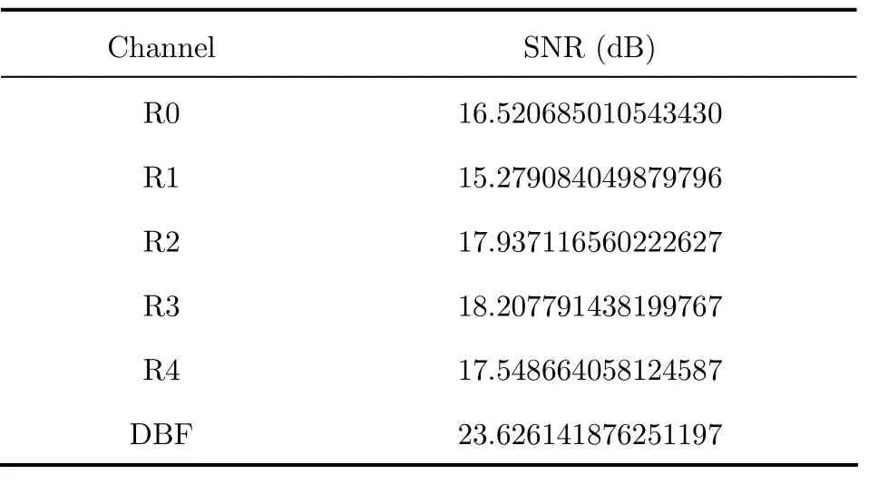
Tab. 2 The SNR of the images
3 Conclusion
These successfully performed bistatic SAR experiments have validated our frequency-domain focusing algorithms, especially azimuth-variant focusing features. In addition, they are helpful to analyze characteristics of bistatic SAR images, and to exploit the potential of bistatic SAR. Moreover, the successful experiment also validated our synchronization strategies.
AcknowledgementThis work reported herein is funded jointly by DFG (German Science Foundation), the DLR Project and Hundred Talents Program of Chinese Academy of Sciences, which is seen as a key item of their work. Finally the authors must thank our colleagues, Prof. Dr. Loffeld, Prof. Dr. Ender, Dr. Nies, Dr. Walterscheid, Mr. Espeter, Dr.Klare, Mr. Shao Y F, Mr. Tang J W, Mr. Wang W, Mr. Liu G, Dr. Wang N, Mr. Wu X Y, and Dr. Shun H F for their important contributions to this work.

Fig. 14 Spaceborne/stationary bistatic SAR image with one channel and DBF technology. (Raw data delivered by IECAS)
[1] Krieger G and Moreira A. Spaceborne bi- and multistatic SAR: potential and challenges[J].IEE Proceedings-Radar,Sonar and Navigation, 2006, 153(3): 184-198.
[2] Massonet D. Capabilities and limitations of the interferometric cartwheel[J].IEEE Transactions on Geoscience and Remote Sensing, 2002, 39(3): 506-520.
[3] Wang R, Loffeld O, Nies H,et al.. Chirp scaling algorithm for the bistatic SAR data in the constant-offset configuration[J].IEEE Transactions on Geoscience and Remote Sensing, 2009, 47(3): 952-964.
[4] Wang R, Loffeld O, Nies H,et al.. Focusing hybrid spaceborne/airborne bistatic SAR data using wavenumber domain algorithm[J].IEEE Transactions on Geoscience and Remote Sensing, 2009, 47(7): 2275-2283.
[5] Wang R, Loffeld O, Neo Y L,et al.. Focusing Bistatic SAR Data in Airborne/Stationary Configuration[J].IEEE Transactions on Geoscience and Remote Sensing, 2010, 48(1): 452-465.
[6] Walterscheid I, Espeter T, Gierull C,et al.. Results and analysis of hybrid bistatic SAR experiments with spaceborne, airborne, and stationary sensors[C]. 2009 IEEE International Geoscience and Remote Sensing Symposium, Cape Town, South Africa, 2009: Ⅱ238-Ⅱ241.
[7] Wang R, Deng Y, Shao F,et al.. Double-channel bistatic SAR system with spaceborne illuminator[J].IEEE Transactions on Geoscience and Remote Sensing, 2013, 51(8): 4496-4507.
[8] Shao F, Wang R, Deng Y,et al.. The error analysis of bistatic SAR imaging and bistatic stereo-SAR[J].IEEETransactions on Geoscience and Remote Sensing, 2013, 151(8): 4518-4543.
[9] Krieger G, Gebert N, and Moreira A. Multidimensional waveform encoding: a new digital beamforming technique for synthetic aperture radar remote sensing[J].IEEE Transactions on Geoscience and Remote Sensing, 2008, 46(1): 31-46.

Deng Yun-kai was born in 1962. He is now a Research Fellow and Ph.D. supervisor of Institute of Electronics, Chinese Academy of Sciences. He has been the leader of several China spaceborne and airborne SAR programs and developed some key technologies of spaceborne and airborne SAR. Currently, he is the Deputy Director of IECAS. His current research interests include spaceborne/airborne SAR technology for advanced modes, multifunctional radar imaging, and microwave circuit design.
E-mail: ykdeng@mail.ie.ac.cn

Robert Wang was born in 1980. He is now a Research Fellow and Ph.D. supervisor of Institute of Electronics, Chinese Academy of Science, he is a Senior Member of IEEE. His main research interest is Bistotic SAR (BiSAR) and signal processing of FMCW SAR.
E-mail: yuwang@mail.ie.ac.cn
先進雙基SAR技術研究
鄧云凱 王 宇
(中國科學院電子學研究所航天微波遙感系統部 北京 100190)
該文展示了世界上幾個重要的先進混合雙基SAR實驗。混合雙基模式是指發射端和接收端分別裝載于不同類型的平臺,例如星載/機載,機載/靜止平臺,星載/靜止平臺等。近年來相繼有若干混合雙基 SAR實驗成功完成,主要包括TerraSAR-X/PAMIR,PAMIR/靜止平臺,以及TerraSAR-X/靜止平臺。此外,在TerraSAR-X/靜止平臺的雙基模式下還驗證了多基線干涉SAR (MB-InSAR)和數字波束形成(DBF)技術。值得強調的是,該文所展示的DBF實驗結果屬于世界上首次成功的基于在軌雷達衛星的DBF實驗。
雙基SAR (Bi-SAR);多基線干涉SAR (MB-InSAR);數字波束合成(DBF);TerraSAR;PAMIR
A
2095-283X(2014)01-0001-09
10.3724/SP.J.1300.2014.14026
Manuscript received February 10, 2014; revised February 10, 2014. Published online February 26, 2014.
Supported by Hundred Talents Program of Chinese Academy of Sciences.
*Corresponding author: Robert Wang.
E-mail: yuwang@mail.ie.ac.cn.
中國分類號:TN958
猜你喜歡
作文·小學低年級(2025年2期)2025-02-13 00:00:00
小雪花·小學生快樂作文(2024年11期)2024-12-31 00:00:00
作文·小學低年級(2024年2期)2024-04-29 00:00:00
作文·小學低年級(2023年3期)2023-04-29 00:00:00
小獼猴智力畫刊(2022年9期)2022-11-04 02:31:42
小主人報(2022年4期)2022-08-09 08:52:06
中學生數理化·中考版(2022年11期)2022-02-16 07:01:20
小哥白尼(趣味科學)(2019年6期)2019-10-10 01:01:50
發明與創新(2016年38期)2016-08-22 03:02:52
太空探索(2016年5期)2016-07-12 15:17:55
