粒子圖像測速技術在馬赫數4.0流場測試中的應用
2012-11-20 10:03:26榮臻,陳方,劉洪
實驗流體力學 2012年6期
榮 臻,陳 方,劉 洪
(1.上海交通大學航空航天學院,上海 200240;2.浙江大學航空航天學院,杭州 310027)
0 Introduction
To further promote the applications and developments of supersonic aerodynamics,more reliable and valid ground-based flow investigations need to be conducted,like in subsonic regimes.However,as traditional techniques for supersonic flow measurements,surface pressure sensors can only offer the surface flow properties and schlieren visualization is merely able to qualify the flow velocity flowfield with integration along the line of sight.Otherwise,hot wire anemometer and LDV can only give single-point measurement of velocity field.Therefore,aquantitative,large amount of data and planar even spatial diagnostic technique need to be developed to achieve the high-solution and high-precision evaluation of flow properties.
Particle Image Velocimetry(PIV)is a nonintrusive optical measurement technique and can allow the direct measurement of instantaneous,planar velocity vector field,so,this technique has been widely used in low-speed flow tests.During the last decades,PIV has been extended to measurements of high-speed flows characterized by shock waves and strong gradients due to lower inter-frame time CCD camera and larger energy double-cavity Nd:YAG lasers.The application of PIV in high-speed flows pioneered by Moraitis and Riethmuller[1]and Kompenhans and Hocker[2]allowed to identify some critical issues related to recording speed and seeding particle tracing accuracy.Recently,applications of PIV in supersonic flows were made lots of progress including base flow[3-4],jet impingement[5],supersonic mixing layers[6-7]and shock-wave/boundarylayer interaction[8-9].The key points of PIV applied to supersonic flows involved selection of appropriate seeding particles;their dispersion in the flows and the analysis of PIV recordings.
The aim of this paper is to applied PIV technique to measure the flowfield atMa=4.0in MMH wind tunnel.The free stream flow,an oblique shock wave over a ramp and flowfield over a corner were carefully tested in order to verify the reliability of PIV in supersonic flows.The seeding particle performance such as tracing ability was also carefully discussed.
1 Flow facility and models
1.1 Flow facility
The MMH(Multi-Mach number High-speed)wind tunnel is a blow-down intermittent facility designed forMa=2.5,3.0,4.0,5.0,6.0,7.0with a run time of more than ten seconds at Shanghai Jiaotong University.The nozzle isФ200mm in diameter and the flow inside the test chamber is optically accessible through three windows withФ250mm.A schematic of this wind tunnel along with its operating range is given in Fig.1.
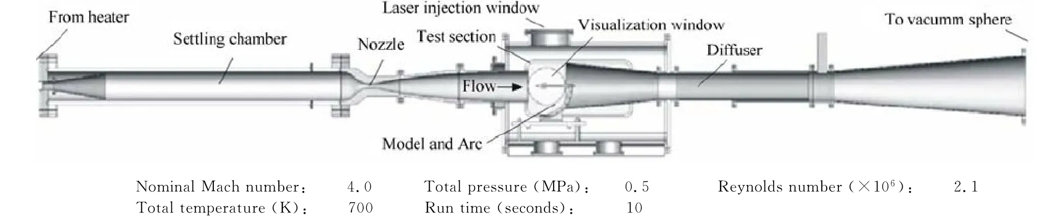
Fig.1 Sketch of wind tunnel and experimental operating parameters圖1 風洞示意圖及實驗運行參數
1.2 Wind tunnel models
There are two models used in the tests.A twodimensional ramp with a length of 28mm and a deflection angle is used to produce a two-dimensional oblique shock wave and measurement of seeding particle response across shock.Another model is a compression corner with 65mm in length,17.5mm in length and deflection angle used to produce a complex flowfield.The 3Dsketches of two models are shown in Fig.2.
2 Particle image velocimetry system
The two-components PIV system is composed of a double pulsed Nd:YAG laser at a wavelength of 532nm with a maximum energy of 500mJ and a du-ration of 6-8ns.A laser-light sheet(300mm wide,0.2mm thick)perpendicular to the nozzle axis is created by means of a optical arm and directed vertically into test chamber shown in Fig.3.An IPX-11Mcamera with 4000pix×2672pix(with a pixel size of 9μm×9μm)and a minimum pulse delay time of 0.4μs is mounted on the horizontal axis to view the illuminated flowfield beside test chamber,and it is equipped with 105mm SIGMA objective atf# =2.8. The cross-correlation of the PIV recording is performed with MicroVec 3.0.The interrogation windows of sizes 32pix×32pix is used with an overlap factor of 25%.The laser is operating atf=2Hz and almost 20pairs of PIV images are recorded during run time of 10seconds.TiO2particles are chosen for seeding.The nominal particle diameterdpgiven by the supplier is 30nm and a SEM (Scanning electron microscope)analysis yielded a dynamic diameter of about 250nm due to agglomeration effect.The particles are injected into the tunnel by the seeding system shown in Fig.4.The seeding concentration of TiO2was optimized by several preliminary experiments,and good results were obtained for a mass flow 0.02kg/s with the main flow 3kg/s,which corresponded to an estimated seeding density of almost 100,000particles/mm3in the test section at the time of capturing.More than 10particles per an interrogation window were meeting the requirement of cross-correlation operation.
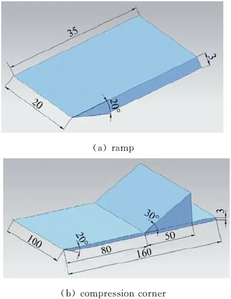
Fig.2 The 3Dsketches of test models圖2 實驗模型三維示意圖
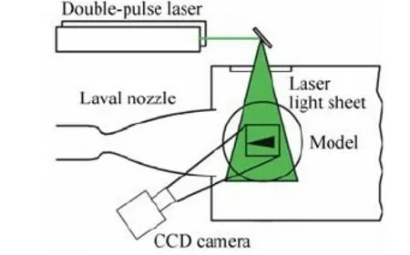
Fig.3 Sketch of PIV system installation圖3 PIV 系統布置示意圖
3 Experimental results
3.1 Free stream flow at Ma=4.0
As a basis of study,free stream flow assessment was presented firstly.The theoretical and PIV measured velocities were shown in Tab.1.The measured velocity results were found to be less than 1%in defect with respect to those calculated by adiabatic flow theory.
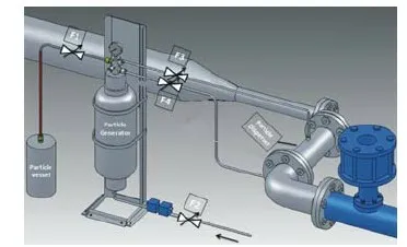
Fig.4 Schematic sketch of seeding system圖4 粒子布撒系統示意圖

Table 1 Comparison between the PIV measured velocity and theoretical velocity in free stream表1 自由來流PIV測量結果與理論值比較
The nozzle flow was measured by PIV atMa=4.0andT0=400K with a field of view of about 100×180mm2parallel to the axis of symmetry shown in Fig.5.The PIV picture(Fig.5(a))showed a rather homogenous TiO2particle seeding except for the upper and lower part of the nozzle where the interaction of the free stream boundary layer with expansion waves created a higher turbulence.The data analysis yielded a homogeneous flowfield(Fig.5(b))with a measured mean horizontal velocity of 793m/s that was very close to the calculated flow velocity of 787.5m/s.

Fig.5 Mach 4.0free stream flow圖5 馬赫數4.0自由來流結果
3.2 Flowfield over a ramp with 20°deflection angle
A ramp is a good test body in supersonic flows because a shock wave formed at the ramp tip causes a strong velocity gradient.For the present flow condition and ramp geometry,the shock wave is attached at the tip and the flow within the shock wave is uniform so that it can be calculated analytically usingthe gasdynamic shock relations.
For these reasons,a ramp with 20°deflection angle was mounted into the test chamber and measured for the Mach 4.0flow shown in Fig.6(a).To avoid laser light reflections,the ramp was painted black.The measured velocity distribution is shown in Fig.6(b)(Black area indicates the model).The averaged two-dimensional velocity distribution on the ramp corresponded very well to the calculated velocities shown in Tab.2.Additionally,the shock wave angles inferred from schlieren and PIV pictures were compared with the calculation by theory of perfect gas shown in Fig.6(c).and Tab.3,where a good agreement was similarly found.

Fig.6 尖劈流場測試結果圖6 Ramp flow

Table 2 Calculated and measured free stream velocity before the shock and horizontal(u)and vertical(v)velocities of the flow over a ramp after the shock表2 尖劈斜激波前后計算及實驗測試速度矢量分布
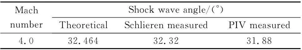
Table 3 Shock wave angle comparison表3 激波角比較
3.3 Flowfield over a compression corner
In order to validate the reliability of PIV applied to supersonic flows,a complex flowfield with flow separation and shock wave interference over a corner was tested shown in Fig.7(a).Compared to schiliren measurement results,the leading edge shock,separation shock,separation area and main shock were clearly visualized in PIV picture with similar locations.The measured velocity distribution was shown in Fig.7(b)(Black area indicates the model)and the results resolved by MicroVec 3.0were not so good as ramp,only the flowfield before main shock can be well calculated and the results after main shock seemed to be affected by speckle effect due to high concentration of seeding particles with low velocity.So the PIV algorithm need to be further improved to meet the requirements of complex flow tests.
4 Seeding particle performance
Supersonic flows exhibit strong velocity and density gradients due to shock waves so that seeding particle dynamic plays an important role for estimating the flow tracing capability.To predict particle dynamic behavior theoretically,a simplification of the equation of particle motion is used[10].The re-laxation time used by seeding particle across the shock wave is given by Eq.1:
The relaxation time of seeding particle can be estimated by measuring the particle response to an oblique shock wave generated by 20°deflection ramp.The measured horizontal and vertical velocity component along the shock wave vertical direction are plotted in Fig.8.They show that the tangential velocity component remains unchanged across the shock wave as expected by theory and the normal velocity component is decelerated within a distance as the relaxation lengthδ.Therefore,the relaxation timeτcan be obtained by 2δ/(un1+un2),among thatun1,un2,are the normal velocities before and after shock wave.From the results shown in Tab.4,the particle relaxation time estimated by PIV measurement is in good accordance with the calculated relaxation time using Eq.1.

Fig.7 Corner flow圖7 拐角流
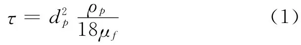
hereρbis the bulk density,4230kg/m3,dpis the dynamic diameter andμfis the flow dynamic viscosity,4.83×10-6kg/(m·s).
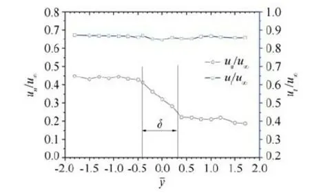
Fig.8 Normal and tangential velocity lines across the oblique shock圖8 跨越斜激波法向與切向速度分布曲線

Table 4 Seeding particle relaxation for oblique shock wave over ramp表4 尖劈斜激波示蹤粒子遲滯特性參數
5 Conclusions
Particle Image Velocimetry was applied to Mach 4.0flows in MMH intermittent wind tunnel of SJTU.Firstly,the measured velocity flowfield atMa=4.0was discussed and the results showed that the free stream flowfield at the nozzle exit was parallel to the nozzle axis and homogeneous as expected from supersonic nozzle theory.Secondly,a ramp flow was measured by PIV and the results were in good agreement with calculated velocities from oblique shock theory.Then the flowfield over a corner was tested and the PIV results showed that the complex flow structures were clearly visible as schileren.Therefore,PIV has proved to be an effective technique for supersonic flow as well as for subsonic flow regimes.However,the PIV algorithm need to be further improved to meet the requirements of complex flow tests.
Acknowledgments:
The support of the Foundation for the Author of the National Science Foundation for Post-doctoral Scientists of China(20100470698)is gratefully acknowledged.
:
[1] MORAITIS C S,RIETHMULLER M L.Particle image displacement velocimetry applied in high speed flows[C].Proc.4th Int.Symp.Appl.of Laser Anemometry to Fluid Dyn,1988.
[2] KOMPENHANS J,HOCKER R.Application of particle image velocimetry to high speed flows[R].Riethmuller,M.L.(Eds.):Particle image displacement velocimetry,VKI Lecture Series,1988.
[3] SCARANO F,VAN Oudheusden B W.Planar velocity measurements of a two-dimensional compressible wake[J].Exp Fluids,2003,34:430-441.
[4] SCHROEDER A,WILLERT C E.Particle Image Velocimetry[J].Topics Appl.Physics,2008,112,429-443.
[5] ELAVARASAN R,KROTHAPALLI A,VENKATAKRISHNAN L,et al.Suppression of self-sustained oscillations in a supersonic impinging jet[J].AIAA Journal,2001,39:2366-2373.
[6] YI S H,HE L,ZHAO Y X,et al.A flow control study of a supersonic mixing layer via NPLS[J].Science China Physics,Mechanics & Astronomy(Science in China Series G),2009,52:2001-2006.
[7] ZHAO Y X,YI S H,TIAN L F,et al.The fractal measurement of experimental images of supersonic turbulent mixing layer[J].Science China Physics,Mechanics &Astronomy (Science in China Series G),2008,51:1134-1143.
[8] BUENO P C,CLEMENS N ,GANAPATHISUBRAMANI B.Cinematographic planar imaging of a Mach 2 shock wave/turbulent boundary layer interaction[R].AIAA 2005-441,2005.
[9] UNALMIS O H,HOU Y X,BUENO P C,et al.PIV investigation of role of boundary layer velocity fluctuations in unsteady shock-induced separation[R].AIAA 2000-2450,2000.
[10]MELLING A.Tracer particles and seeding for particle image velocimetry[J].Measurement Science and Technology,1997,8:1406-1416.
猜你喜歡
《學習方法報》歷史中考版(2023年21期)2023-11-09 07:40:38
小獼猴智力畫刊(2022年9期)2022-11-04 02:31:42
中學生數理化·中考版(2022年11期)2022-02-16 07:01:20
數學小靈通(1-2年級)(2020年9期)2020-10-27 03:24:18
當代貴州(2019年41期)2019-12-13 09:28:56
小哥白尼(趣味科學)(2019年6期)2019-10-10 01:01:50
發明與創新(2016年38期)2016-08-22 03:02:52
太空探索(2016年5期)2016-07-12 15:17:55
中國共青團(2015年7期)2015-12-17 01:24:38
中學生數理化·八年級物理人教版(2014年2期)2014-04-02 08:50:44