Reverse Solution and Parametric Design of the Conjugate Cam Weft Insertion Mechanism Based on VB.NET and UG
2012-02-08 06:57:24CHENJianneng陳建能WANGYingLEIChangyi雷昌毅ZHAOXiongRENGenyong任根勇LINWanhuan林萬煥
CHEN Jian-neng(陳建能),WANG Ying(王 英),LEI Chang-yi(雷昌毅),ZHAO Xiong(趙 雄),REN Gen-yong(任根勇),LIN Wan-huan(林萬煥)
College of Mechanical Engineering and Automation,Zhejiang Sci-Tech University,Hangzhou 310018,China
Introduction
The weft is under active control by the rapier head during the weft insertion process on rapier loom.As a result,there exist few faults of weft insertion,which has high reliability[1].The adaptability of weaving varieties is rather strong,so rapier loom has extensive market in the textile industry.Accompanying with dobby loom or jacquard loom,it can weave senior fabric which has complicated and variable patterns,gorgeous colors and wide width,applying polychrome weft.Weft insertion mechanism is the key working mechanism of rapier loom.Its function is to transform the uniform velocity rotation of the loom's spindle into the rectilinear reciprocating motion of the rapier head,then guide the weft to enter and sequently pass through the shed.Among different kinds of weft insertion mechanisms,the conjugate cam weft insertion mechanism has the best performance,which can be designed flexibly and conveniently[2,3].
Different reed space and texture have different requirements to the weft insertion mechanism of rapier loom.This is mainly reflected on the total stroke of the rapier head and the stroke of the rapier head when the weft is beginning to enter the shed.So there exists the problem of serialized design.As to this problem,domestic enterprises often use the method of plotting or analog design.They seldom design new weft insertion mechanism out of the requirements of the weft insertion technology(kinematic properties).These methods are behindhand in design approaches and low in efficiency[4].The reverse solution method is applied.According to the original requirements of kinematic properties of the weft insertion mechanism,the mathematical model of reverse solution is established.On the foundation of the secondary development tool UGOPEN of Unigraphics(UG)and VB.NET,the parametric design platform which is integrated with the functions of parametric reverse solution,motion simulation,three-dimensional modeling,and virtual assembly is developed.With this platform,the design cycle can be shortened greatly and the design efficiency can be increased.
1 Technological Requirements and Kinematic Curves of the Conjugate Cam Weft Insertion Mechanism of Rapier Loom
In order to make the acceleration of rapier head vary gently when the rapier head hands over the weft,which can realize transferring the weft steadily and release the friction of the rapier head to the edge yarn,the acceleration curve of the rapier head should be similar to an isosceles trapezoid.According to the technological requirements of weft insertion,the acceleration curve of weft insertion mechanism is constructed,as shown in Fig.1[5].When the rotary angle φ of the loom's spindle equals φ1,the rapier head begins to enter the shed.When φ ranges in the section[0,φ1],the rapier head goes forward with variable(positive)acceleration.When φ ranges in the section[φ1,φ2],the rapier head goes forward with constant(positive)acceleration.When φ ranges in the section [φ2,φ3],the rapier head goes forward with variable(negative)deceleration.When φ ranges in the section[φ3,180°],the rapier head goes forward with variable(negative)deceleration.When φ equals 180°,the rapier head reaches the maximal stroke.In the remaining half-cycle[180°,360°],the motion of rapier head is symmetrical to that of the former half-cycle [0°,180°].So the parameters of the weft insertion mechanism include the unilateral total stroke Symaxof the rapier head,technological parameters φ1,φ2,φ3,and positive acceleration h of weft insertion.
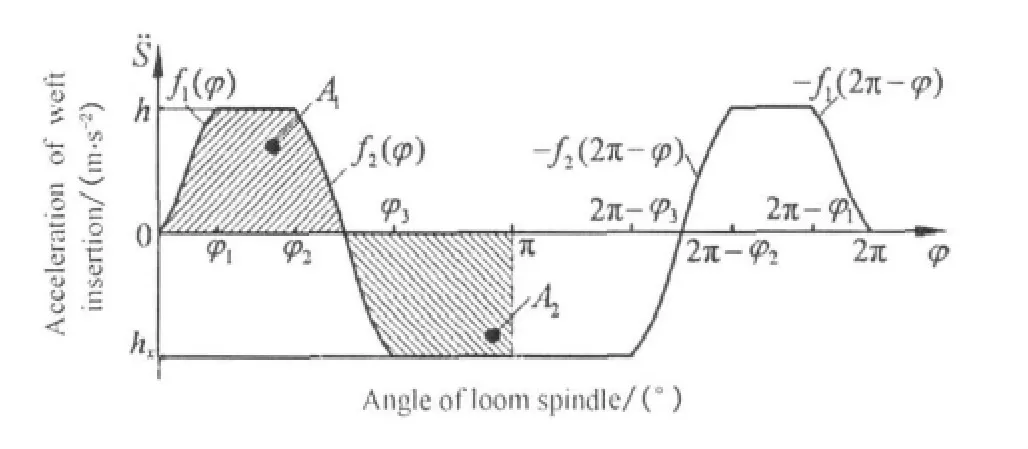
Fig.1 The constructed acceleration curve of weft insertion mechanism
According to the technological parameters and boundary conditions of weft insertion,the values of h,φ1,φ2,φ3,and hxofthe acceleration curve are gotseparately,then the acceleration curve of weft insertion can be determined.The velocity curve can be obtained by using integral to the corresponding acceleration curve,and the displacement curve can be got by using integral to this velocity curve.For example,suppose Symax=1 130 mm,the rapier head enters the shed when φ =70°,reaches the maximal stroke,and then begins to move backward when φ =180°.Then the parameters of the acceleration curve of weft insertion can be solved:φ1=30°,φ2= 75°,φ3= 120°,and h=312.728 m/s2.Its corresponding curves of displacement and velocity are shown in Fig.2.
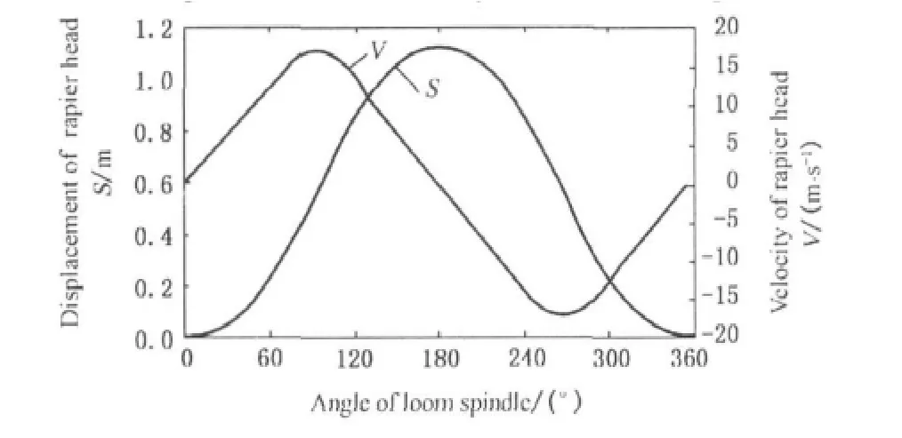
Fig.2 Curves of velocity and displacement of weft insertion mechanism
2 Establishmentofthe Parametric Reverse Solution Modelofthe Conjugate Cam Weft Insertion Mechanism
For the convenience of modeling analysis,the related parameters are listed in Table 1.
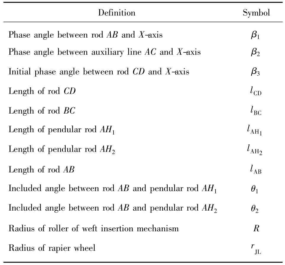
Table 1 Parameters of weft insertion mechanism
The sketch of the conjugate cam weft insertion mechanism is shown in Fig.3.It mainly consists of the conjugate cam 1,rigid angle-shape rod H1AH2,4 bar mechanism ABCD,ordinary gear trains z1,z2,z3,and rapier wheel.The conjugate cam 1 forces the rigid angle-shape rod H1AH2to swing reciprocatingly.The pendular rod AB is fixed with rod H1AH2rigidly,through 4 bar mechanism ABCD.Rod AB drives sector gear 2 which is connected with pendular rod CD rigidly and makes it swing reciprocatingly.Finally after the stroke amplification by ordinary gear trains z1,z2,z3and rapier wheel 3,the rapier belt 4 which meshes with rapier wheel can achieve the rectilinear reciprocating motion[6].
2.1 Transformation of kinematic relation of the gear train
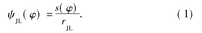
According to section 1,the kinematic characteristics of the rapier head yJL=s(φ)and related technological parameters of the weft insertion mechanism are already known.The angular displacement of the rapier wheel is:
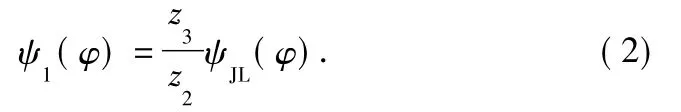
After the amplification by the ordinary gear trains z1,z2,and z3,the angular displacement of gear z1is:
2.2 Establishment of the kinematic equations of the double rocker mechanism
In order to make the model normalized,we choose any point as the origin to set up a coordinate system.
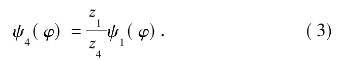
Sector gear z4meshes with gear z1,and their linear velocities on the reference circle are equal,so the angular displacement of the sector gear is:
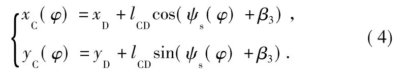
Rod CD is connected with the sector gear rigidly,so the equation of locus of point C is:
In triangle△ABC,according to the law of cosine,we have:
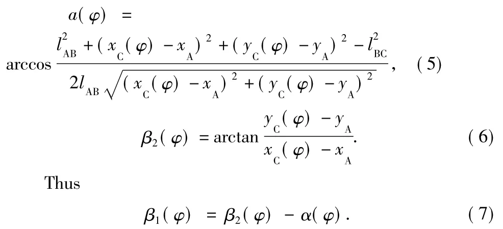
So the equation of locus of point B is:
2.3 Establishment of the profile equation of the conjugate cam
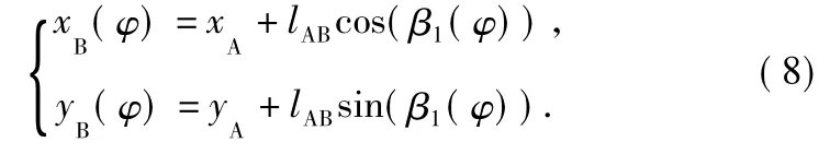
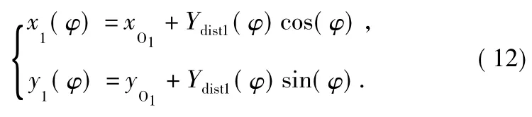
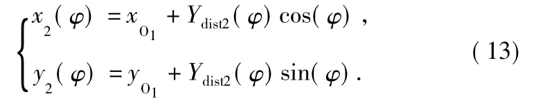
Rod AB is connected with pendular rod H1AH2rigidly,and the parametric equation of the locus of the roller's rotation center H1on pendular rod AH1is:
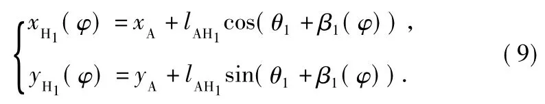
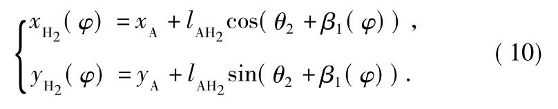
Meanwhile,the equation of locus of H2on pendular rod AH2is:
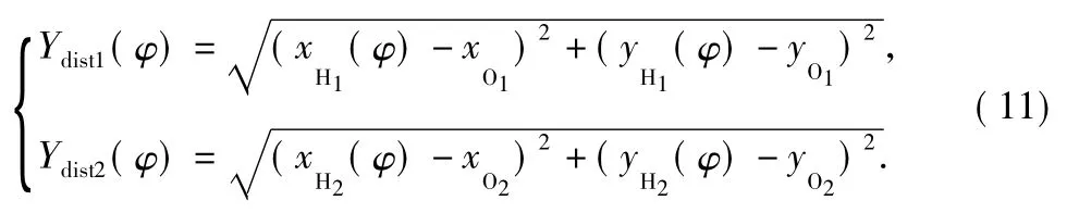
The distances from the theoretical profiles of the master cam and assistant cam to the rotary spindle are:
Meanwhile,the theoretical profile of the assistant cam is:
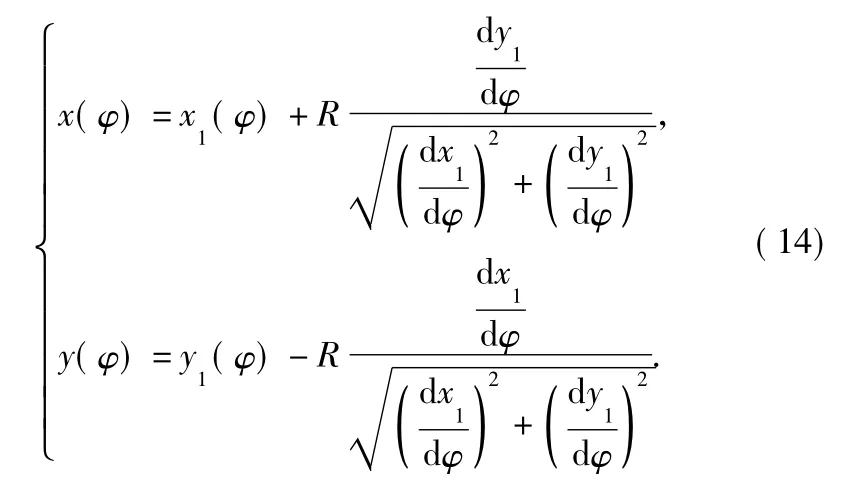
According to the envelope method of the curve family,the actual parametric equation of the profile[7,8]of the master cam is:
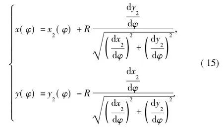
Meanwhile,the actual parametric equation of the profile of the assistant cam is:
3 Establishmentofthe Parametric Design Platform of the Conjugate Cam Weft Insertion Mechanism
According to the mathematical model of reverse solution which is built in section 2,the parameters of weft insertion mechanism and the profile data of the conjugate cam can be obtained by giving technologicalparametersand essential structural parameters applying reverse solution method.Based on VB.NET,the secondary development of UG is conducted.The UG modeling of the conjugate cam is controlled by UGOPEN API order.Besides,other mechanisms are modeled by common parametric method to accomplish parametric design.
3.1 Add visible interface in UG using VB.NET
Add visible interface in UG using VB.NET,its corresponding code is listed in Fig.4.
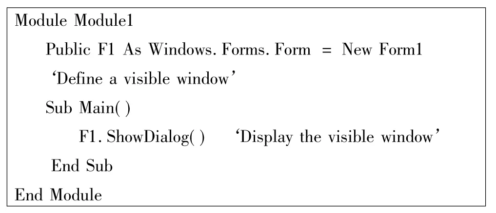
Fig.4 Code of adding visible interface in UG using VB.NET
According to the reverse solution model of weft insertion mechanism,the reverse solution program is compiled in the visible window in UG,as shown in Fig.5.
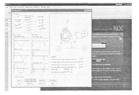
Fig.5 Interface of reverse solution and simulation
3.2 Parametric modeling of the conjugate cam of weft insertion mechanism
According to the reverse solution model of weft insertion,the data of the points on the master cam can be got.Applying VB.NET platform and the artistic spline order of UGOPEN[9,10],build a close curve in UG,then stretch this spline curve,finally the threedimensional model of the needed master cam is built.Add a circular truncated cone using UGOPEN order,similarly,apply the same method of the automatic modeling of the master cam,and build the model of assistant cam.The result is shown in Fig.6.
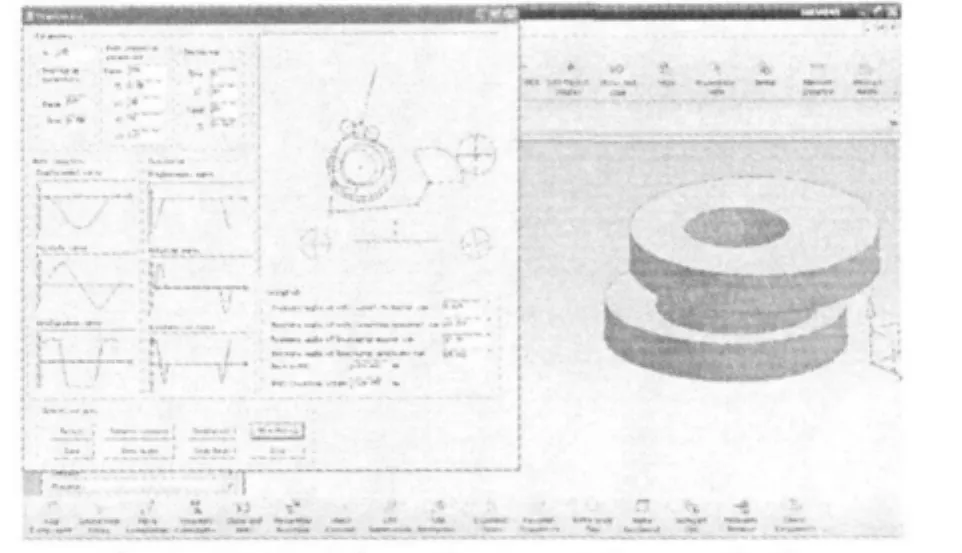
Fig.6 Sketch of the conjugate cam drawn under the control of the compiled program in UG
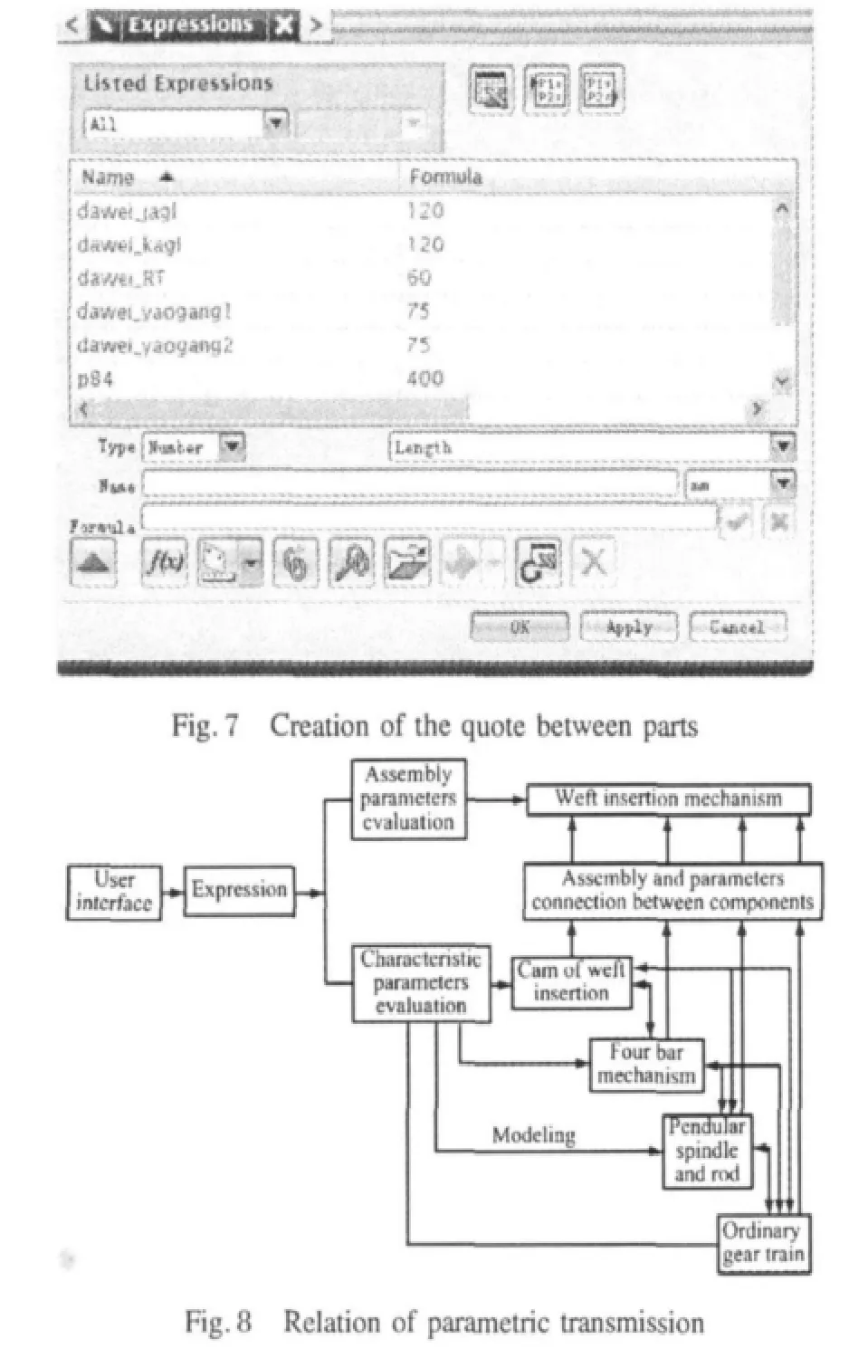
3.3 Parametric design of other parts of the conjugate cam weft insertion mechanism
Except the cam,other parts must be designed under threedimension condition.Use the part design module of UG to build the three-dimensional parametric models rapidly and accurately,then finish the assembly of these parts.Take advantage of the related design method between parts of UG/WAVE,and create the quote of measurement between parts,as shown in Fig.7.The transmission relation of parameters between parts is shown in Fig.8.
Through the VB.NET platform,drive the measurements of the assembly model to finish the parametric design of other parts of the conjugate cam weft insertion mechanism.The code of driving the measurements is shown in Fig.9.
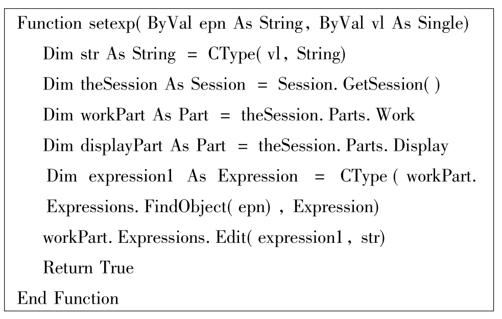
Fig.9 Code of driving the measurements
4 Application of the Parametric Design Platform of the Conjugate Cam Weft Insertion Mechanism
UG software will open automatically as soon as users operate the compiled VB.NET program,as shown in Fig.6.Call the* .dll file which is generated by the program,then the visible interface that we want to create will appear.This interface is precisely the visible interface that we often use in VB6.0.Users only have to choose the needed structural and technological parameters in the interface,then the three-dimensional assembly drawing of the corresponding mechanism can be got.And this function indeed realizes the integration of design,calculation,and modeling.
Input the given parameters,the following parameters can be obtained by reverse solution:transmission ratio of the ordinary gear train r=2.778,rjl=150 mm,β3=75°,lCD=122 mm,lAB=105 mm,lBC=360 mm,lAH1=74 mm,lAH2=74mm,θ1=75°,θ2=180°,R=30 mm.Input the parameters above into the visible interface,enter the simulation interface,and click the“reverse solution”button,as shown in Fig.5.Then click the“UG modeling”button,and the three-dimensional assembly drawing of the conjugate cam weft insertion mechanism can be got,as shown in Fig.10.The processing data of the conjugate cam of the weft insertion mechanism are listed in Table 2.
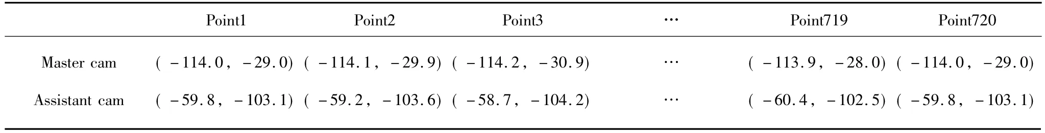
Table 2 Profile data of the conjugate cam of weft insertion mechanism
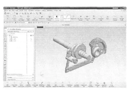
Fig.10 Assembly drawing of the designed weft insertion mechanism
5 Conclusions
(1)It can reflect the demand of design better to calculate the parameters of weft insertion mechanism according to the technological requirements of weft insertion (kinematic properties)by applying reverse solution method.
(2)The established parametric design platform which is integrated with the functions of parametric reverse solution,motion simulation,three-dimensionalmodeling and virtual assembly,provides a convenient platform for the parametric design of weft insertion mechanism.
[1]Zhang X M,Tian K Q,Guo J Y,et al.Study and Development of SeniorRapier Loom [J].Mechanical Management and Development,2007(6):14-15,17.(in Chinese)
[2]Liu Z H.Design and Analysis of New Weft Insertion Mechanism in Rapier Loom[D].Nanjing:Southeast University,2004.(in Chinese)
[3]Zhao X,Xu B,Chen J N,et al.Several Typical Weft Insertion Mechanisms of Rapier Loom and Mechanical Innovation[J].Textile Machinery,2008(2):48-51.(in Chinese)
[4]Zhang Y.Study of the Terry Towel Weaving Device of Shuttleless Towel Loom [D].Shanghai:Donghua University,2007.(in Chinese)
[5]Zhao X,Hu Y L,Lin W H,et al.Establishment and Application of New Weft Insertion Kinematics Curves on Rapier Loom[J].Journal of Zhejiang Sci-Tech University,2010,27(4):556-560.(in Chinese)
[6]Luo J,Xu N Y,He Y,et al.Analysis and Optimization of Cam Weft Insertion Motion in Rapier Loom[J].Melliand-China,2005(6):26-32.(in Chinese)
[7]Ou C J,Yao B,Tian G H.Parametric Design of Oscillate Roll Driven Part Conjugate Cams Mechanism[J].Light Industry Machinery,2010,28(3):48-51.(in Chinese)
[8]Zhang C L,Bai S H.Design of the Conjugate Cam Tightening Weft[J].Journal of Beijing Institute of Technology,2000,20(1):33-36.(in Chinese)
[9]Wu L X.Research of Parameterized Design of Gears and Movement Emulation Analysis Based on UG[D].Beijing:Beijing University of Posts and Telecommunications,2009.
[10]Wang TH,MengG Y.TheResearchofUG Secondary DevelopmentTechnology Based on .NET[J].Modern Manufacturing Technology and Equipment,2010(1):67-68.(in Chinese)
 Journal of Donghua University(English Edition)2012年2期
- Journal of Donghua University(English Edition)的其它文章
- A New Design Method for Variable Digital Filter Based on Field Programmable Gate Array(FPGA)
- Clogging Process Caused by Organic Particle Accumulation and Biofilm Growth in Subsurface Wastewater Infiltration System
- The Usability of Polyoxyethylene Stearate as Lubricant for Sizing Cotton Warp Yarns
- A Stochastic Study on the Wicking Phenomena
- Isothermal Crystallization Behavior of Poly(ethylene terephthalate)/Carbon Black Masterbatch