納米碳纖維載鉑作為質子交換膜燃料電池陽極催化劑
2011-12-11 09:09:56王喜照鄭俊生馬建新
物理化學學報 2011年8期
王喜照 符 蓉 鄭俊生 馬建新
(1同濟大學新能源汽車工程中心,上海201804; 2同濟大學汽車學院,上海201804; 3聯合汽車電子有限公司技術中心,上海201206;4華東理工大學資源與環境工程學院,上海200237)
納米碳纖維載鉑作為質子交換膜燃料電池陽極催化劑
王喜照1,3符 蓉1,4鄭俊生1,2,*馬建新1,2
(1同濟大學新能源汽車工程中心,上海201804;2同濟大學汽車學院,上海201804;3聯合汽車電子有限公司技術中心,上海201206;4華東理工大學資源與環境工程學院,上海200237)
采用化學還原法合成了微結構不同的納米碳纖維(板式、魚骨式、管式)載鉑催化劑(分別記為Pt/p-CNF、Pt/f-CNF、Pt/t-CNF).通過高分辨透射電鏡(HRTEM)和X射線衍射(XRD)等分析技術對催化劑的微觀結構進行了表征,并利用循環伏安(CV)法分析了催化劑的電化學比表面積(ESA).在此基礎上,制備了膜電極(MEA),通過單電池測試了催化劑的電催化性能.結果表明:鉑納米粒子在不同的納米碳載體上表現出不同的粒徑,在板式、魚骨式和管式納米碳纖維上的鉑納米粒子平均粒徑分別為2.4、2.7和2.8 nm.板式納米碳纖維載鉑催化劑作單電池陽極時表現出良好的電催化性能,其對應的最高功率密度可達0.569 W·cm-2,高于魚骨式納米碳纖維載鉑催化劑和管式納米碳纖維載鉑催化劑對應的最高功率密度(分別為0.550和0.496 W·cm-2).同時,也制備了碳黑(Pt/XC-72)載鉑催化劑.相比于Pt/XC-72,納米碳纖維載體上的鉑納米顆粒有較小的粒徑、較好的分散和較高的催化活性,說明納米碳纖維是質子交換膜燃料電池(PEMFCs)催化劑的良好載體.
催化劑;納米碳纖維;鉑納米粒子;催化活性;燃料電池
1 Introduction
Proton exchange membrane fuel cells(PEMFCs)are considered to be one of the most ideal options for energy conservation and environment protection due to their high efficiency and zero emission.However,one of the significant obstacles for the development of PEMFCs is the high cost of noble metals used as electrode catalysts such as Pt.At a low temperature, Pt is an excellent catalyst for hydrogen oxidation reaction (HOR),1but Pt is at a very low level of abundance,resulting in prohibitive cost for the usage of Pt catalyst.In order to improve the efficiency of Pt usage,Pt supported on carbon material provides a practical solution.2-4It is well known that the electrocatalytic activity of Pt particles is associated with the carbon support.5,6Although the underlying mechanisms of the effect on activity are still not well understood,it is suspected that the microstructure and electronic properties of carbon support may be well responsible.
Due to the unique microstructure properties and high electric conductivity,7,8carbon nanofibers(CNFs)have been considered to be promising catalyst support materials.9-12According to the different arrangement of grapheme layers,CNFs can be divided into platelet CNF(p-CNF),tubular CNF(t-CNF),and fish-bone CNF(f-CNF).13The graphene layers of p-CNF are vertical to the fiber axis,and the exposed surface is mainly occupied by edge atoms,while the grapheme layers of t-CNF are parallel to the fiber axis and many basal atoms are exposed. The graphene layers of f-CNF are inclining to the fiber axis, and the ratio of edge atoms to basal atoms can be adjusted by controlling the angle of graphene layers to the fiber axis.It was reported that the microstructure of CNFs can be tailored by controlling the reaction conditions,which made possible to adjust the deposition of and interaction with the metal nanoparticles.14-17Gangeri et al18deposited Pt nanoparticles by incipient wetness impregnation on CNF surface and found that Pt/CNF gave a better performance than that of Pt/XC-72 as anode catalyst.Yuan and Ryu19demonstrated that catalyst supported on CNF showed an improved activity compared to that on carbon nanotubes(CNTs).They believed the improvement in performance was resulted from the specific crystallographic orientations of metal nanoparticles when metal nanoparticles dispersed onthehighlytailoredgraphitenanofibermicrostructures.
In this study,Pt nanoparticles supported on the p-CNF, t-CNF,and f-CNF were synthesized by a chemical reduction method,and their catalytic activities were investigated.Furthermore,Pt nanoparticles supported on carbon black(Pt/XC-72) were also prepared and investigated.In order to evaluate catalysts,membrane electrode assembly(MEA)with an apparent area of 50 cm2was fabricated and tested in a single cell testing platform.
2 Experimental
2.1 Catalyst preparation
CNFs with different structures,i.e.,p-CNF,f-CNF,and t-CNF,were synthesized by catalytic chemical vapor deposition(CCVD)method.Details of CNFs synthesis procedure were described.20Pt nanoparticles supported on the p-CNF, t-CNF,or f-CNF were prepared via an ethylene glycol(EG) chemical reduction method.21In brief,30 mL ethylene glycol, 0.25 g CNF,and 4.2 mL H2PtCl6ethylene glycol solution(with H2PtCl6concentration of 0.077 mol·L-1)were mixed in a 100 mL quartz beaker.The mixture was ultrasonicated and stirred for 4 h.Then,2 mL NaOH ethylene glycol solution(with NaOH concentration of 0.5 mol·L-1)was added.The mixture was stirred and refluxed at a temperature of 120°C for 3 h.After that,the pH value of the mixture adjusted to 3 by adding 5 mol· L-1HCl.The resultant was washed and dried in a vacuum oven at 70°C for 24 h.Finally,the required catalyst with a nominal Pt loading of 40%(w)on CNF was obtained.Pt/XC-72 was also prepared in the same way.The as-prepared catalysts were markedas Pt/p-CNF,Pt/f-CNF,andPt/t-CNF,respectively.
2.2 Physical characterization
The mass fraction of Pt in Pt/C catalyst was detected by inductively coupled plasma(ICP,7500A,Agilent,USA).The morphologies of catalyst were characterized by high resolution transmissionelectronmicroscope(HRTEM,JEOL TEM 2010),which was operated at 200 kV.The X-ray diffraction (XRD)patterns of crystalline phase were collected on a D/max 2550 powder diffractometer using Cu Kαradiation.The working voltage was 40 kV,and the current was 40 mA.The intensity data were collected in a 2θ range of 10°to 100°with a scan rate of 0.02(°)·min-1.
2.3 Preparation and modification of electrode
Electrochemical measurements were performed in a CHI 730C electrochemical workstation (CHI Instrument,Inc., USA)in a 0.5 mol·L-1HClO4solution.The electrochemical surface area(ESA)was measured by cyclic voltammetry(CV) method.The working electrode was glassy carbon(GC,5 mm in diameter)coated with as-prepared catalyst.A saturated calomel reference electrode(SCE)was used for all electrochemical measurements.A Pt clump was used as the counter electrode. The working electrode was prepared according to the following procedures.The as-prepared catalyst was dispersed ultrasonically in a solution of Nafion(Dupont)and methanol to obtain a homogenous black suspension with a concentration of 2 g·L-1.Then 10 μL of the mixture was pipetted onto the surface of glassy carbon(GC)electrode which was polished to a mirror finish with 0.05 μm of alumina pastes.After drying,the working electrode with a Pt content of 0.04 mg·cm-2on the surface of GC was ready.Before testing,the electrolyte was bubbled with nitrogen for 30 min,and the current-potential curve was recorded in the presence of nitrogen.The scan rate was 0.1 V·s-1with the scanning potential range of 1.0 to-0.2 V(vs SCE).
2.4 Fabrication of MEA and single cell test
MEA fabricated by catalyst coated in membrane(CCM) method.Appropriate amounts of catalyst powder were mixed with a solution of Nafion(the mass ratio was 5%)and isopropyl alcohol,then the mixture was dispersed ultrasonically to form a homogeneous ink(the mass ratio of catalyst to Nafion was 3:1).After that,the catalyst ink was sprayed onto a 50 cm2of Nafion membrane(NR212).The other side of membrane was sprayed in the same way.Nafion membrane with catalyst on both sides was then sandwiched between two gas diffusion layers(Toray TGP-H-090).Four pieces of MEA were fabricated with prepared Pt/p-CNF,Pt/f-CNF,Pt/t-CNF,and Pt/XC-72 as anode catalyst and commercial Pt/C(Johnson Matthey,HiSPEC 4000)as cathode catalyst.Both sides of the Pt loading were 0.4 mg·cm-2for each MEA.
The measurement was carried out in a single cell testing platform.The single cell was fed by pure hydrogen and compressed air with the pressure of 80 kPa in both inlets.The stechiometry coefficients of hydrogen and air were 1.3 and 2.5, and the flow rate was adjusted according to the current by a mass flow controller automatically.Before entering the cell,hydrogen and air were humidified in a bubbling humidifier.The cell was operated at 80°C,which was controlled by a thermostatic water bath.After a break-in period,polarization curve was recorded.
3 Results and discussion
3.1 Textural properties of CNFs and XC-72
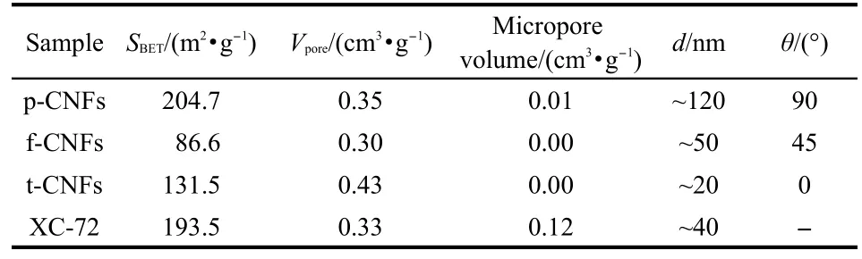
Table 1 Textural properties of CNFs and XC-72
Table 1 shows the textural properties of CNFs and XC-72. The specific surface areas(S)of CNFs are in the range of 86.6-204.7 m2·g-1.The specific surface area of p-CNF is larger than that of f-CNF and t-CNF because the graphene layers of p-CNF are vertical to the fiber axis and some rough surfaces are formed.The surface area of XC-72 is 193.5 m2·g-1,larger than those of t-CNF and f-CNF.Table 1 also shows that the pore volumes of the four supports are close,but the micropore volumes are much different.The micropores are very small and can be neglected and the mesopores are the dominant pore structure for all CNFs.But for XC-72,the micropore volume is 0.12 cm3·g-1.The mesopores can promote the diffusion,and this is a CNF?s distinctive advantage for their application in electrocatalysis because the mass transportation is expedited.
3.2 Physico-chemical properties of catalysts
The ICP result demonstrates that the mass fractions of Pt for all the prepared catalyst are close to the theoretical values with the mass ratio of 40%.HRTEM micrographs of CNFs are displayed in Fig.1.It is found that the graphene layers of p-CNF are vertical to the fiber axis,while those of t-CNF are parallel to the fiber axis,and the graphene layers of f-CNF are inclining to the fiber axis.HRTEM micrographs of Pt/CNFs and Pt/ XC-72 are displayed in Fig.2.Generally,metal nanoparticles show no tendency to aggregate and are good dispersed on the surface of CNFs and XC-72.The Pt particle sizes are obtained by measuring the nanoparticles on HRTEM images.Nearly 300 nanoparticles in random regions are measured to ensure statistically significant representation of the nanoparticles sizes.The corresponding histograms of size distribution are shown in Fig.3,which reveals that the particle size distribution for each catalyst is rather narrow and exhibits the features of Gaussian distribution.The average size for each catalyst is calculated.It can be found that Pt particle size changes with the changing of support.The average sizes of Pt nanoparticles on p-CNF,f-CNF,and t-CNF are 2.4,2.7,and 2.8 nm,respective-ly.All of the sizes are smaller than that of Pt nanoparticles on XC-72(3.1 nm).CNFs have highly tailored graphite nanofiber structures,while XC-72 is made of amorphous carbon.This may be a reason that most of Pt nanoparticles on CNFs are smaller than those on XC-72.22,23CNFs expose many edge atoms,and these edge atoms contain large quantity ruptured chemical bonds,which may influence the Pt particle size.24Compared with f-CNF and t-CNF,p-CNF has a higher ratio of edge atoms to basal atoms,13and this may contribute to the smaller particle size on p-CNF than those on f-CNF and t-CNF.
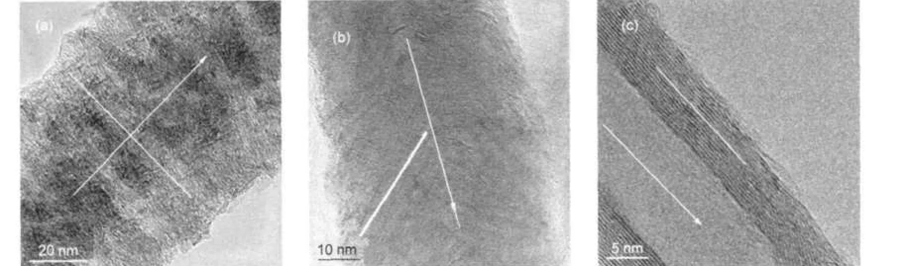
Fig.1 TEM images of p-CNF(a),f-CNF(b),and t-CNF(c)
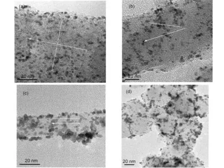
Fig.2 HRTEM images of Pt/p-CNF(a),Pt/f-CNF(b),Pt/t-CNF(c),and Pt/XC-72(d)
XRD patterns of Pt/CNFs and Pt/XC-72 are presented in Fig.4.The first peak at 2θ near 26.4°can be attributed to the graphite structure of supports.The major peaks locate at 2θ of 39.7°,46.2°,67.4°,and 81.2°are ascribed to Pt(111),Pt(200),Pt(220),and Pt(311)characteristic diffraction peaks,respectively.These characteristic diffraction peaks agree well with the report.25The fitted Pt(220)plane is isolated from the diffraction peaks of carbon support and is used to calculate the metal particle size according to the Scherrer formula.26The calculation results are listed in Table 2.It can be found that the XRD results are consistent with those obtained from Fig.2.
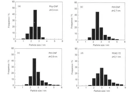
Fig.3 Histograms of Pt particle size distribution for Pt/p-CNF(a),Pt/f-CNF(b),Pt/t-CNF(c),and Pt/XC-72(d)d:average size
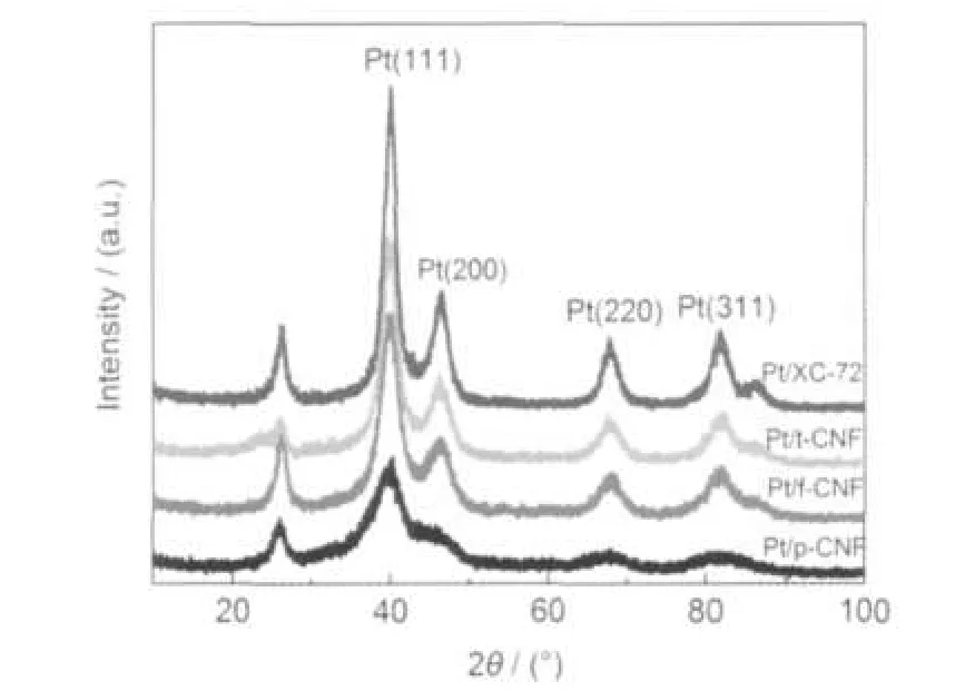
Fig.4 XRD patterns of Pt/p-CNF,Pt/f-CNF,Pt/t-CNF,and Pt/XC-72
Fig.5 presents the CV curves of Pt/CNFs and Pt/XC-72.The results exhibit the typical behavior regarding the hydrogen and oxide regions for Pt.27,28As shown in Fig.5,well-defined hydrogen adsorption/desorption characteristics are observed for the four kinds of as-prepared catalyst.A weak adsorption peak in the potential range from 0.05 to-0.1 V and a strong adsorption peak located between-0.1 and-0.2 V are observed during the negative-going potential scan,assigned to weakly andstrongly bonded hydrogen adatoms,respectively.The corresponding desorption peaks are observed in the reverse potential scan.The integrated charge in the hydrogen absorption region of CV curve is used to calculate the electrochemical surface area(ESA),which representing the intrinsic electrocatalytic activity of a catalyst.Based on a monolayer hydrogen adsorption charge of 0.21 mC·cm-2on polycrystalline Pt and the integrated charge in the hydrogen absorption region of CV curve,29the ESA can be calculated.Furthermore,Based on that Pt nanoparticle is spherical structure,the chemical surface area (CSA)and the Pt utilization efficiency are also calculated using the following equations:
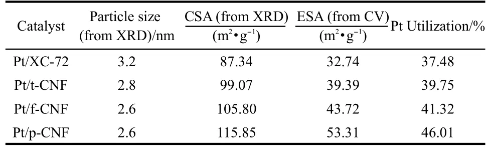
Table 2 Comparison of particle size,electrochemical surface area(ESA),chemical surface area(CSA),and Pt utilization of Pt/ p-CNF,Pt/f-CNF,Pt/t-CNF,and Pt/XC-72
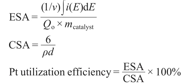
where v is the linear potential scan rate(V·s-1),i is the current (A),E is the electrode potential(V),mcatalystis the mass of cata-lyst deposited on the electrode(8 μg),and Qois the charge involved during the adsorption of a monolayer of atomic hydrogen on a polyoriented platinum surface(0.21 mC·cm-2).ρ represents Pt density(21.4 g·cm-3),and d is the average size of Pt obtained from XRD analysis.The corresponding ESA,CSA, and Pt utilization efficiency are summarized in Table 2.It can be seen that the ESA increases with the decreases of Pt particle size.The ESA for Pt/p-CNF is 53.3 m2·g-1,which is much larger than those for Pt/f-CNF(43.7 m2·g-1)and Pt/t-CNF(39.4 m2·g-1),mainly resulting from the small Pt particle size.The Pt utilization for Pt/p-CNF is 45.6%,which is higher than that for Pt/f-CNF(42.1%)and Pt/t-CNF(39.3%),this may contribute to a better PEMFC performance.
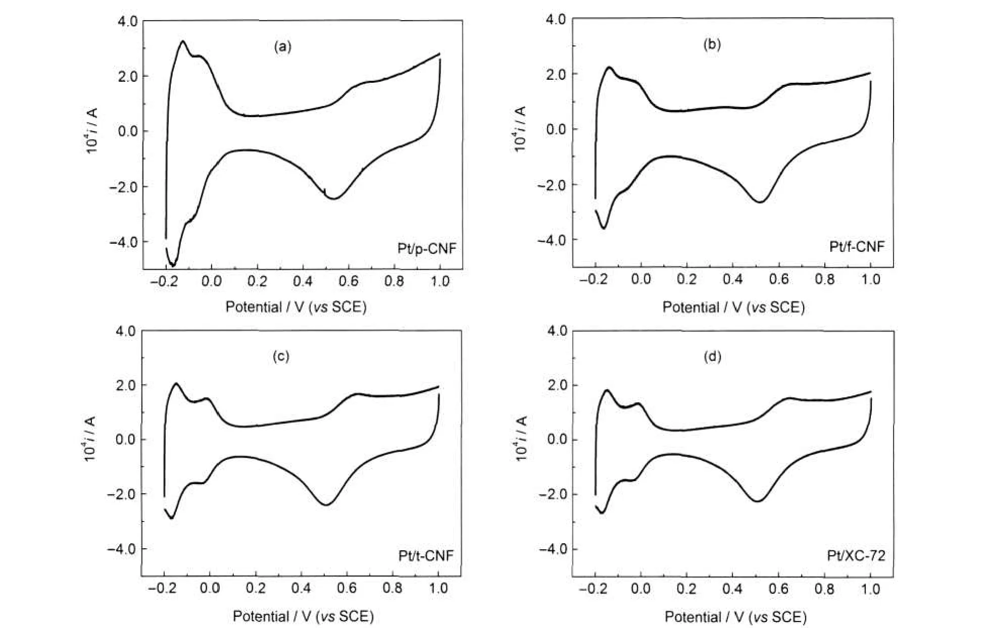
Fig.5 Cyclic voltammetric analysis of Pt/p-CNF,Pt/f-CNF,Pt/t-CNF,and Pt/XC-72 in 0.5 mol·L-1HClO4solution saturated by nitrogen at a scan rate of 0.1 V·s-1
3.3 Performance of PEMFC
Fig.6 shows the polarization curves of single cell with the as-prepared catalysts as anode catalysts.It can be observed from Fig.6 that the open-circuit potentials,for all the catalysts samples,are almost kept at high level of 0.96 V regardless of the difference of support.All the current densities decrease with the increasing of the potential over the whole current density region.Pt/p-CNF gives the best performance in the high current density region,indicating the highest electrocatalytic activity.The maximum power density for Pt/p-CNF is 0.569 W·cm-2,which is higher than those for Pt/f-CNF(0.550 W· cm-2)and Pt/t-CNF(0.496 W·cm-2).This may be the reason that the special mesopore structure of p-CNF,a larger ESA and a higher Pt utilization efficiency of Pt/p-CNF.
4 Conclusions
Pt/p-CNF,Pt/f-CNF,and Pt/t-CNF were synthesized by a chemical reduction method.The structure of support is demonstrated to be the crucial factors influencing the Pt particle size and the catalytic activity for HOR.The maximum power density is 0.569 W·cm-2for Pt/p-CNF,which is higher than those observed for Pt/f-CNF(0.550 W·cm-2)and Pt/t-CNF(0.496 W·cm-2).Furthermore,it is found that Pt nanoparticles supported on CNFs has been proven to possess smaller particle size than those on XC-72,and this proved that CNFs could be an efficient electrocatalyst support for PEMFCs.
1 Arico,A.S.;Srinivasan,S.;Antonucci,V.Fuel Cells 2001,1,133.
2 Yu,J.S.;Kang,S.;Yoon,S.B.;Chai,G.S.J.Am.Chem.Soc. 2002,124,9382.
3 Chai,G.S.;Shin,I.S.;Yu,J.S.Adv.Mater.2004,16,2057.
4 Fang,B.;Kim,M.S.;Yu,J.S.Appl.Catal.B-Environ.2008,84, 100.
5 Dicks,A.J.Power Sources 2006,156,128.
6 Kong,K.;Choi,Y.;Ryu,B.;Lee,J.;Chang,H.Mater.Sci.Eng.C 2006,26,1207.
7 Park,C.;Baker,R.J.Phys.Chem.B 1999,103,2453.
8 Steigerwalt,E.S.;Deluga,G.A.;Cliffel,D.E.;Lukehart,C.M. J.Phys.Chem.B 2001,105,8097.
9 Rodriguez,N.M.;Chambers,A.;Baker,R.Langmuir 1995,11, 3862.
10 Sun,X.;Li,R.;Villers,D.;Dodelet,J.P.;Desilets,S.Chem. Phys.Lett.2003,379,99.
11 Salgado,J.R.C.;Antolini,E.;Gonzalez,E.R.J.Power Sources 2004,138,56.
12 Francisco,A.;Oscar,M.;María,J.;Rafael,M.;Ana,L.;José,S.; Enrique,H.;Antonio,A.Electrochem.Commun.2009,11,1081.
13 Zheng,J.S.;Zhang,X.S.;Li,P.;Zhou,X.G.;Yuan,W.K. Catal.Today 2008,131,270.
14 Calvillo,L.;Lázaro,M.J.;Suelves,I.;Echegoyen,Y.;Bordejé, E.G.;Moliner,R.;Nanosci,J.Nanotechnology 2009,20,1.
15 Steigerwalt,E.S.;Deluga,G.A.;Lukehart,C.M.J.Phys.Chem. B 2002,106,760.
16 Antolini,E.Appl.Catal.B 2009,88,1.
17 Zheng,J.S.;Wang,X.Z.;Qiao,J.L.;Yang,D.J.;Li,B.;Li,P.; Lv,H.;Ma,J.X.Electrochem.Commun.2010,12,27.
18 Gangeri,M.;Centi,G.;La Malfa,A.;Perathoner,S.;Vieira,R.; Pham-Huu,C.;Ledoux,M.J.Catal.Today 2005,102,50.
19 Yuan,F.;Ryu,H.Nanotechnology 2004,15,596.
20 Zheng,J.S.;Zhang,X.S.;Li,P.;Zhu,J.;Zhou,X.G.;Yuan,W. K.Electrochem.Commun.2007,9,895.
21 Li,B.;Qiao,J.L.;Zheng,J.S.;Yang,D.J.;Ma,J.X.Int.J. Hydrog.Energy 2009,34,5144.
22 Zheng,J.S.Microstructure Effect of Carbon Nanofibers on Electrocatalysis:Oxygen Reduction Properties on Cathode.Ph. D.Dissertation,East China University of Science and Technology,Shanghai,2008.
23 He.Z.B.;Chen,J.H.;Liu,D.Y.;Zhou,H.H.;Kuang,Y.F. Diamond Relat.Mater.2004,13,1764.
24 Augustine,R.L.Heterogeneous Catalysis for the Synthetic Chemist;Marcel Dekker:New York,1996;p 170.
25 Li,W.Z.;Liang,H.H.;Zhou,W.J.;Qiu,J.H.;Zhou,Z.H.;Sun, G.Q.;Xin,Q.J.Phys.Chem.B 2003,107,6292.
26 Radmilovic,V.;Gasteiger,H.A.;Ross,P.N.J.Catal.1995,154, 98.
27 Perez,J.;Gonzalez,E.R.;Ticianelli,E.A.Electrochim.Acta 1998,44,1329.
28 Lima,F.H.B.;Ticianelli,E.A.Electrochim.Acta 2004,49,4091.
29 Liu,Z.L.;Lee,J.Y.;Han,M.;Chen,W.X.;Gan,L.M.J.Mater. Chem.2002,12,2453.
March 4,2011;Revised:May 12,2011;Published on Web:June 16,2011.
Platinum Nanoparticles Supported on Carbon Nanofibers as Anode Electrocatalysts for Proton Exchange Membrane Fuel Cells
WANG Xi-Zhao1,3FU Rong1,4ZHENG Jun-Sheng1,2,*Ma Jian-Xin1,2
(1Clean Energy Automotive Engineering Center,Tongji University,Shanghai,201804,P.R.China;2School of Automotive Studies, Tongji University,Shanghai,201804,P.R.China;3Technical Center,United Automotive Electronic Systems Co.,Ltd.,Shanghai, 201206,P.R.China;4School of Resource and Environment Engineering,East China University of Science and Technology, Shanghai,200237,P.R.China)
Pt nanoparticles supported on carbon nanofibers(Pt/CNFs)with different microstructure,i.e., platelet CNF(Pt/p-CNF),fish-bone CNF(Pt/f-CNF),and tubular CNF(Pt/t-CNF)were synthesized by a chemical reduction method.X-ray diffraction(XRD)and high resolution transmission electron microscope (HRTEM)were applied to characterize the structure of the as-prepared catalysts.The electrochemical surface area(ESA)was studied by cyclic voltammetry(CV).Membrane electrode assemblies(MEAs)with the as-prepared catalysts were fabricated and tested.We found that Pt nanoparticles showed different particle size and dispersion on the three kinds of CNF supports and the mean size of the Pt nanoparticles on p-CNF,f-CNF,and t-CNF was 2.4,2.7,and 2.8 nm,respectively.Single cell testing indicated that the cell with Pt/p-CNF as the anode catalyst gave better performance compared to Pt/f-CNF and Pt/t-CNF. The maximum power density was 0.569 W·cm-2for Pt/p-CNF,which was higher than that for Pt/f-CNF (0.550 W·cm-2)and Pt/t-CNF(0.496 W·cm-2).Furthermore,Pt nanoparticles supported on carbon black (Pt/XC-72)were also prepared.Pt nanoparticles supported on CNFs have been shown to have a smaller particle size and better dispersion than those on XC-72,and this proves that CNFs can be an efficient electrocatalyst support for proton exchange membrane fuel cells(PEMFCs).
Catalyst;Carbon nanofiber;Pt nanoparticles;Catalytic activity;Fuel cell
?Corresponding author.Email:jszheng@tongji.edu.cn;Tel:+86-21-69583891;Fax:+86-21-69589121.
The project was supported by the National Natural Science Foundation of China(21006073),Shanghai Rising-Star Program,China(11QA1407200), Shanghai LeadingAcademic Discipline Project,China(B303)and Open-Project Program of the State Key Laboratory of Chemical Engineering, China(SKL-ChE-08C07).
國家自然科學基金(21006073)、上海市青年科技啟明星計劃(11QA1407200)、上海市重點學科(B303)和化學工程聯合國家重點實驗室開放基金(SKL-ChE-08C07)資助項目
O643
猜你喜歡
國家教育行政學院學報(2022年9期)2022-10-10 10:02:28
少先隊活動(2021年5期)2021-07-22 09:00:02
家庭影院技術(2020年11期)2020-12-28 01:22:42
上海建材(2019年4期)2019-05-21 03:13:02
石油石化綠色低碳(2019年6期)2019-02-13 09:39:01
纖維復合材料(2018年4期)2018-04-28 08:45:28
纖維復合材料(2018年3期)2018-04-25 07:22:58
中國塑料(2016年6期)2016-06-27 06:34:16
浙江大學學報(工學版)(2016年11期)2016-06-05 09:21:04
Coco薇(2016年2期)2016-03-22 02:45:06

- 物理化學學報的其它文章
- Micellization Behavior of an Amphiphilic Drug Promethazine Hydrochloride-Surfactant System in an Aqueous Medium
- Synthesis of a Novel Thiadiazine Derivative and Electrochemical Properties for Pb2+Transfer across Water/1,2-Dichloroethane Interface
- YLuAG:Ce粉體的發光及閃爍特征:制備方法及缺陷效應
- 一種可作為FCC基質的新型改性鎂鋁尖晶石材料
- 乙烯基噻吩共軛螺噁嗪化合物的密度泛函理論研究
- 用于單分子動力學實驗的微流控混合器