Uplink Power Control for MIMO-OFDMA Cellular Systems
2011-06-19 11:09:56RongzhenYangandHujunYin
ZTE Communications 2011年4期
Rongzhen Yang and Hujun Yin
(1.Intel China Corp.,Shanghai200241,P.R.China;
2.Intel Corp.,2200 Mission College Blvd,CA 95054-1549,U.S.A.)
Abstract:In this paper,we propose a novel uplink power control algorithm,SMST,for multiple-input multiple-output orthogonal frequency-division multiple access(MIMO-OFDMA).We perform an extensive system-level simulation to compare different uplink power controlalgorithms,including the FPC adopted in 3GPPLTEand LTE-Advanced.Simulations show that SMSTadopted in IEEE 802.16m outperforms other algorithms in terms of spectral efficiency,cell-edge performance,interference control,and trade-off control between sector-accumulated throughput and cell-edge user throughput.The SMSTperformance gain over FPCcan be more than 40%.
Keyw ords:uplink power control;inter-cellinterference;OFDMA;MIMO
1 Introduction
U plink power control is a critical feature of CDMA cellular systems.It is used to alleviate the near-far problem caused by intracell interference.The new generation of broadband wireless technologies,including WiMAXand LTE,are designed to provide higher bandwidth,higher peak throughput,and higher spectralefficiency[1],[2].These wireless technologies are based on orthogonalfrequency-division multiple access(OFDMA),in which all the uplink transmissions are orthogonal within one cell[3].Therefore,intracell interference is minimal compared with technologies based on 3G CDMA.
Fourth-generation WiMAXand LTE wireless standards are designed to support up to 20 MHz channel bandwidth,high-order 4×2 and 4×4 multiple-input multiple-output(MIMO),and aggressive frequency reuse(reuse 1)to improve spectralefficiency and user throughput.Especially for cell-edge users,intercell interference is a significant problem caused by aggressive frequency reuse.Uplink power control is an important mechanism for controlling intercell interference and improving cell-edge user experience(UE),even in broadband wireless systems based on OFDMA[4]-[7].As opposed to 3G,where closed-loop power control is typically used to control both intracell and intercell interference,the main objective of uplink power control in OFDMA-based systems is to control intercell interference[8],[9].
In this paper,we investigate control of uplink transmit power in order to maximize sector and cell-edge spectral efficiency.These are essential parameters for next-generation broadband wireless systems[10]-[13].A simplified maximum-sector throughput(SMST)algorithm is proposed that maximizes sector throughput by adjusting uplink transmit power.
2 Uplink Power Control Mechanisms
2.1 Background
Power control has been studied extensively since the introduction of cellular systems.A power-control mechanism can be closed-loop power control(CLPC),open-loop power control(OLPC),or CLPC-OLPC combined power control.In CLPC,power control is centralized at the base station(BS).The mobile station(MS)provides feedback on link quality,and the BScalculates the uplink transmit power level for the MSand instructs the MSto transmit at that level.In OLPC,the MSmeasures link quality and calculates the uplink transmit power level(based on predetermined equations)in a distributed manner.The BSmay influence the MSby adjusting certain parameters in the equation,but the BSdoes not directly controlthe MS transmit power.
2.1.1 CLPC
In a CDMA system,CLPC allows commands to be sent from the BSso that power can be quickly adjusted.In an OFDMA system,intracell interference is not significant,so adaptive modulation and coding(AMC)and hybrid automatic repeat request(HARQ)are used to provide fast link adaptation for the data channel.CLPC is mainly used for fixed-rate control channel when channel fading exceeds the power margin.In CLPC in the BS,the received signalquality is monitored and power-adjustment commands are sent.
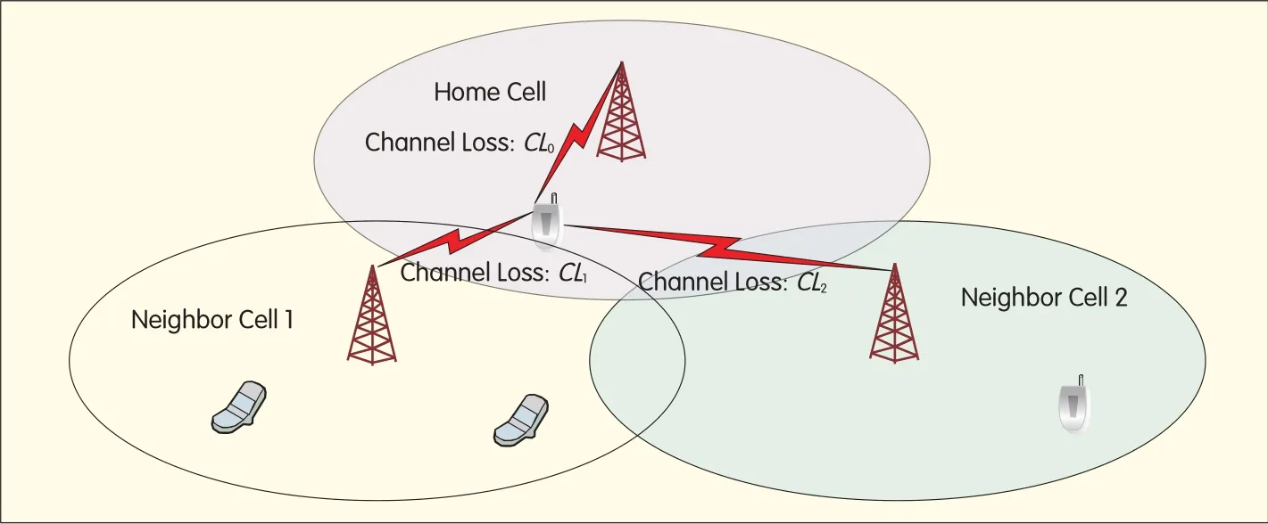
▲Figure 1.Uplink interference for one MSin a typical MIMO-OFDMAcellular system.
2.1.2 OLPC
OLPC is mainly implemented in the MS.The MSmeasures downlink signal status,compensates the uplink path loss,and controls interference to neighboring BSs.With OLPC,the MS needs some static/semi-static configuration parameters to be signaled by the BSand does not require short-term inputs.This saves overall signaling overhead.
2.1.3 CLPC-OLPC Combined Power Control
In current 4G wireless standards,both CLPC and OLPC are combined to balance flexibility with signaling overhead.OLPC is mostly used to save signaling overhead.
2.2 Uplink Power Control Algorithms
Depending on the goal of the power control mechanism,the uplink power-control algorithm can be based on signal-to-noise ratio(SNR),signal-to-interference plus noise ratio(SINR),or Internet of things(IoT).
2.2.1 SNR-Based Algorithm
The goal of an SNR-based algorithm is to maintain the desired received signal strength in the BS.An SNR-based algorithm does not take into consideration the uplink-received interference power level.This type of algorithm is simple to implement and always convergent.Fractional power control(FPC)in LTEis an SNR-based algorithm.
2.2.2 SINR-Based Algorithm
The goal of an SINR-based algorithm is to maintain the desired received SINRlevel in the BSwhile taking into account the uplink interference power level.SMSTused in IEEE 802.16m is an SINR-based algorithm that defines the desired received SINRgoal for each MSand takes into account the measured downlink signal-to-interference ratio(SIR),uplink MIMO mode,and BSantenna configuration.
2.2.3 IoT-Based algorithm
The goal of an IoT-based algorithm is to maintain the desired uplink interference level in the BS.In general,an IoT-based algorithm can stabilize the interference level in the uplink to help control interference and modulation-coding-scheme(MCS)level estimation.
3 Maximizing Throughput with Power Control
3.1 System Modeling
Fig.1 shows an uplink interference model for one MSin a typical MIMO-OFDMAcellular system.
At any time,the MSuses the uplink to transmit to its home BSand causes interference to neighboring BSs.To simplify the analysis,simple input simple output(SISO)is assumed,and the parameters for the model are
?Ps:The MSuplink transmission power(linear)of one data subcarrier at a given time;
?i:cell index.i=0 is the home BS,and i=1-N is the neighboring BSs;
?CLi:The instantaneous channel loss(linear)from MStransmitter to one receiving antenna of a BS;
?NIi:The noise-plus-interference level(linear)per subcarrier at a BS receiving antenna.
3.2 Maximum Throughput Criteria
The aggregated cell throughput is

If we assume that all BSs occupy the same bandwidth,(1)can be modified:
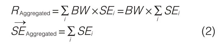
For uplink power control of each MS,aggregated spectrum efficiency SEis prioritized as the target of the algorithm,which can be expressed as
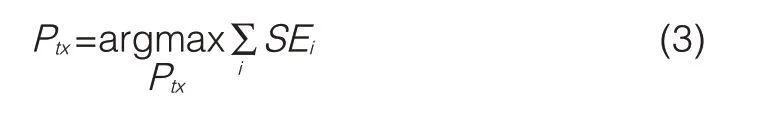
To solve(3)for each MS,the following process is used:1)PSis the transmission power of one subcarrier that is initialized to 0
2)A power increase,ΔPS,is assumed in order to calculate
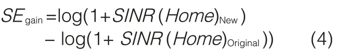
i)SEgain:as the power increases,this is the spectrum efficiency gain that the MScan achieve in the home BSon the subcarrier.
ii)SEloss:as the power increases,this is the spectrum efficiency loss the MS inflicts on the neighboring BSs on the subcarrier.
3)SEgainand SElossare compared
i)If SEgain>SEloss,PS=PS+ΔPS,go back to 2
ii)If SEgain≤SEloss,then the PSis optimum on the subcarrier for the MS.
This process is used to evaluate the SEgainand SElossfor each power increase ofΔPS.
At any time,when a power increase ofΔPSis assumed,the SEgainof the MS on the subcarrier can be obtained by
where

Combining(4),(5),and(6),SEgaincan be expressed as
The SElosson the subcarrier in one neighbor BSi(i=1-N)can be expressed as SINR(i)New=
Siis the received signal power on the subcarrier of BSi,andΔIi= is the increased inference power caused byΔPS.
From(8),the total SEloss on the subcarrier in all neighbor BSs can be expressed as
Therefore,the optimum power on the subcarrier can be calculated by increasing PSof the subcarrier byΔPSsteps from 0 untilthe SEgainand SElosson this subcarrier no longer satisfies
If the MSis assigned resources for uplink transmission by the BS,optimal transmission power for all assigned uplink subcarriers can be calculated in order to achieve the overall optimum cellthroughput.This algorithm is called the maximum sector throughput(MST)algorithm.
4 Simplified Maximum Sector Throughput Algorithm
4.1 MSTAlgorithm Simplified Form
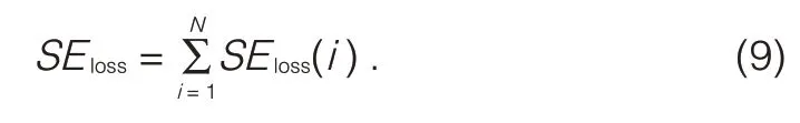
The MSTalgorithm is only useful in theory and is impossible to be implemented in practice.The algorithm requires the home BSor MSto accurately know the received signal power and interference power on all neighbor BSs on each subcarrier at the time of uplink transmission.Making some simple assumptions,we developed a practical SMSTalgorithm.First,we modeled one virtual neighbor BS(or sector)that accounts for all interference impact on SEloss(Fig.2).
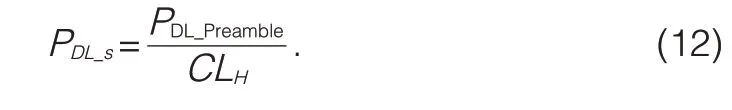
We assume that all BSs have the same downlink transmission power level.The total downlink reference interference power from the virtual BS to the MSis
▲Figure 2.Uplink interference from one MS.
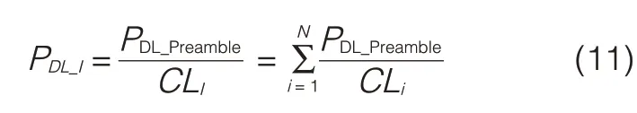
where PDL_Preambleis the downlink preamble power used as the reference signal to measure downlink path loss,and CLIis the virtual downlink path loss.The downlink reference signal power of the MSis
Downlink SIRcan be measured as,so that

The SEgaincan be expressed as
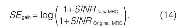
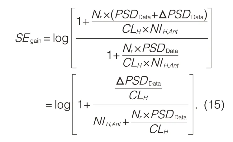
One virtual neighbor modelis used,and one MSkeeps the same transmission power spectral density(PSD)for all data tones(PSDData).Only one transmission stream is used,and there are Nr receiving antennas at the BS(an MRC receiver is assumed).
It is further assumed that each receiving antenna on the BSsuffers similar noise and interference level NIH,Ant,and the path loss from transmission antenna to each receiving antenna is similar to CLH,then(14)can be re-written as
Similarly,the new SElosson the virtual neighbor BScan be expressed as
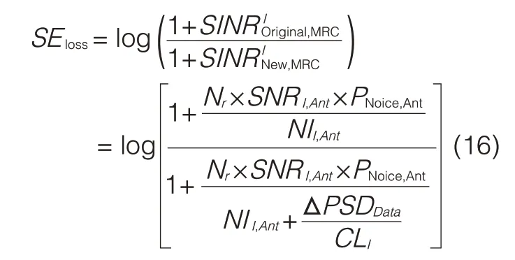
where NII,Ant,is the noise plus interference for each antenna on the virtual BS,PNoice,Ant,is the white noise for each antenna on the virtual BS,SNRI,Antis the average SNRlevel for each antenna on the virtual BS,and SNRI,Ant×PNoise,Ant,is used to estimate received signal PSD for each antenna on the virtual BS.
The optimum overall SEcan be obtained when the following condition is met:
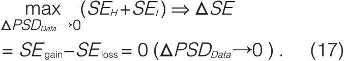
From(13),(15),(16)and(17),we canderive
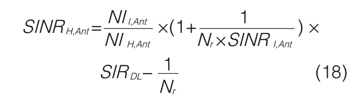
where,SINRH,Antis the received average SINRfor each antenna on the home BS,and
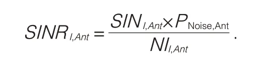
Equation(18)can be further simplified:

whereγis a derived parameter to control the interference to other cells:
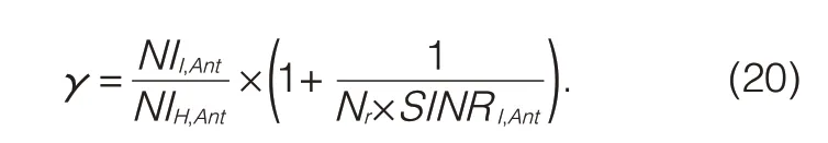
The parameter,γ,is linearly related to the ratio of virtual-cell average NI level to home-cell average NIlevel.Highγresults in high interference over thermal(IoT),and lowγresults in low IoT.
4.2 Limitation of Minimum Transmission Rate
Equation(19)provides the optimal solution for the SMSTalgorithm.The resulting target SINRon each antenna is expressed as a linear value.From(19),some MSs could have negative target SINRbecause of the very low measured downlink SIR.For these MSs,the results of(19)indicate that any power assigned to these MSs reduces overallthroughput.Because all active MSs must support a minimum transmission rate to keep them online,the minimum target SINR(to support the minimum transmission rate)should be set as the threshold.Then,(19)is modified as follows:
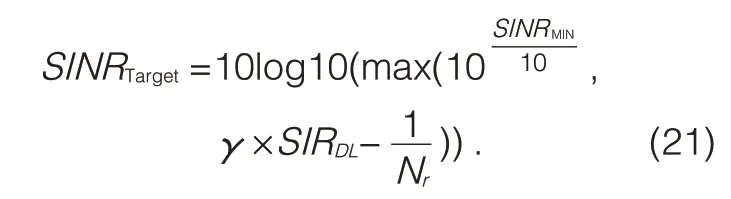
In(21),the resulting target SINRis converted to decibels so that the transmission power can be conveniently calculated.The minimum SINRthreshold is expressed in decibels and is converted into a linear value to align with the linear result of(19).Equation(21)is a core part of the IEEE 802.16m[3]uplink power-control algorithm.
Equation(21)is the SMSTalgorithm combined with minimum target SINR threshold.It expresses the suitable uplink target SINRin each receiving antenna on a home BS.If OLPC is applied,the PSD of each data subcarrier used by the MSis

where L is the average downlink path loss measured by MSbase on BS transmission power leveland received signal power level,NI is the average noise and interference level for each subcarrier at the BSantenna,the information is broadcasted from BSto MS,and Offset is the MS-specific power offset decided by the BS.
If(21)is used for conventional CLPC design,MSneeds to report the measured downlink SIRvalue SIRDLto BSperiodically,and BSthen uses(21)to calculate the target SINR.Compared with the measured SINR,the difference is compensated by CLPC commands.
Equation(21)is the solution for uplink single stream.In IEEE 802.16m[11],two options for uplink multistream power control were discussed.The power level of each stream in uplink multistreams can be kept the same as the single stream or the power level of each stream in uplink multistreams can be reduced to keep the sum of power/interference similar to the single stream.Both options improve performance in different cell sizes and in different scenarios,so there is one additional controlparameter added into(18)to support both options:
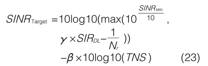
whereβis the newly added parameter and can be set by the BSas 0(disabled)or 1(enabled)for environment performance tuning.TNS is the total number of uplink multistreams.
Equation(23)is the final derivation of SMSTadopted into IEEE 802.16m[3]for data-channel power control.16 m control-channel power-control design was discussed in[14].
5 Algorithm Evaluation and Comparison
5.1 Evaluation Considerations
Before evaluating uplink power control algorithms,the following general points for system-level simulation need to be considered:
?sector-cumulated throughput and cell-edge throughput.These are the metrics of overallperformance determined by uplink power-control algorithms.
?fairness control curve.In general,the uplink power control algorithm provides a trade-off between sector-cumulated throughput and cell-edge throughput.One new-form curve is used to show the sector SEand cell-edge SE(Figs.3,4,8 and 9).
?IoTcontrol.IoTis the key metric of uplink interference in a system evaluation.Effective IoTcontrol needs to be proven for an uplink power control algorithm.
As(22)and(23)show,there are some key parameters that need to be evaluated and discussed for real implementation:
?γplays a key role in IoTand fairness.In the evaluation,the results of differentγvalues are discussed
?SINRMIN(d B)is the minimum threshold for cell-edge user SINR.
?L is the average downlink path-loss measured by the MS.This is key to deciding the transmission power level.For different product implementations,the long-term average or short-term average have cause different effects.
?The open-loop power adjustment is decided by the MS.The rate of power control may be used in product implementation.Fast(per-frame)or slow(per 50 frames)control rates are evaluated.
5.2 Results and Discussion
The evaluation scenario in[15]
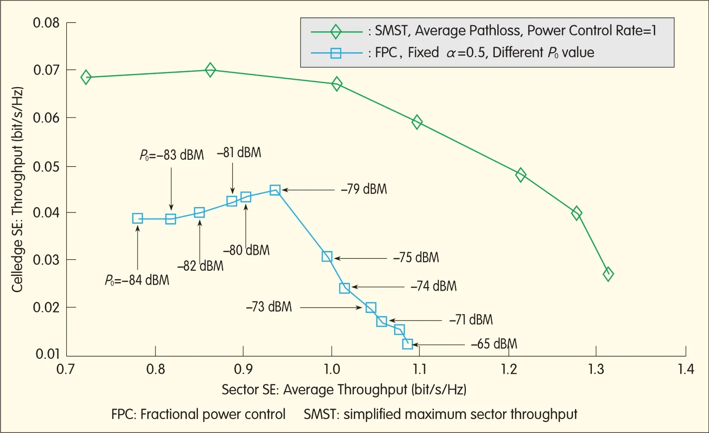
▲Figure 8.Comparison of SMSTand FPCperformance curves(with fixedα=0.8).
where SNRTargetis the cell edge target SNR,PSDnis the thermal noise PSD,and PSDMaxis the maximum transmission power PSD for assigned resource size.
Equation(26)provides the connection betweenαand P0.As a result,ifα=0,then(25)becomes

FPC degenerates to a maximum transmission power scheme.Ifα=1,then(25)becomes

FPCdegenerates to a fixed receiving-target SNRmethod.A comparison of the performances of fixed-target SNRis shown in Fig.9.In Fig.9,the optimal performance point of FPC algorithm is difficult to identify.One selected performance point for FPC(SNRTarget=6 d B,α=0.6)is used for performance comparison,its sector SEis 1.0799,and its cell-edge SEis 0.0350.If SMSTmaintains the same sector SEas FPC selected point of 1.0799,the SMSTcan provide cell-edge SEof 0.0607,which is a 73.43%gain over 0.0350 of FPC selected cell-edge SE.If SMST maintains the same cell-edge SEas FPC optimum point of 0.0350,the SMST can provide sector SEof 1.2904,which is 19.49%gain over 1.0799 of FPC selected sector SE.Also,the average gain of SMSTcompared with FPC can be as much as 46.46%.From Fig.8 and Fig.9,SMSTperforms 40%better than FPC.
6 Conclusion and Discussion
In this paper,we have proposed a noveluplink power control algorithm,SMST,for MIMO-OFDMA systems.We also performed extensive system-level simulations to compare different uplink power control algorithms,including the FPC adopted in 3GPPLTEand LTE-Advanced.Our results show that SMSTadopted in IEEE 802.16m outperforms other algorithms in terms of spectral efficiency,cell-edge performance,interference control,and tradeoff control between sector-accumulated throughput and cell-edge user throughput.The SMST performance gain over FPC can be more than 40%.
- ZTE Communications的其它文章
- ZTE Becomes Global Leader in CDMA Base Station Market w ith 33%Share
- The Internet of Things and Ubiquitous Intelligence(4)
- Mobile Backhaul Solutions
- Spatial Load Balancing in Wide-Area Wireless Networks
- Enhanced Cell-Edge Performance with Transmit Power-Shaping and Multipoint,Multiflow Techniques
- Advances in Mobile Data Communications