Modeling and Simulation for Complex Repairable System with Built-in Test Equipment
2011-03-09 11:56:58LVXuezhi呂學志YUYongli于永利ZHANGLiu張柳RENFan任帆
Defence Technology
2011年2期
LV Xue-zhi(呂學志),YU Yong-li(于永利),ZHANG Liu(張柳),REN Fan(任帆)
(1.Department of Equipment Command,Ordnance Engineering College,Shijiazhuang 050003,Hebei,China;2.Artillery Command Academy,Xuanhua 075100,Hebei,China)
Introduction
As the built-in test(BIT)is applied widely,to research its effect on systems and select BIT and test strategy becomes very important.Currently,many researchers are engaged in modeling and simulation for the complex repairable system,to evaluate the availability,mean time to failure(MTTF)and mean time to repair(MTTR)of system from the reliability and maintainability of subsystem[1-7].A lot of literatures show that,in many researches,the BIT diagnostic process is ignored,or it is added into the maintenance process,and the diagnostic time is counted into the maintenance time.Though,it can simplify the model,however,it loses the accuracy of simulation,and the effects of BIT type and test strategy on the system can not be known.Therefore,this paper puts forward a modeling and simulation approach for complex system,and discusses its diagnostic process of complex system with built-in test equipment(BITE).
In order to make the diagnosis easy and rapid,an important approach is to set special hardware and software in the system,or to test,isolate the fault and monitor the system status with some function components.Thus,the system itself can determine whether it is in normal conditions,or which components are in failure.This is BIT.Therefore,BIT can be defined as an automatic function to test and isolate fault components in system or device.The identifiable part to accomplish BIT is named as BITE.
There are many kinds of BIT.According to the start and execution modes,BIT can be divided into 3 types:1)Continuous BIT,monitoring the system status continuously and automatically,when some component is in failure,it outputs signal or indication;2)Period BIT,testing and isolating fault components in certain frequency,works automatically without special start;3)Start BIT,testing and isolating the fault only after exterior event happens,such as operator turn it on.Whenever the equipment powers on,the routine test procedure runs,this type of BIT is called as power-on BIT,it is a special sample of start BIT.
1 Modeling Methods of BITE in Complex Repairable System
1.1 Considerations in BITE Modeling
The objective of modeling and simulation of complex repairable system is to evaluate its availability,MTBF and MTTR.The influence of diagnosis process is that there may be some errors and uncertainty,and the right diagnosis can reduce unnecessary maintenance time.
Assume that the complex repairable system consists of m subsystems.Let Cjdenote the fault event of subsystem j,and Djdenote that the diagnosis result shows the subsystem j is in failure,j=1,2,3…,m.Each diagnosis is independent.There may be two kinds of errors,F+and F-.The probability of error F+is


Moreover,Xjdenotes the time for test of subsystem j,Yjdenotes the maintenance time of subsystem j when it is in failure really,Zjdenotes the maintenance time of subsystem j when it is not in failure.
1.2 Modeling Methods
The modeling and simulation tool used in this paper is SimEvents and Stateflow,and they are two modules of Simulink in Matlab.The core of BIT modeling is to simulate the process that BITE obtains the diagnosis result according to the subsystem status and triggers the corresponding maintenance.Because the continuous BIT is a special sample of period BIT with very short test period,we only introduce the modeling methods of start BIT and periodic BIT in this paper.
1)Start BIT.Its operation mechanism is that the test begins when the system faults;after the maintenance tasks corresponding to diagnosis results finish,if system has still not recovered yet,the new test and repair begin again till the system runs normally,the repaired subsystems need not to be tested and repaired.Fig.1 gives a sample model of start BIT based on Stateflow.The model has two states,“on”and“off”representing“normal”state and“failure”state respectively.The condition to start BIT is that the system faults,and it can be described as a transition“en(sys.off)”from“on”to“off”;the condition to end BIT is that the system runs normally again,and it can be described as a transition“en(sys.on)”from“off”to“on”.Function“Diagnose()”is used to simulate the uncertainty of BIT diagnosis result for the subsystem status according to error probability,as shown later in Fig.16.The array DRjand a represent diagnosis results together,DRjdenotes the maintenance action for subsystem j.DRjcan be set as 1,2 or 3,3 indicates no maintenance,2 indicates unnecessary maintenance,and 1 indicates necessary maintenance.a represents the number of subsystem necessary to be repaired.Function“IstoRep”is used to determine the maintenance action according to the value of a,as shown later in Fig.17.y represents the diagnosis time.Array djdenotes the state of subsystem j,in maintenance or in waiting,and it can be used in function“Diagnose()”to determine whether subsystem j needs to be tested.Variable s is used to count the number of repaired subsystem.If s equals to a and system have not entered into“on”state,a new cycle of test and repair begins.
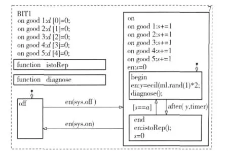
Fig.1 Start of BIT
2)Period BIT.In a relatively simple case that the system does not stop when the diagnosis results show some subsystems fault and repairing action takes place,as shown in Fig.2,the variables and functions are the same as start BIT.This period BIT detects the subsystems neither in waiting nor in maintenance state every certain time,and determine maintenance action according to the diagnosis results.
Another period BIT is that the system stop running when the diagnosis results show some subsystems fault and repairing action takes place.This period BIT detects the system every certain time,when diagnosis results show that some subsystems are in failure,the system does not operate in the subsystems’repairing until the necessary maintenance is finished.
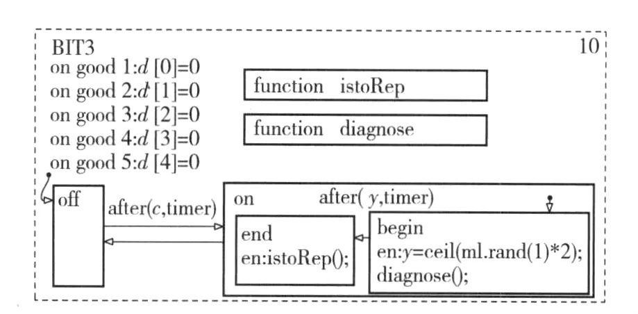
Fig.2 Periodic BIT 1

Fig.3 Periodic BIT 2
1.3 Parameter Statistic Model

The parameter statistic models are where A is the availability,MTBF the mean time between faults,MTTR the mean time to repair,MLDT the mean logistics delay time,ttthe total simulation time,tgthe uptime of system,trthe total maintenance time,m the total number of repair times,n the total number of system failure.
2 Simulation Example
A complex repairable system consists of 5 subsystems.Fig.1 gives its fault tree.Tab.1 provides the failure and repair time distribution and subsystem parameters.Tab.2 shows the diagnosis error probability.The queue strategy of maintenance is“first failure first repair”,and there is a server in the maintenance system.The maintenance policy is correct maintenance(CM),and the repaired subsystem can be as good as new one.When the system faults,its subsystems stop.
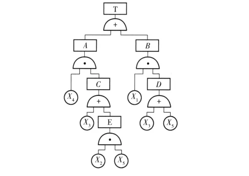
Fig.4 Fault tree of system

Tab.1 Parameters of all subsystems
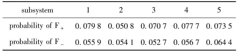
Tab.2 Diagnostic error probability
2.1 Block Diagram of System Simulation
The simulation model introduced in this paper only considers the situation that the system stops when some subsystems are in failure and repaired.Another situation is different from it slightly only and the simulation model can be modified easily.In Fig.5,the simulation block diagram can be divided into 3 parts,SimEvents at top,Stateflow and SimEvents at bottom.They are connected by 7 events,such as “fault”,“timer”,and“good1”to“good5”.
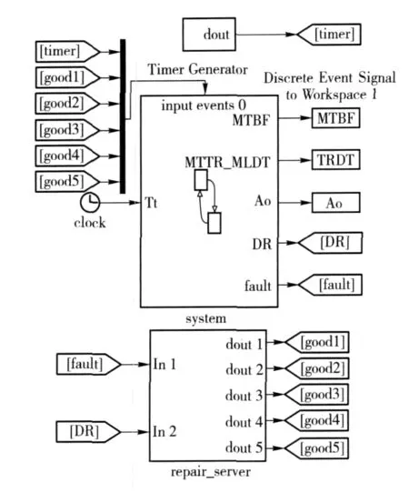
Fig.5 Block diagram of system simulation
2.2 SimEvents
Fig.6 shows the Timer Generator.It generates entity every equal time interval,and transform into events to simulate the clock advance making the Stateflow operating.

Fig.6 Timer Generator

Fig.7 Repair_Server
Repair_Server in Fig.7 describes that the subsystem experiences two actions,i.e.,queue waiting and repairing.Firstly,Stateflow sends a signal representing the subsystem failure,and it passes through Entity Generator subsystem and is transformed to entity representing failure,as shown in Fig.8.Stateflow also sends a signal representing BITE diagnosis results,and it passes through Signal Generator subsystem and is transformed to a signal describing the entity flow direction,as shown in Fig.9.Then,these entities enter into Set Servicetime subsystem,go out from different exits,and get different maintenance times according to BIT diagnosis results.If DRjequals to 3,it flows into Entity Sink to cancel;if DRjequals to 2,it represents that the maintenance is unnecessary;if DRjequals to 1,it represents that the maintenance is necessary.
Next,after each entity passes through“Path Combiner”,then enter“FIFO Queue”and queues according to the rule of“first come first serve”.Then,the entity enters“N-Server”to be repaired.Also,the entity enters“Output Switch”to be classified,and flows into different ports.Finally,the entity enters into“En-tity Sink”and sends“good”event representing the finish of maintenance task to Stateflow.
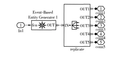
Fig.8 Entity Generator

Fig.9 Signal Generator

Fig.10 Set Servicetime

Fig.11 End Entity
2.3 Stateflow
Firstly,add Stateflow model into simulation model of Simulink and rename it as“system”;secondly,add parallel state:E1,E2,E3,E4,E5,BIT and sys,as shown in Fig.12.Thirdly,add data,event and function into“system”.From Fig.5,we can see the inputs of“system”are six events,such as“timer”and“good1”;the output is“fault”.The output data are availability Ao(),MTBF,MTTR_MLDT and DR;the local data are total repair times m,total system fault times n,simulation time Tt,total system uptime Tg,total repair time Tr.
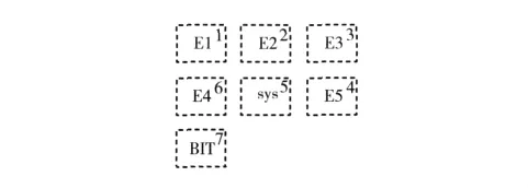
Fig.12 Stateflow
E1,E2,E3,E4 and E5 represent corresponding subsystem respectively,their block diagram structures are the same,and data and events are different slightly only,therefore,we only provide the block diagram of“E1”,as shown in Fig.13.

Fig.13 E1 chart
The main function of“sys”is to respond some events,such as“FAULT”,“GOOD”,“BitFault”,and change state,as shown in Fig.14.As long as“sys”is active,it calculates the parameters Ao,MTBF,MTTR_MLDT,according to equations(3)to(5).When event“FAULT”or“GOOD”happens,“sys”will calculate the value of“condition”by using true table,then,determine the system state according to value of“condition”and event.When“sys”enters into“on”state,the simulation clock will be recorded;when“sys”exits“on”state,the total uptime of system will be accumulated.
The true table to judge the system state is“L=Isok(A,B,C,D,E)”.According to the minimal cut set of fault tree,it can be constructed.Analyzed the fault tree,its minimal cut set is{X1,X5},{X1,X3},{X2,X4,X5}and{X3,X4}.From the definition of minimal cut set[11],we know that,as long as all of events in one of minimal cut sets happen simultaneously,the system fault,thus,they can be transformed to the true table function,as shown in Tab.3,where A,B,C,D and E are the inputs of true table,they denote the state of E1,E2,E3,E4 and E5,and their value 0 or 1 represents the subsystem uptime or downtime,respectively.L is an output of true table,it denotes the state of system,and its value 0 or 1 represents the system uptime or downtime.Decisions D1 to D4 correspond to four minimal cut sets,D5 is a default decision,and it is similar to the default branch in switch-case in C programming language.“-”can take the value of 0 or 1.For example,D1 corresponds to minimal cut set{X1,X5},it means that the system faults when E1 or E5 faults,the values of A,B,C,D and E correspond to D1 are 0,-,-,-,0 in D1;the action corresponding to D1 is 1,and the output L corresponding to D1 is 0.
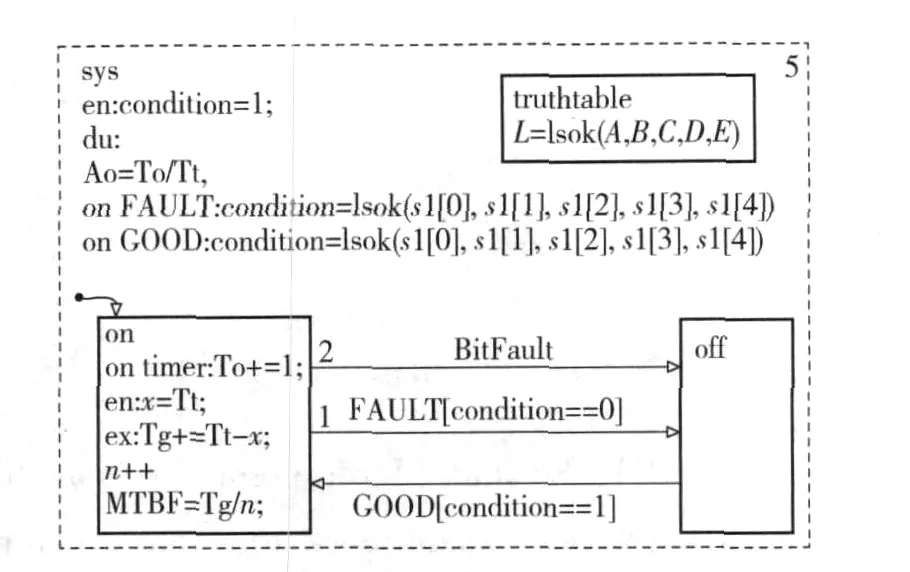
Fig.14 Sys block diagram
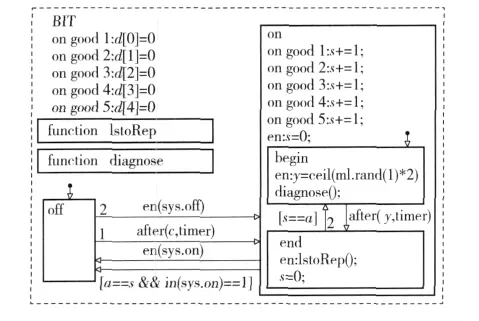
Fig.15 BIT block diagram
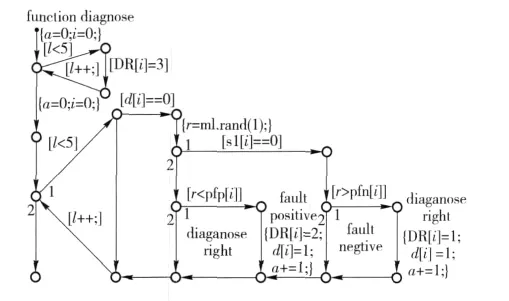
Fig.16 Diagnose function

Fig.17 IstoRep function

Tab.3 Isok true table function
2.4 Simulation Results
The effects of type of BIT,maintenance time and error probability on the system availability are simulated.Tab.4 shows the system availability of different types of BIT in the situation that the system stops when its subsystem faults.It can be seen that the system availability corresponding to start BIT is the highest,while the lowest for the continuous BIT,and the system availability of period BIT decreases with the decrease of the period.The reason is that,in the situation that the system stops when the subsystem faults,for a certain time,with the period decrease,the number of test increase,the ratio of maintenance time to total working time increase also,thus the system availability becomes lower.Tab.5 provides the system availability of different types of BIT in the situation that the system does not stop when the subsystem faults.It can be seen that the system availability corresponding to start BIT is the lowest,while the system availability of continuous BIT is highest,and the system availability of period BIT increases with the increase of its period.Tab.6 gives the availability of complex system with start BITE with different reduction of necessary maintenance time Yj.Tab.7 shows the availability of complex system with start BIT changes with different reduction of unnecessary maintenance time Zj.It can be seen that the system availability does not change obviously,because the error probability is lower,and the unnecessary maintenance is less,it can not influence the system availabi-lity significantly.Tab.8 indicates the availability of complex system with start BIT in different error probabilities.It shows that the system availability does not change significantly with the decrease of error rate.

Tab.4 Simulation results for different types of BIT in situation 1

Tab.5 Simulation results for different type of BIT in situation 2
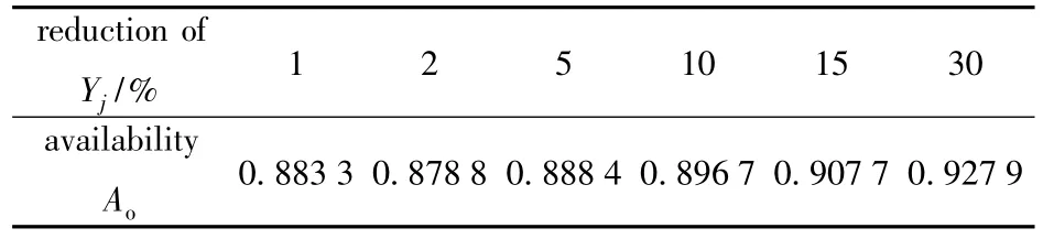
Tab.6 Simulation results for reduction of Yj

Tab.7 Simulation results for reduction of Zj

Tab.8 Simulation results for reduction of error probability
3 Conclusions
This paper analyzes the complex repairable system with BITE,puts forward a modeling and simulation approach for it,provides its specific simulation model,and the influences of diferent types of BIT,maintenance time and error probability on the system availability are simulated and evaluated by using the model.
[1]ZHANG Yu-tao,TANG Jun,ZHANG Ming-qing,et al.Research on reliability simulation process model based on Monte Carlo method[J].System Engineering and Electronics,2008,(7):1374-1377.(in Chinese)
[2]SHAO Yan-feng,XUE Hong-jun.Simulation for reliability analysis based on fault tree[J].Journal of Mechanical Strength,2008,(3):381 -385.(in Chinese)
[3]SU Chun.Simulation research on system dynamic reliability based on general stochastic Petri net[J].China Mechanical Engineering,2008,(1):1 - 5.(in Chinese)
[4]YANG Kai,Hisham Younis.A semi-analytical Monte Carlo simulation method for system’s reliability with load sharing and damage accumulation[J].Reliability Engineering and System Safety,2005,87:191-200.
[5]YANG Yu-hang,FENG Yun-cheng.Survey of reliability and availability evaluation of complex system usinng Monte Carlo techniques[J].System Engineering-theory &Practice,2003,(2):80-85.(in Chinese)
[6]YANG Yu-hang,FENG Yun-cheng.Complex repairable system reliability and maintainability simulation[J].Journal of System Simulation,2002,(8):978-986.(in Chinese)
[7]YANG Wei-min,SHENG Yi-xing.System reliability simulation[M].Beijing:Press of Beijing University of Aeronautics and Astronautics,1990.(in Chinese)
[8]LV Xue-zhi,YU Yong-li,CHEN Li-yong,et al.A modeling and simulation approach of complex repairable system based on simulink[J].Journal of Academy of Armored Force Engineering,2009,(4):15-20.(in Chinese)
[9]LV Xue-zhi,YU Yong-li,LIU Chang-jiang.A modeling and simulation approach of complex repairable system based on stateflow[J].Command Control& Simulation,2009,(6):71 -75.(in Chinese)
[10]GAN Mao-zhi,KANG Jian-she,GAO Qi.Military equipment maintenance engeering[M].Beijing:National Defence Industry Press,2005:184-186.(in Chinese)
[11]CAO Jin-hua,CHENG Kan.Introduction of reliability mathmatics[M].2nd ed.Beijing:Higher Education Press,2006:122-134.(in Chinese)
[12]ZHANG Wei.Stateflowlogistic system modeling[M].Xi’an:Xi’an Electronic Technology University Press,2007.(in Chinese)
登錄APP查看全文

- Defence Technology的其它文章
- Experimental Investigation on Combustion Performance of Solid Propellant Subjected to Erosion of Particles with Different Concentrations
- A Real-time Monitoring System for Tire Blowout or Severe Leakage
- A Support Vector Machine Based on Bayesian Criterion
- Research on Performance of U Separator in Sand and Dust Test System
- Prefix Subsection Matching Binary Algorithm in Passive RFID System
- An Orthogonal Wavelet Transform Fractionally Spaced Blind Equalization Algorithm Based on the Optimization of Genetic Algorithm