直升機旋轉逆動力學建模及姿態控制研究
2010-01-26 08:46:36趙佳申功璋
電機與控制學報 2010年8期
關鍵詞:指令
趙佳, 申功璋
(北京航空航天大學控制一體化技術國家級科技重點實驗室,北京 100191)
直升機旋轉逆動力學建模及姿態控制研究
趙佳, 申功璋
(北京航空航天大學控制一體化技術國家級科技重點實驗室,北京 100191)
為克服直升機單點逆模型的不足,提出了旋轉逆動力學建模新方法,實現了大包線下的姿態控制。該方法采用模塊化建模思想,首先通過轉動方程逆解算,將姿態角速度指令轉化為期望的縱、橫向揮舞角和尾槳偏航力矩指令等三個關鍵狀態量,然后利用主旋翼揮舞動態逆解算和尾槳槳距指令逆解算,由關鍵狀態量解算出期望的縱、橫向周期變距角和尾槳槳距角,進而建立了直升機旋轉逆動力學模型。在此基礎上,完成了姿態控制系統設計。仿真結果表明,該模型能夠在大包線范圍內較準確地反映直升機的旋轉動態逆特性,系統能夠很好地實現姿態控制目標,在各類干擾因素存在時體現出了較強的性能魯棒性。
直升機;逆動力學;建模;大包線;姿態控制
0 Introduction
A helicopter is a special kind of versatile aerocraft,which can perform different kinds ofmaneuvers.There is increasing interest in the deployment of the helicopter for both military and civilian applications.Because it belongs to an intrinsically instability,strong coupling and nonlinear system,the research on helicopter flight control system(HFCS)design has always been important and also difficult[1].
Attitude control,as the important foundation for velocity/trajectory control,is a key part of HFCS.In recent years,control schemes based on“inversemodel”have been applied successfully in helicopter attitude control field.In these schemes,the inversemodel is used to counteract the complex rotational inverse dynamics of the helicopter,and then good control effects could be gained.
At present,a single point inversionmodel(SPIM)is the inversion model,which is widely used in helicopter attitude control[2-5].SPIM is a linear model via inverse calculating of helicopter linear model on a single flight state point.From the establishing principle,SPIM can reflect the helicopter rotation inverse dynamics(HRID)correctly nearby the chosen flight state point,but can not reflect HRID throughout the full flight envelope(FFE).Therefore,there exists largemodel error when using SPIM for helicopter attitude control throughout FFE.For solving this problem,an adaptive element(AE)is adopted to compensate themodel error of SPIM.As the complexity of helicopter dynamics,themodel error of SPIM is difficult to be described accurately.Whether AE could be able to compensate themodel error completely is still a question.In this case,for achieving flight control throughout FFE,a usual solution is to increase the learning rate of AE[4],which nevertheless will increase AE’s work burden and even cause the system unstable[2].
In order to overcome the deficiency in SPIM,a novel modeling method for HRIM is proposed.By using themethod,a nonlinear helicopter rotational inverse dynamics model(RIDM)is established,and the helicopter attitude control system is developed successfully.
1 Helicopter RIDM modeling
The allocation of three-axismoments is the key for RIDM modeling.
According to helicopter dynamics,the change of longitudinal/lateral cyclic pitch angle willmake a corresponding change in longitudinal/lateral flapping angle,which lead the change of pitch/rollmoment.The change of collective pitch angle in tail rotor will also make a corresponding change in its thrust,which lead the change of yaw moment.
On the basis of above principle,a novelmodeling method for helicopter RIDM is proposed,and themain structure of themethod is shown in Fig.1.
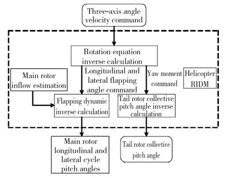
Fig.1 Main structure of helicopter RIDM
The helicopter RDIM consists of following four modules:rotation equation inverse calculation module,flapping dynamic inverse calculation module,main rotor inflow estimation module and tail rotor collective pitch angle inverse calculation module.
Based on current body attitude velocity command,the rotation equation inverse calculation module is used to calculate the expected“key states”,viz the expected longitudinal/lateral flapping angle and tail rotor yawing moment.The flapping dynamic inverse calculationmodule and themain rotor inflow estimationmodulework together to calculate the expected longitudinal/lateral cyclic pitch angle based on current longitudinal/lateral flapping angle command.The tail rotor collective pitch angle inverse calculationmodule is used to calculate the expected tail rotor collective pitch angle based on current tail rotor yawingmoment command.
In Section1.1-1.4,more details about fourmoduleswill be discussed.
1.1 Rotation equation inverse calculation module
The function of the rotation equation inverse calculation module is to calculate the key states according to the current body attitude velocities.
The helicopter rotation dynamic function is

where Ixx,Iyyand Izzdenote the moments of inertia of the helicopter about the x-,y-and z-axes;Ixzdenotes the product of the inertia about x-and z-axes;I=[Ixx0 -Ixz;0 Iyy0;- Ixz0 Izz]denotes the inertial tensor;ωx,ωyandωzdenote the body attitude velocities;L,M and N denote the three-axismoment vectors.
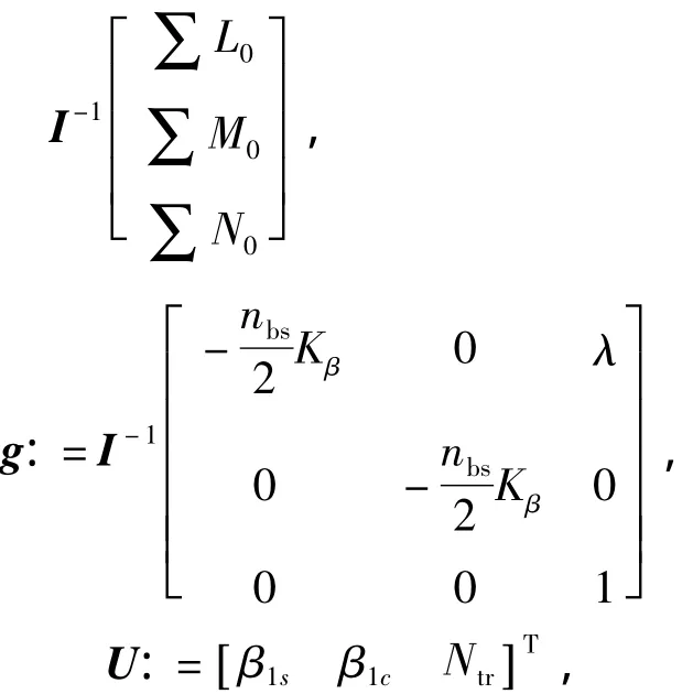
Based on helicopter dynamics,it can be seen that pitchingmoment ismainly provided by themain rotor,rollingmoment ismainly provided by themain and tail rotor,and yawing moment is mainly provided by the tail rotor.Therefore,the three-axismoment vector can be described as
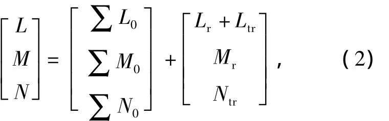
where Lr+Ltr,Mrand Ntrdenote the controllable moment vectors(subscript‘r’denotes themain rotor and‘tr’denotes the tail rotor);∑ L0,∑ M0and∑N0denote other moment vectors which can be gained via thewind tunnel experiment data and correlative calculations.
The controllable part in(2)can be expressed as[1]
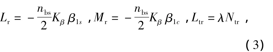
where nbsdenotes the blade number of themain rotor;Kβis themain rotor stiffness;β1cand β1sare the longitudinal and lateral flapping angles respectively;λis the proportional coefficient.
Using(1)-(3),we can obtain
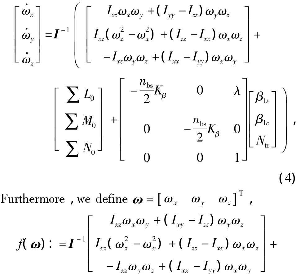
where U denotes the“key states”vector.
The helicopter rotation control problem can be described as
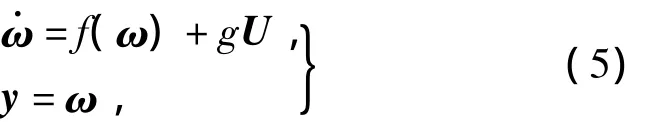
where“key states”vector U is also the pseudo input of(5).
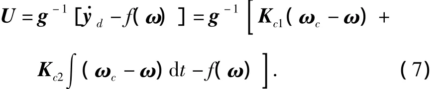
The expected dynamic response of attitude velocity vector can be described as
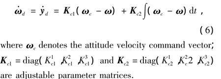
U can be obtained by means of typical dynamic inversion method
Equation(7)is the mathematical model of rotation equation inverse calculation.
1.2 Flapping dynam ic inverse calculation module
The function of the flapping dynamic inverse calculation module is to provide the expected longitudinal/lateral cyclic pitch angle based on current longitudinal/lateral flapping angle command.
Helicoptermain rotor flapping dynamic equation is[1]

where βM=[β0β1cβ1s]T,and β0,β1cand β1sdenote themain rotor coning,longitudinal and lateral flapping angles;θ =[θ0θ1swθ1cw]T,and θ0,θ1swand θ1cwdenote collective pitch angle,longitudinal cyclic pitch angle and lateral cyclic pitch angle;θtwis themain rotor blade linear twist;λis themain rotor inflow infor-mation vector;ω0is the attitude velocity information vector;Aβθ,Aβθtw,Aβλand Aβωare time-variable parameter matrices which are decided by current advanced radio.
The second,third and fourth items on the right side of(8)are far smaller than the first item,therefore,Equation(8)can be expressed as
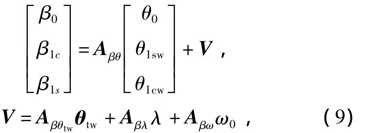
For obtaining the expected cyclic pitch angles,Equation(9)ismodified as the following form
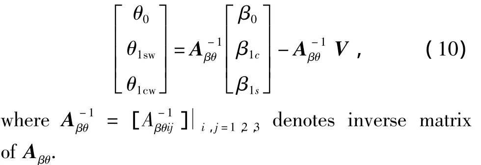
As the collective pitch angle can be considered as the slow-varying state,Equation(10)can be described as
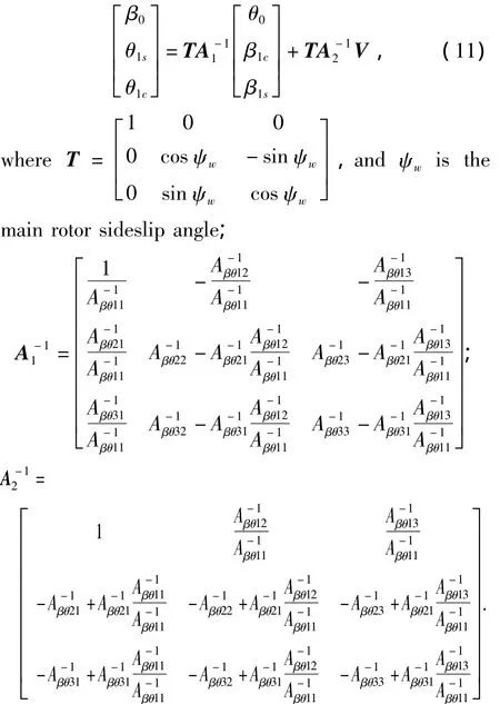
Equation(11)is themathematicalmodel for flapping dynamic inverse calculation.The main rotor inflow utilized in(11)is provided by main rotor inflow estimation module discussed in the following section.
1.3 Main rotor inflow estimation module
The function of the main rotor inflow estimation module is to provide the flapping dynamic inverse calculation module with the current estimating value of main rotor inflow.
For simplifying the calculating process,Newton’s iterative scheme based on momentum theory is used to achieve the inflow estimation[1].This scheme can be described as following equations:
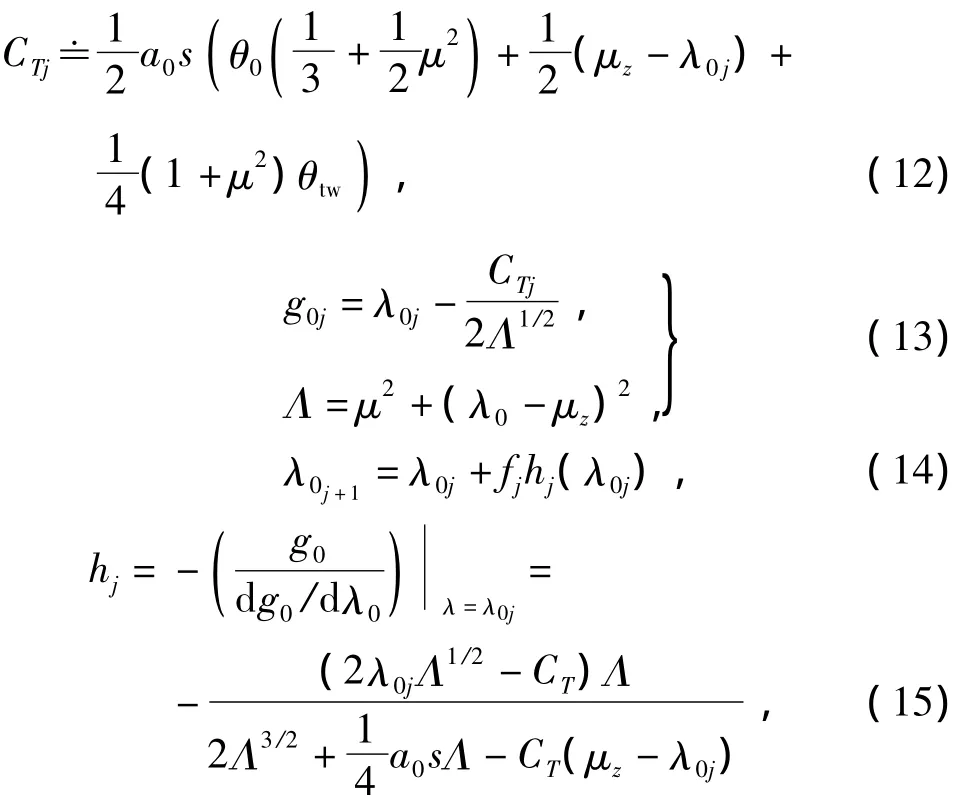
whereλ0is the currentmain rotor inflow value;CTis themain rotor thrust coefficient;a0is the main rotor lift curve slope;μis the advanced radio;μzis the uniform vertical velocity;s is the main rotor solidity;fjdenotes the convergence rate coefficientwith the value 0.6;subscript j denotes the current value and j+1 denotes the estimating value in next time.
1.4 Tail rotor collective pitch angle inverse calculation module
The function of the tail rotor collective pitch angle inverse calculation module is to calculate the collective pitch angle of the tail rotor based on current expected yaw moment.
The expected thrust of the tail rotor can be obtained based on current expected yaw moment
where ltrdenotes the distance of tail rotor hub aft of fuselage reference point;xcgdenotes the centre of gravity location forward of fuselage reference point.
Moreover,the expected thrust coefficient is gained
whereρis air density;Ωtris tail rotor speed;Rtris the tail rotor radius;Kblkdenotes the block coefficient cased by fin and tail plane.On the other hand,the thrust coefficient can be described as the following form usingmomentum theory

whereωtris the tail rotor induced velocity;μtris the uniform advanced velocity at tail rotor hub centre;μZtris the uniform vertical velocity at tail rotor hub centre.By iterative calculating(18),the expected induced velocity can be obtained.
The inverse calculation for tail rotor collective pitch angle is achieved based on the modified Bailey model[6].
The tail rotor induced velocity can be described as
where t31,t32and t33denote the Bailey coefficients;stris the tail rotor solidity;θ0Tis the tail rotor collective pitch angle;θtwpis the tail rotor blade linear twist;G=a0trstr/2,and a0trdenotes the tail rotor lift curve slope.The Bailey coefficients can be calculated as[6]
where Btrdenotes the tail rotor blade tip losing coefficient.
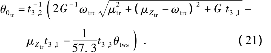
Using(19),the tail rotor collective pitch angle can be obtained
2 Attitude control scheme based on RIDM
The helicopter attitude control system has been developed using the proposed RIDM.Fig.2 shows the overall structure of the system.
As shown in Fig.2,by using“Euler angle- >angle velocity inverse calculation module”,the expected angle velocity will be calculated based on current attitude command.And then,by using RIDM,the expected longitudinal/lateral cyclic pitch angle and tail rotor collective pitch angle can be obtained based on current angle velocity commands.The attitude inverse control for the helicopter is achieved.
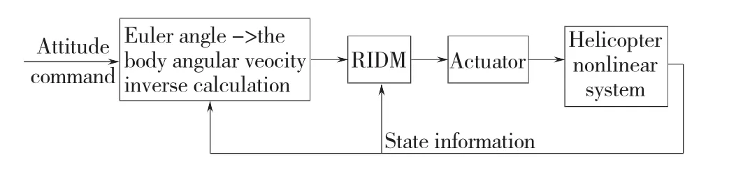
Fig.2 Structure of helicopter attitude control system
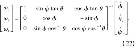
Themathematicalmodel of“Euler angle->angle velocity inverse calculationmodule”can be described as
3 Simulation results and analysis
For checking the effectiveness of the proposed RIDM model,the attitude control system has been developed based on the structure shown in Fig.2 by using a 6-DOF nonlinear mathematic model of the helicopter[7],and series of experiments have also been finished.The adjustable parameter matrices are Kc1=diag(5,3.5,4)and Kc2=diag(0.6,0.4,0.35)
In 3.1,the accuracy of RIDM on different flight states is shown.In 3.2 -3.4,the control performances of the system when existing kinds of disturbances are indicated.
3.1 Test for the accuracy of RIDM on different flight states
In the test for the accuracy of RIDM on different flight states,whether the proposed model can reflect HRID correctly on different flight states is checked.Fig.3 and Fig.4 display the three-axisattitude responseswhen tracking square signal on four different typical flight states,viz hovering,5m/s,30m/s and 50m/s forward flight.The results indicate that the system can track three-axis attitude command well on different flight states,whichmatch the ACAH demand defined in ADS-33 quite well.The coupling among three attitude responses isweak.The results indicate that the RDIM proposed in this paper can reflect HRID well throughout FFE.
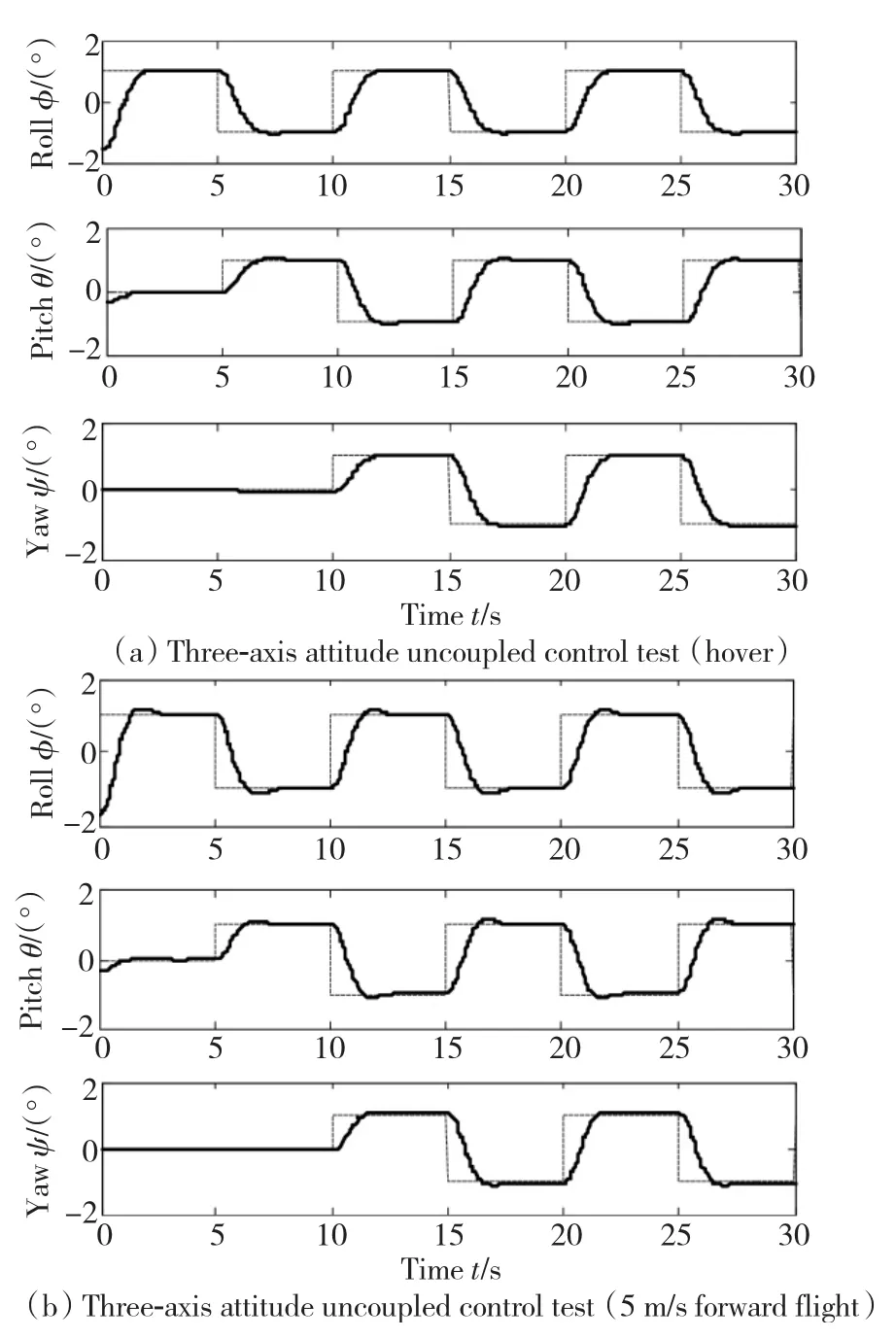
Fig.3 Three-axis attitude responses(dash line:command;solid line:response)
Among above experiments,the simulation time is 30 s and the sample time is 0.01 s.Results show the actual running time of the system is less than 20 s,which indicates good real time performance of the proposed method.
3.2 Test for side w ind disturbance
Sidewind is considered as themain disturbance to the helicopter flight system and will therefore be simulated in thewindmodule.A side wind results in a side force due to fuselage drag,a roll moment due to the main rotor dynamics and a yaw moment due to the tail rotor dynamics.
Themathematicalmodel of the wind model[8]is

The force/moment cased by side wind can be modeled as described in reference[8].
Fig.5 presents the three-axis attitude responses on hover and 50m/s forward flight statewhen existing side wind disturbance.The results indicate that the threeaxis attitude responses are all affected by the side wind,the effects on pitch angle response aremuch smaller than those on the other two responses,and after all,the system is able to achieve attitude command tracking.Thismeans that RIDM proposed in this paper has strong performance robustness when existing side wind disturbance.
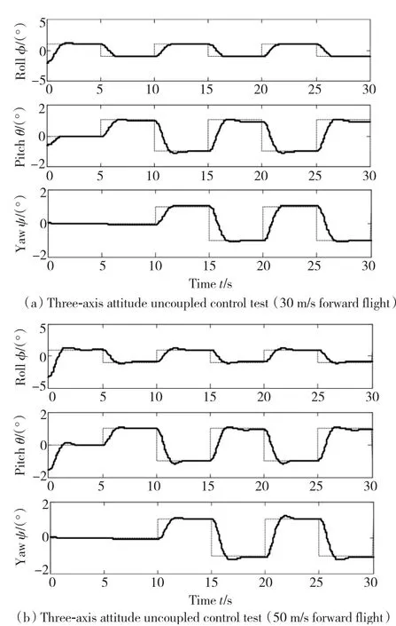
Fig.4 Three-axis attitude responses(dash line:comm and;solid line:response)
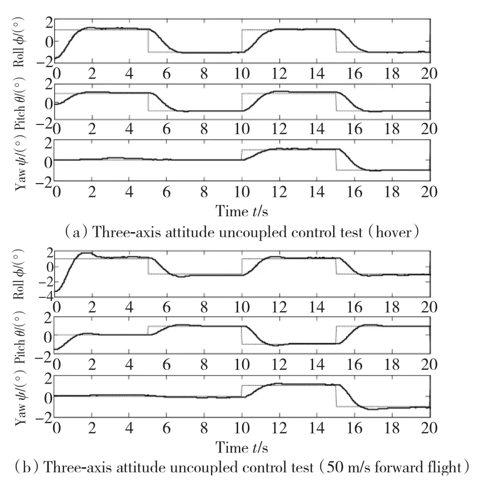
Fig.5 Three-axis attitude responses w ith side w ind disturbance(dash line:command;solid line:response)
3.3 Test for white noise disturbance
In the test for white noise disturbance,white noise disturbance with 5%intensity is added in pitch angle output channel to check the anti-interference capability of RIDM.The responses on different states are shown in Fig.6.The responses on hover and 30 m/s forward flight state are all affected by the output noise,and the effect on the former is stronger than that on the latter.The system is still able to achieve attitude trackingwell.
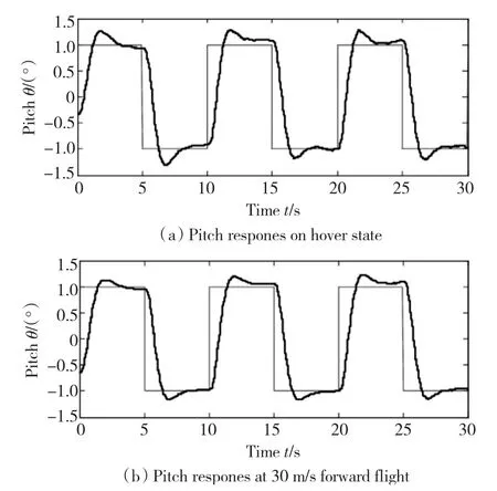
Fig.6 Pitch responsesw ith white noise(dash line:command;solid line:response)
3.4 Test for main rotor inflow estimating error
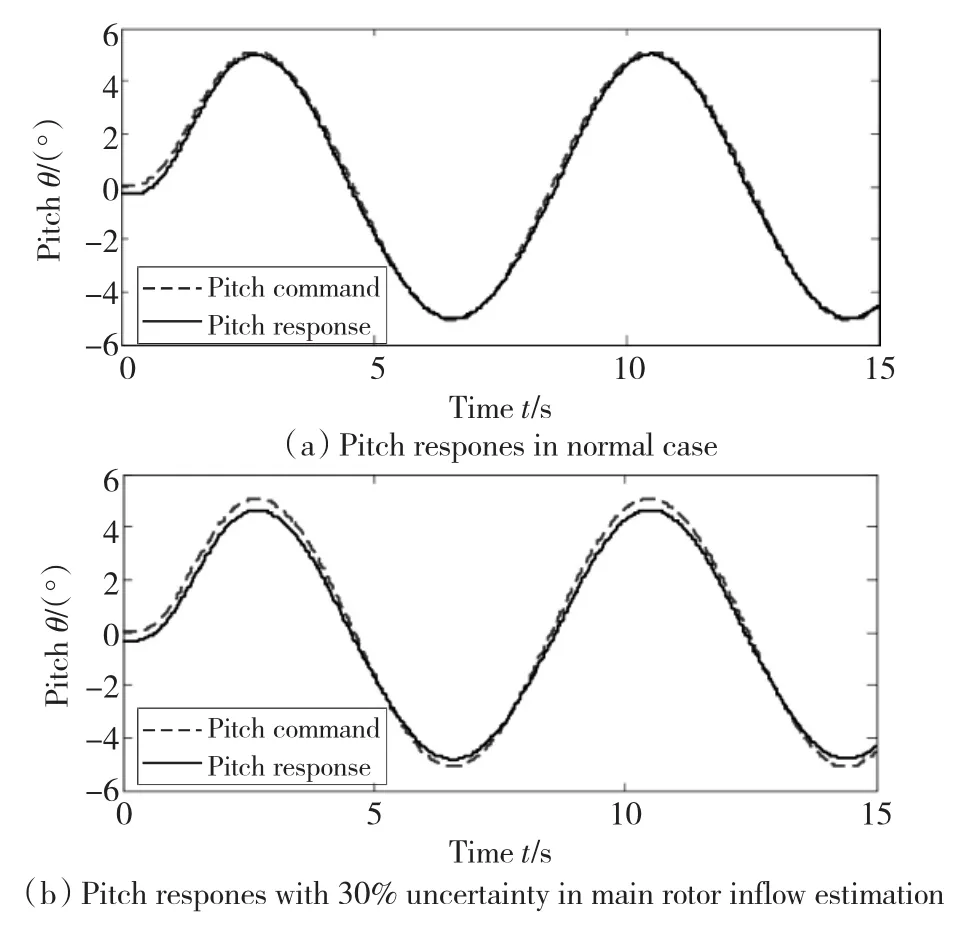
Fig.7 Pitch responsesw ith/w ithout inflow estimating uncertainty
In the proposed RIDM,a simple iterative scheme is used for main rotor inflow estimation.In fact,it is difficult to estimate inflow accurately.Fortunately,the effect of inflow in(8)is far weaker than that of pitch angles;therefore,the error in inflow estimation has small effect on the whole control system.For checking the conclusion,a 30% uncertainty is added in the main rotor inflow estimationmodule in the test formain rotor inflow estimating error.The pitch angle responses on hover statewith/without30%estimating uncertainty are shown in Fig.7.The results show that the effecton pitch angle response is weak,which means RIDM has strong robustness against inflow estimating error.
4 Conclusions
The helicopter RIDM was established by using a novel modeling method,and the helicopter attitude control system was also developed successfully based on it.Simulation results show the helicopter RIDM can reflect HRID correctly throughout FFE without AE’s compensation,which overcomes the deficiency in traditional SPIM.The system can achieve good attitude control and also has strong robustness performance when existing kinds of disturbances.
[1] PADFIELDGD.Helicopter Flight Dynamics:TheTheoryandApplicationofFlyingQualitiesandSimulationModeling[M].UK:AIAA and Black Well Science Ltd,1996:93-141.
[2] WANG Hui,XU Jinfa,Gao Zheng.Design of attitude control system based on neural network to unmanned helicopter[J].ACTA AeronauticaETAstronauticaSINICA,2005,26(6):670-674.
[3] NAKWAN K,ANTHONY JC.Adaptive output feedback for altitude control of an unmanned helicopter using rotor RPM[C]//AIAAGuidance,Navigation,andControlConferenceandExhibit.Rhode Island:AIAA Press,2004:1 -17.
[4] HUANG Weimin.HelicopterNeuralNetworkControlandImplementationofHandlingQualityRequirements[D].Nanjing:Nanjing University of Aeronautics and Astronautics,2002.
[5] ZHAO Jia,CHEN Shenggong,SHEN Gongzhang.Novel control scheme for helicopter flight:Fuzzy immune adaptive model inversion control[C]//ProceedingsofIFACWorldCongress2008.Korea:IFAC Press,2008:15046 -15051.
[6] YU Zhi.ResearchonHelicopterFlightDynamicModelingandRobust FlightControlLawDesign[D].Beijing:Beihang University,2008.
[7] YANG Chao.HelicopterFlightDynamicAffineNonlinearSystem ModelingandEstimating[D].Beijing:Beihang University,1995.
[8] NIELSEN A.HelicopterDynamicsandRobustControl[D].New York:State University of New York,2005.
Helicopter rotation inverse dynam icsmodeling and attitude control
ZHAO Jia,SHEN Gong-zhang
(National Key Laboratory of Control Integration Technology,Beihang University,Beijing 100191,China)
A novelmodelingmethod of helicopter rotation inverse dynamicswas proposed for overcoming deficiency in the tradition single point inversionmodel,and the attitude control throughout full flightenvelopewas implemented.In themethod,the attitude velocity command was transformed into three expected key states(viz longitudinal/lateral flapping angle and tail rotor yaw moment)bymeans of rotational equation inverse calculation,and from the key states,the expected longitudinal/lateral cyclic pitch angle and tail rotor collective pitch anglewere obtained by usingmain rotor flapping dynamic inverse calculation and tail rotor collective pitch angle inverse calculation.Furthermore,the helicopter attitude control system was developed based on themodel.Simulation results show the proposed modellingmethod can reflect the helicopter inverse dynamics correctly throughout full flightenvelope;the system can achieve attitude controlwellwithout compensation element and has strong robustness performance when existing kinds of disturbances.
helicopter;inverse dynamics;modeling;full flight envelope;attitude control
TP 273.2
A
1007-449X(2010)08-0031-07
2009-12-21
國家自然科學基金資助項目(60774061);高等學校博士點基金資助項目(20060006010)
趙 佳(1981—),男,博士研究生,研究方向為直升機飛行控制、綜合飛行火力控制;
申功璋(1945—),男,教授,博士生導師,研究方向為綜合飛行控制、大系統控制。
(編輯:張 靜)
猜你喜歡
科普童話·神秘大偵探(2023年1期)2023-05-30 12:48:10
測控技術(2018年5期)2018-12-09 09:04:26
電子測試(2018年18期)2018-11-14 02:30:34
電信科學(2016年10期)2016-11-23 05:11:56
時代農機(2015年3期)2015-11-14 01:14:29
科技傳播(2015年20期)2015-03-25 08:20:30
信息安全研究(2015年3期)2015-02-28 20:18:12
西安航空學院學報(2014年5期)2014-07-13 01:27:52
家電科技(2014年5期)2014-04-16 03:11:28
汽車零部件(2014年2期)2014-03-11 17:46:27

- 電機與控制學報的其它文章
- 非線性系統的多項式近似表示及電力系統應用(Ⅰ)——理論篇